EP0345080A2 - Ventilateur moulé à plusieurs parties pour générateurs - Google Patents
Ventilateur moulé à plusieurs parties pour générateurs Download PDFInfo
- Publication number
- EP0345080A2 EP0345080A2 EP89305581A EP89305581A EP0345080A2 EP 0345080 A2 EP0345080 A2 EP 0345080A2 EP 89305581 A EP89305581 A EP 89305581A EP 89305581 A EP89305581 A EP 89305581A EP 0345080 A2 EP0345080 A2 EP 0345080A2
- Authority
- EP
- European Patent Office
- Prior art keywords
- fan
- base member
- interlocking
- segment
- segments
- Prior art date
- Legal status (The legal status is an assumption and is not a legal conclusion. Google has not performed a legal analysis and makes no representation as to the accuracy of the status listed.)
- Withdrawn
Links
Images
Classifications
-
- H—ELECTRICITY
- H02—GENERATION; CONVERSION OR DISTRIBUTION OF ELECTRIC POWER
- H02K—DYNAMO-ELECTRIC MACHINES
- H02K9/00—Arrangements for cooling or ventilating
- H02K9/02—Arrangements for cooling or ventilating by ambient air flowing through the machine
- H02K9/04—Arrangements for cooling or ventilating by ambient air flowing through the machine having means for generating a flow of cooling medium
- H02K9/06—Arrangements for cooling or ventilating by ambient air flowing through the machine having means for generating a flow of cooling medium with fans or impellers driven by the machine shaft
-
- F—MECHANICAL ENGINEERING; LIGHTING; HEATING; WEAPONS; BLASTING
- F04—POSITIVE - DISPLACEMENT MACHINES FOR LIQUIDS; PUMPS FOR LIQUIDS OR ELASTIC FLUIDS
- F04D—NON-POSITIVE-DISPLACEMENT PUMPS
- F04D29/00—Details, component parts, or accessories
- F04D29/26—Rotors specially for elastic fluids
- F04D29/28—Rotors specially for elastic fluids for centrifugal or helico-centrifugal pumps for radial-flow or helico-centrifugal pumps
- F04D29/281—Rotors specially for elastic fluids for centrifugal or helico-centrifugal pumps for radial-flow or helico-centrifugal pumps for fans or blowers
Definitions
- a typical heavy-duty electrical generator design for example one for use on an industrial engine as the prime mover for construction equipment or the like, generally includes a significant amount of iron and copper in the core and windings thereof. This concentration of material generates a significant amount of heat in operation and requires cooling to perform efficiently.
- a steel or aluminium fabricated, cast gray iron or aluminium cast annular exhaust fan is secured to the coupling between the engine flywheel and the generator drive shaft. This fan includes a plurality of paddle blades which push air through the generator windings and core to cool them as the flywheel and drive shaft rotate. Because of the significant forces created in the engine, a flexible connection of some sort is generally used to minimize the transmission of vibration and other such disruptive forces between it and the generator.
- the present invention provides in one embodiment a rotating dynamo electric machine having a drive train comprising a driven member secured to a driving member of said machine, the improvement comprising a plastic multi-part annular fan attached to the drive train and adapted to cool the machine as the drive train rotates.
- the fan comprises a plurality of segments each comprising a generally arcuate base member with one or more fan blades extending therefrom, and an interlock means including an interlock member at each end of the base member, said interlock members having means to overlap as adjacent fan segments are attached to one another.
- the arcuate base member extends over an arc of 90 and is plastic molded with two metallic sleeve inserts for mounting of the segment to the flywheel of the drive train.
- At either end of each segment is an interlocking structure which takes a different form in each of two embodiments.
- one end is a flange-like member with a hole formed therein and the other end is a platform member with a metallic sleeve molded therein such that a flange of one segment overlies a platform of an adjacent segment with the hole in the flange fitting over the upstanding portion of the metallic sleeve, the sleeve extending substantially the entire height of the base of the segment.
- a bolt is then passed through the hole in the flange and the metallic sleeve and has a threaded end which secures the flange, the platform, and where present the flexible coupling to the flywheel.
- a bolt is used to secure each fan segment at its point of juncture to the fly-wheel. This is important as the fans are generally tested at greater than their normal operating speed for several hours at maximum operating temperature to ensure their long life in the field. This interlocking structure has been found sufficient to pass this test.
- the interlocking structure is modified by utilizing a half-height base member at one end of the segment, and a half-height base member at the other end of the segment, the half-height base members being arranged so that they overlie one another, with the same metal cylindrical sleeve being molded into one of the half-height base members and the other having a hole therein so that it may be fitted over the sleeve and mounted by a single bolt to the flywheel as with the first embodiment.
- This second embodiment is thought to be an improvement over the first embodiment in that it eliminates the somewhat thinner flange portion of the interlock and instead utilizes half-height base members which are thought to be less susceptible to cracking during operation.
- the invention therefore also provides a fan assembly for attachment to the drive member of a generator, which fan assembly comprises a plurality of segments adapted to be attached to one another to form an annular fan, which segments comprise a generally arcuate base member carrying one or more fab blades extending therefrom, each segment being provided with an interlocking member at each end thereof, one of said interlocking members comprising a cylindrical sleeve and the other of said interlocking members having means defining an aperture for receiving the cylindrical sleeve of an adjacent fan segment when the fan segments are assembled together.
- the interlocking structure at each end of each segment may be utilized to pre-assemble the fan prior to its assembly to the generator.
- the metal cylindrical sleeves which are molded into the segments may be used to match and line up the segments and facilitate its pre-assembly prior to installation.
- the fan segments may be individually mounted one at a time to the generator. This approach has the advantage of permitting the installer to handle smaller pieces of the fan and support it as it is being installed. Although it is generally believed that pre-assembly of the segments into a fan results in easier installation in the majority of designs, either approach may be utilized depending upon the particular design and preference of the installer.
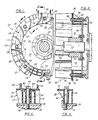
- Figure 1 is a partial front view of an assembled multi-piece fan of the present invention as mounted to a flywheel;
- Figure 2 is a cross-sectional view taken along the plane of line 2-2 in Figure 1 detailing the mounting of the fan to the flywheel;
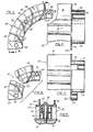
- Figure 3 is a cross-sectional view taken along the plane of line 3-3 in Figure 1 detailing the construction of the interlocking members;
- Figure 4 is a cross-sectional view taken along the plane of line 4-4 in Figure 1 detailing the mounting of the fan segment to the flywheel;
- Figure 5 is a top view of a single segment of the multi-piece-fan;
- Figure 6 is a partial staggered cross-sectional view taken along the plane of line 6-6 in Figure 5 further detailing the interlocking portions of the first embodiment;
- Figure 7 is a partial staggered cross-sectional view similar to Figure 6 except detailing the interlocking members of the second embodiment;
- Figure 8 is a segmented top view of the two ends of the segment comprising the second embodiment;
- Figure 9 is
- the multi-piece fan 20 of the present invention is comprised of four segments 22, each segment 22 being a one-piece molded member having an arcuate base member 24 and a plurality of upstanding fan blades 26.
- the fan blades 26 have a generally arcuate shape themselves to scoop the air and propel it through the windings of the generator, as is known in the art.
- Each segment 22 has a number of ribs 28 which extend between the base member 24 and the base platform 30 which supports the fan blades 26.
- the engine flywheel 32 is coupled to the generator drive shaft 34 and drive hub 36 by a generally annularly shaped flex plate 38. This helps reduce the transmission of vibrational forces between the flywheel 32 and shaft 34, as known in the art.
- the fan segments 22 are secured to the flywheel 32 by a plurality of bolts 40, each of which extends through a generally cylindrical metal sleeve 42 molded into the base member 24 of the fan segments 22. Each fan segment 22 has two of the cylindrical metal sleeves 42.
- each fan segment 22 of the first embodiment has a flange 44 with a hole 46 therein, hole 46 being sized to slip over the top and surround the metallic sleeve 42 which is moulded into a platform member 48 in an adjacent fan segment 22.
- bolt 40 is slipped through sleeve 42 it not only secures adjacent fan segments 22 together, but also mounts them to flywheel 32 and flex plate 38.
- This interlocking structure greatly increases the strength with which the fan segments 22 are held in place, not only with respect to each other but also with respect to the overall assembly. This is important in maintaining the structural integrity of the fan 20 as vibrational forces and torsional forces are introduced therein during operation of the engine and generator.
- the fan segment 22 may have a different interlocking structure to secure the segments 22 together and to the flywheel 32.
- a half-height base member 50 at one end of fan segment 22 has an integrally moulded cylindrical metal sleeve 52 which extends substantially the same height as the base portion 24.
- another half-height interlocking member 54 with a hole 56 therethrough is assembled by inserting cylindrical sleeve 52 through the hole 56 in interlocking member 54, and then inserting threaded bolt 40 therethrough.
- This second embodiment is believed to provide somewhat more reliable mounting of the fan segments 22 in that flange 44 of the first embodiment is eliminated and instead a half-height interlocking member 54 is utilized which is thought to be less susceptible to cracking during use.
- the fan segments 22 may be pre-assembled prior to their being secured to the flywheel 32 by bolts 40.
- the cylindrical metal sleeve 42 of each fan segment may be interfitted with the hole 46 in flange 44 to pre-assemble the four fan segments 22 comprising the multi-piece fan 20.
- cylindrical metal sleeve 52 may be interfitted with the hole 56 in half-height interlocking member 54 to pre-assemble the four fan segments 22 into a fan 20.
- pre-assembly careful alignment and interfitting of the various fan segments 22 together may be achieved without the problem of slight misalignments caused by individually securing the fan segements 22 with bolts 40.
- an installer may have a particular preference with regard to particular designs such that either assembling the fan segments 22 individually or as a pre-assembled fan 20 may be used, as desired.
Landscapes
- Engineering & Computer Science (AREA)
- Mechanical Engineering (AREA)
- General Engineering & Computer Science (AREA)
- Power Engineering (AREA)
- Structures Of Non-Positive Displacement Pumps (AREA)
- Motor Or Generator Cooling System (AREA)
Applications Claiming Priority (2)
| Application Number | Priority Date | Filing Date | Title |
|---|---|---|---|
| US07/201,886 US4879483A (en) | 1988-06-03 | 1988-06-03 | Molded multi-part generator fan |
| US201886 | 1988-06-03 |
Publications (2)
| Publication Number | Publication Date |
|---|---|
| EP0345080A2 true EP0345080A2 (fr) | 1989-12-06 |
| EP0345080A3 EP0345080A3 (fr) | 1990-06-13 |
Family
ID=22747684
Family Applications (1)
| Application Number | Title | Priority Date | Filing Date |
|---|---|---|---|
| EP89305581A Withdrawn EP0345080A3 (fr) | 1988-06-03 | 1989-06-02 | Ventilateur moulé à plusieurs parties pour générateurs |
Country Status (3)
| Country | Link |
|---|---|
| US (1) | US4879483A (fr) |
| EP (1) | EP0345080A3 (fr) |
| JP (1) | JPH0226249A (fr) |
Cited By (1)
| Publication number | Priority date | Publication date | Assignee | Title |
|---|---|---|---|---|
| WO2006059874A1 (fr) * | 2004-12-03 | 2006-06-08 | Daewoo Electronics Corporation | Systeme de rafraichissement d’un rotor externe |
Families Citing this family (17)
| Publication number | Priority date | Publication date | Assignee | Title |
|---|---|---|---|---|
| US5206743A (en) * | 1990-12-28 | 1993-04-27 | All The Fax Business Systems, Inc. | Facsimile routing methodology |
| US5144175A (en) * | 1991-05-15 | 1992-09-01 | Siemens Energy & Automation, Inc. | Cooling fan for electric motors |
| JP2828587B2 (ja) * | 1993-12-28 | 1998-11-25 | 三菱電機株式会社 | 車両用交流発電機の冷却用ファン |
| US5454690A (en) * | 1994-01-13 | 1995-10-03 | Shop Vac Corporation | Air flow housing |
| US6150743A (en) * | 1997-04-24 | 2000-11-21 | Electric Boat Corporation | Composite motor end housing with a metallic sleeve bearing support |
| JP3449330B2 (ja) | 2000-01-31 | 2003-09-22 | 株式会社日立製作所 | 車両用交流発電機 |
| JP2002238217A (ja) * | 2001-02-08 | 2002-08-23 | Sawafuji Electric Co Ltd | 発動発電機のファン構造 |
| MXPA03008382A (es) * | 2001-03-16 | 2004-11-12 | Altech Generating Systems Llc | Alternador y metodo de fabricacion. |
| DE10344634A1 (de) * | 2003-09-25 | 2005-05-04 | Bosch Gmbh Robert | Elektrische Maschine |
| US7381029B2 (en) * | 2004-09-30 | 2008-06-03 | General Electric Company | Multi-piece wind turbine rotor blades and wind turbines incorporating same |
| JP5327742B2 (ja) * | 2005-09-27 | 2013-10-30 | ウモエ マンダル エーエス | 遠心力ファン |
| CA2766456A1 (fr) * | 2009-07-08 | 2011-01-13 | Mitsubishi Electric Corporation | Moteur electrique pour vehicule |
| CN102971945A (zh) * | 2010-08-04 | 2013-03-13 | 三菱电机株式会社 | 旋转电机 |
| AU2013263811B2 (en) * | 2012-12-03 | 2018-03-15 | International Mowers Pty Ltd | Motorised Portable Blower Apparatus |
| ITCO20130067A1 (it) * | 2013-12-17 | 2015-06-18 | Nuovo Pignone Srl | Girante con elementi di protezione e compressore centrifugo |
| JP6877317B2 (ja) | 2017-11-10 | 2021-05-26 | 三菱電機株式会社 | ウエハ容器 |
| FR3074298B1 (fr) * | 2017-11-30 | 2020-02-07 | Airbus Operations | Ensemble comprenant un profil aerodynamique et un systeme pour la determination de caracteristiques d'un ecoulement d'air incident sur un bord d'attaque du profil aerodynamique |
Family Cites Families (6)
| Publication number | Priority date | Publication date | Assignee | Title |
|---|---|---|---|---|
| US3608172A (en) * | 1968-02-05 | 1971-09-28 | Nohab Ab | Method and device for the manufacture of francis turbine runners |
| US3521973A (en) * | 1968-08-16 | 1970-07-28 | Anpol Research Corp | Fan construction |
| DE2049679A1 (de) * | 1970-10-09 | 1972-04-13 | Bosch Gmbh Robert | Lüfter für eine elektrische Maschine |
| DE2526532A1 (de) * | 1975-06-13 | 1976-12-23 | Vyzk Vyvojovy Ustav Elektric | Rotierende elektrische maschine mit radialluefter |
| CA1155712A (fr) * | 1979-10-29 | 1983-10-25 | Rockwell International Corporation | Rotor centrifuge composite pour pompes a bouillie |
| US4588915A (en) * | 1984-12-14 | 1986-05-13 | General Motors Corporation | Alternating current generator rotor |
-
1988
- 1988-06-03 US US07/201,886 patent/US4879483A/en not_active Expired - Fee Related
-
1989
- 1989-06-02 EP EP89305581A patent/EP0345080A3/fr not_active Withdrawn
- 1989-06-03 JP JP1140266A patent/JPH0226249A/ja active Pending
Cited By (3)
| Publication number | Priority date | Publication date | Assignee | Title |
|---|---|---|---|---|
| WO2006059874A1 (fr) * | 2004-12-03 | 2006-06-08 | Daewoo Electronics Corporation | Systeme de rafraichissement d’un rotor externe |
| US7385322B2 (en) | 2004-12-03 | 2008-06-10 | Daewoo Electronics Corporation | Rotor for use in an outer rotor type motor of a drum type washing machine |
| CN101069335B (zh) * | 2004-12-03 | 2012-07-18 | 株式会社东西电子 | 用在滚筒式洗衣机外转子式电机中的转子 |
Also Published As
| Publication number | Publication date |
|---|---|
| US4879483A (en) | 1989-11-07 |
| EP0345080A3 (fr) | 1990-06-13 |
| JPH0226249A (ja) | 1990-01-29 |
Similar Documents
| Publication | Publication Date | Title |
|---|---|---|
| US4879483A (en) | Molded multi-part generator fan | |
| US6177750B1 (en) | Rotating assembly construction for high speed induction motor | |
| US7919898B2 (en) | Rotor core assembly for electric motor | |
| US4993682A (en) | Vibration absorbing mounting mechanism for an automotive air conditioning compressor | |
| US5306123A (en) | Noise isolating rotor for air handler motor | |
| US6094799A (en) | Method of making double diaphragm compound shaft | |
| EP0388147A1 (fr) | Turbo-compresseur combiné avec une machine rotative | |
| US11466733B2 (en) | Coupling for power generation system | |
| US4980592A (en) | Flywheel magnet rotor assembly | |
| US5184705A (en) | Electromagnetic clutch | |
| KR101020660B1 (ko) | 가요성 디스크, 그러한 가요성 디스크가 제공된 가요성커플링, 그러한 가요성 커플링이 제공된 장착 플랜지, 및그러한 장착 플랜지가 설치된 전동 샤프트 | |
| US6150743A (en) | Composite motor end housing with a metallic sleeve bearing support | |
| EP0387987A2 (fr) | Anneau stabilisateur pour appareil de montage d'un ventilateur | |
| US6703739B1 (en) | Powertrain with motor generator rotor having torque transmission mounting ring | |
| KR102853297B1 (ko) | 축방향 자속회전기기 | |
| AU620389B2 (en) | Electromagnetic clutch | |
| GB2342414A (en) | Counterweight for an electromagnetic coupling armature | |
| EP1280256A1 (fr) | Rotor d'une machine électrique avec amortisseur de torsion de vilebrequin | |
| GB2126690A (en) | Flexible coupling | |
| US11473488B2 (en) | Engine fan adapter systems and methods | |
| US5577972A (en) | Pulley spacer for racing engines | |
| EP4475405A1 (fr) | Structure de support utilisée pendant le transport d'une machine électrique tournante sans arbre | |
| JP4430342B2 (ja) | 可撓性金属要素の隔離取り付け部 | |
| JP2000280099A (ja) | 機械プレスのためのドライブロッドおよび機械プレス | |
| US11377998B1 (en) | Fan adapter for an engine |
Legal Events
| Date | Code | Title | Description |
|---|---|---|---|
| PUAI | Public reference made under article 153(3) epc to a published international application that has entered the european phase |
Free format text: ORIGINAL CODE: 0009012 |
|
| AK | Designated contracting states |
Kind code of ref document: A2 Designated state(s): DE ES FR GB IT SE |
|
| PUAL | Search report despatched |
Free format text: ORIGINAL CODE: 0009013 |
|
| AK | Designated contracting states |
Kind code of ref document: A3 Designated state(s): DE ES FR GB IT SE |
|
| 17P | Request for examination filed |
Effective date: 19901029 |
|
| 17Q | First examination report despatched |
Effective date: 19920522 |
|
| STAA | Information on the status of an ep patent application or granted ep patent |
Free format text: STATUS: THE APPLICATION IS DEEMED TO BE WITHDRAWN |
|
| 18D | Application deemed to be withdrawn |
Effective date: 19921203 |