EP0345054A2 - Behälter zur Lagerung von Tennisbällen und ähnlichem - Google Patents
Behälter zur Lagerung von Tennisbällen und ähnlichem Download PDFInfo
- Publication number
- EP0345054A2 EP0345054A2 EP89305509A EP89305509A EP0345054A2 EP 0345054 A2 EP0345054 A2 EP 0345054A2 EP 89305509 A EP89305509 A EP 89305509A EP 89305509 A EP89305509 A EP 89305509A EP 0345054 A2 EP0345054 A2 EP 0345054A2
- Authority
- EP
- European Patent Office
- Prior art keywords
- body parts
- storage container
- body part
- parts
- relative position
- Prior art date
- Legal status (The legal status is an assumption and is not a legal conclusion. Google has not performed a legal analysis and makes no representation as to the accuracy of the status listed.)
- Withdrawn
Links
- 238000007789 sealing Methods 0.000 claims description 19
- 239000012530 fluid Substances 0.000 claims description 6
- 239000000463 material Substances 0.000 claims description 4
- 238000004891 communication Methods 0.000 claims description 2
- 238000003780 insertion Methods 0.000 claims description 2
- 230000037431 insertion Effects 0.000 claims description 2
- 239000004033 plastic Substances 0.000 claims description 2
- 229920003023 plastic Polymers 0.000 claims description 2
- 238000000034 method Methods 0.000 description 4
- 230000000295 complement effect Effects 0.000 description 2
- 238000010276 construction Methods 0.000 description 2
- 230000013011 mating Effects 0.000 description 2
- 239000000203 mixture Substances 0.000 description 2
- 230000002093 peripheral effect Effects 0.000 description 2
- 230000000717 retained effect Effects 0.000 description 2
- 235000009854 Cucurbita moschata Nutrition 0.000 description 1
- 240000001980 Cucurbita pepo Species 0.000 description 1
- 235000009852 Cucurbita pepo Nutrition 0.000 description 1
- 229910000831 Steel Inorganic materials 0.000 description 1
- 238000004519 manufacturing process Methods 0.000 description 1
- 230000002035 prolonged effect Effects 0.000 description 1
- 235000020354 squash Nutrition 0.000 description 1
- 239000010959 steel Substances 0.000 description 1
Images


Classifications
-
- A—HUMAN NECESSITIES
- A63—SPORTS; GAMES; AMUSEMENTS
- A63B—APPARATUS FOR PHYSICAL TRAINING, GYMNASTICS, SWIMMING, CLIMBING, OR FENCING; BALL GAMES; TRAINING EQUIPMENT
- A63B39/00—Hollow non-inflatable balls, i.e. having no valves
- A63B39/02—Arrangements for maintaining the pressure
- A63B39/025—Arrangements for maintaining the pressure using containers with pressurising means for balls not in use
Definitions
- the present invention relates to a container for tennis balls and the like and, in particular, to a storage container.
- a tennis ball consists of a hollow rubberized shell with cover material applied to the outside thereof and filled with gas under pressure.
- the tennis ball body is to a certain degree gas permeable and over a period of time gas from the inside of the ball diffuses outward.
- the resulting loss of internal gas pressure leads the tennis ball to lose its bounce, a phenomenon which is well known to tennis ball manufacturers and users alike. It would be wasteful to discard a tennis ball when it has "lost its bounce" because generally the tennis ball cover is still in good condition at that time.
- Embodiments of the present invention provide improved storage containers for tennis balls, and other objects containing fluid under pressure, wherein the expected reduction of internal gas pressure is retarded.
- the invention can be implemented in storage containers which are cheap to manufacture, simple in construction, and easy to use.
- the present invention provides a container for storing one or more objects containing fluid under pressure, comprising: first and second hollow cylindical body parts each having one open and one closed end, the second body part being adapted for insertion into the first body part; sealing means between the first and second body parts, which body parts are moveable between a first relative position, at which the body parts define a first volume, and a second relative position at which the body parts define a second, smaller, volume in which an elevated pressure has been produced; and retaining means for retaining the body parts in said second position.
- the sealing means takes the form of one or more O-rings provided between the inner wall of the first body part and the outer wall of the second body part, three O-rings being particularly preferred.
- the retaining means may comprise complementary screw threads on the first and second body parts. In this case, relative rotary motion of the two body parts with the screw threads engaged will cause movement of the body parts from one of the relative positions towards the other.
- the screw threads may be arranged to interengage after the body parts have been moved from said first position towards said second position.
- movement of the body parts from the first to the second position may be brought about entirely by screwing action.
- the retaining means takes the form of grooves and projections, provided on facing walls of the body parts to form a so-called "bayonet” mechanism so that the storage container can be closed using a push and twist action.
- the container according to the invention may advantageously include additional sealing means arranged to operate only when said body parts are in said second relative position.
- additional sealing means have the advantage that they are not damaged as the parts move from one relative position towards the other.
- the additional sealing means may be provided on the peripheral edge of the second body part and arranged to contact the closed end of the first body part when the parts are in the second relative position.
- the additional sealing means is preferably provided on the closed end of the first body part so that the second body part engages the sealing means when the parts are in the second relative position.
- the additional sealing means may comprise a gasket arranged to contact the peripheral edge of the second body part when the parts are in the second relative position.
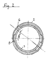
- a storage container is for tennis balls according to one embodiment of the invention shown in Figure 1 (in section).
- the storage container (generally indicated by reference numeral 1) is made up of two body parts 2,3 made of a plastics material.
- the body parts are cylindrical in shape, hollow, and each have one open and one closed end.
- the inner diameter of a first body part 2 is approximately equal to the outer diameter of the second body part 3 enabling the second body part to be inserted into the first as a push fit and to slide therein in an axial direction.
- An arrangement of grooves 5,6 and complementary projections 8 are provided on the first 2 and second 3 body parts respectively to enable the body parts to be fixed in a chosen interlocked position as will be described below.
- the body parts define a storage chamber 9 when in the interlocked position.
- a seal arrangement (generally indicated by reference numeral 10) is provided between the inner wall of the first body part and the outer wall of the second body part so as to substantially prevent the escape of gas from the storage chamber 9.
- the seal arrangement is made up of three O-rings 11 made of rubber. Three spaced shallow annular grooves are provided on the inner wall of the first body part 2 and on the outer wall of the second body part 3 to accommodate the O-rings.
- the inner wall of body part 2 has two longitudinal grooves 5 formed therein at opposite sides thereof, each beginning at the open end of body part 2 and ending in a short transverse groove 6 (thus forming an L-shape overall.
- the length of each transverse groove is approximately twice the width of the corresponding longitudinal groove.
- the second body part 8 has two projections 8 formed on opposite sides of the outer wall thereof and located roughly halfway along its length.
- the width of each projection is slightly less than the width of a corresponding longitudinal groove on the first body part and thus the projections can be accomodated in and slide along the longitudinal grooves when the second body part is inserted into the first body part.
- the length of the longitudinal grooves 5 determines the maximum distance of travel of the projections 8 and thus sets a maximum distance along the first body part 2 which the second body part 3 can travel (ie the point of maximum overlap, or interlock, of the body parts).
- transverse grooves 6 enable the two body parts to be fixed in an interlocked position by a simple rotation of one body part relative to the other.
- the storage container described above may be used to store tennis balls as follows. This description assumes that the container is initially empty, and that the two body parts are completely disengaged from one another. A number of tennis balls may be placed within second body part 3 to rest as shown in dashed lines in Figure 1. The first body part 2 is then presented to the second body part 3 with the longitudinal grooves 5 in alignment with the projections 8. The two body parts are then pushed together so that the second body part passes inside the first body part.
- the sealing arrangement prevents the escape of air which has been trapped between the two body parts and thus as the second body part is pushed further inside the first body part the pressure in the storage chamber 9 increases.
- one body part may be twisted to engage projections 8 in transverse grooves 6.
- the storage container described above can develop an excess pressure (ie pressure above atmospheric) of 6 to 18 pounds per square inch within the storage chamber; this is quite sufficient to replenish the internal gas pressure of partially depressurized tennis balls placed therein.
- an excess pressure ie pressure above atmospheric
- the above described embodiment may be modified to include a plug portion on one of the body parts extending into the storage chamber so as to contact the objects held therein and prevent them from moving about.
- a plug position is shown in Figure 1 in dotted lines referenced by the numeral 15.
- Alternative embodiments of the invention may have retaining arrangements different from that described above.
- the number of projection/groove pairs may be altered, the projections need not be located on the inner body part but can be located on the outer body part with corresponding grooves provided in the inner body part, and a mixture of grooves and projections may be provided on one body part with a corresponding mixture of projections and grooves on the other.
- embodiments of the invention can incorporate retaining arrangements which allow the body parts to be retained in more than one relative position. This may be achieved by providing a plurality of transverse grooves in communication with and spaced along the or each longitudinal groove.
- a screw thread may be provided on the outer wall of the inner body part and the inner wall of the outer body part so that the body parts will be retained in position by a relative rotation which causes the screw threads to engage.
- This latter construction can be used in combination with an end seal provided on the inside surface of the closed end of the outer body part so that as the screw thread is engaged because the inner body part advances a little further inside the outer body part the end of the inner body part will contact, and form a seal against, the end seal.
- each body part may have a smooth surfaced portion and a threaded portion so that a "push and twist" motion is required.
- An arrangement of this type is shown in Figure 3.
- FIG. 3 The embodiment of the invention shown in Figure 3 is a container for tennis balls and the like again comprising first and second body parts 22,23. Both body parts 22,23 are generally cylindrical each having one closed end and one open end.
- the first body part 22 has a first portion 22a adjacent the closed end with a generally smooth inner surface and a second portion 22b with a screw thread on at least part of its inner surface.
- the second body part 23 has a first portion 23a having a smooth outer surface and a second portion 23b adjacent the closed end having a screw thread on at least part of its outer surface.
- the screw threads on the respective second portions 22b 23b are arranged to cooperate in a manner to be described below.
- the outer diameter of the first portion 23a of the second body part is approximately equal to the inner diameter of the first portion of the first body part so that the portion 23a can be received in the portion 22a as a push fit.
- the seal is located in a channel 25 provided in the outer surface of the portion 23a.
- a second seal 26 is located on the end wall of the first body part 22, preferably in the form of a gasket.
- the container illustrated in Figure 3 is operated as follows: A number of tennis balls may be placed in the first body part 23 to rest on its closed end. The second body part is then presented to the first body part so that its first portion 23a slides within the second portion 22b of the first body part. The first and second body parts are pushed together in the axial direction until the portion 22a meets the portion 23a in the region X shown in the drawing. The seal 24 then seals the surfaces of the respective body portions 22a and 23a together. The two body parts are pushed together a little further until the screw threads meet and the parts are then rotated relative to each other so that the screw threads engage and the two parts cannot move axially apart.
- the body parts are dimensioned such that the second body part can be screwed into the first until its annular edge 23c abuts against the closed end face of the first body part.
- the seal 26 is arranged so that the edge 23c seats on the seal so that when the container is fully closed fluid cannot escape between the edge 23c and the body part 22. Because the seal 26 is located inside the container it is less likely to be damaged in use than the seal 24. It is possible for the seal 24 to be damaged so that although pressure can be built up within the container, it escapes over a prolonged period. The additional seal is provided to prevent the escape of fluid once the high pressure has been built up.
- a storage container embodying the invention may be selected to enable a different number of tennis balls to be stored therein ranging from a single ball to a relatively large number of balls stacked in layers and/or columns.
- embodiments of the invention adapted for storing objects other than tennis balls will be constructed of appropriate dimensions.
- Preferred embodiments of the invention in which the sealing arrangement uses O-rings are not limited to the numbers and dispositions of O-rings as shown above. However it has been found that the sealing arrangement works particularly well for higher pressures in the storage chamber when the sealing arrangement consists of one or more O-rings located as near as possible to the end of the inner body part (i.e. the end which is inside the outer body part).
- Embodiments of the invention requiring different pressure values in the storage chamber may be made of different materials, e.g. steel.
Landscapes
- Health & Medical Sciences (AREA)
- General Health & Medical Sciences (AREA)
- Physical Education & Sports Medicine (AREA)
- Packaging Of Annular Or Rod-Shaped Articles, Wearing Apparel, Cassettes, Or The Like (AREA)
- Packages (AREA)
Applications Claiming Priority (2)
| Application Number | Priority Date | Filing Date | Title |
|---|---|---|---|
| GB8812930 | 1988-06-01 | ||
| GB888812930A GB8812930D0 (en) | 1988-06-01 | 1988-06-01 | Storage container for tennis balls &c |
Publications (2)
| Publication Number | Publication Date |
|---|---|
| EP0345054A2 true EP0345054A2 (de) | 1989-12-06 |
| EP0345054A3 EP0345054A3 (en) | 1990-11-28 |
Family
ID=10637869
Family Applications (1)
| Application Number | Title | Priority Date | Filing Date |
|---|---|---|---|
| EP19890305509 Withdrawn EP0345054A3 (en) | 1988-06-01 | 1989-06-01 | Storage container for tennis balls and the like |
Country Status (2)
| Country | Link |
|---|---|
| EP (1) | EP0345054A3 (de) |
| GB (2) | GB8812930D0 (de) |
Cited By (2)
| Publication number | Priority date | Publication date | Assignee | Title |
|---|---|---|---|---|
| AT396335B (de) * | 1991-07-05 | 1993-08-25 | Smk Metall Und Kunststoffwaren | Verfahren, verpackung und einrichtung zum vorraetighalten und zur ausgabe von tennisbaellen |
| DE19741588A1 (de) * | 1997-09-20 | 1999-03-25 | Sunflex Sport Schnellbuegel & | Verfahren und Behälter zum Aufbewahren frischgeklebter Tischtennisschläger |
Families Citing this family (2)
| Publication number | Priority date | Publication date | Assignee | Title |
|---|---|---|---|---|
| GB2260957A (en) * | 1991-11-04 | 1993-05-05 | John Barrington Lay | Pressurising portable containers, e.g. containing tennis balls |
| US5311988A (en) * | 1992-09-29 | 1994-05-17 | Bronson Henry D | Pressurizing cap and method for using same |
Family Cites Families (4)
| Publication number | Priority date | Publication date | Assignee | Title |
|---|---|---|---|---|
| US3415357A (en) * | 1967-12-26 | 1968-12-10 | William J. Van Natter | Self-contained tennis ball storage container and pressurizing device |
| US4046279A (en) * | 1974-04-19 | 1977-09-06 | Hilti Aktiengesellschaft | Packing container for objects of variable lengths |
| FR2317185A1 (fr) * | 1975-07-09 | 1977-02-04 | Lee Chu | Etui pour balles de tennis |
| DE3738019A1 (de) * | 1987-11-09 | 1989-05-18 | Provera Gmbh | Tennisballbehaelter |
-
1988
- 1988-06-01 GB GB888812930A patent/GB8812930D0/en active Pending
-
1989
- 1989-06-01 GB GB8912572A patent/GB2219280B/en not_active Expired - Lifetime
- 1989-06-01 EP EP19890305509 patent/EP0345054A3/en not_active Withdrawn
Cited By (3)
| Publication number | Priority date | Publication date | Assignee | Title |
|---|---|---|---|---|
| AT396335B (de) * | 1991-07-05 | 1993-08-25 | Smk Metall Und Kunststoffwaren | Verfahren, verpackung und einrichtung zum vorraetighalten und zur ausgabe von tennisbaellen |
| DE19741588A1 (de) * | 1997-09-20 | 1999-03-25 | Sunflex Sport Schnellbuegel & | Verfahren und Behälter zum Aufbewahren frischgeklebter Tischtennisschläger |
| DE19741588C2 (de) * | 1997-09-20 | 2000-05-25 | Sunflex Sport Schnellbuegel & | Verfahren und Vorrichtung zur Verzögerung der Ausgasung bei einem frischgeklebten Tischtennisschläger |
Also Published As
| Publication number | Publication date |
|---|---|
| GB2219280A (en) | 1989-12-06 |
| GB2219280B (en) | 1992-10-21 |
| GB8812930D0 (en) | 1988-07-06 |
| GB8912572D0 (en) | 1989-07-19 |
| EP0345054A3 (en) | 1990-11-28 |
Similar Documents
| Publication | Publication Date | Title |
|---|---|---|
| US4760865A (en) | Container valve | |
| CA2151832A1 (en) | Improvements in Injection Devices | |
| US3675825A (en) | Self cleaning valve | |
| CA2127640A1 (en) | Two-way valve for a tap of a compressed or liquefied gas cylinder, and tap provided with such a valve | |
| GR3035796T3 (en) | Injection cartridge. | |
| EP0345054A2 (de) | Behälter zur Lagerung von Tennisbällen und ähnlichem | |
| EP0199900A3 (en) | Dispenser for tablets | |
| CA2261134A1 (en) | Syringes | |
| AU8649782A (en) | Cylindrical random or statistical packing | |
| GEP20001899B (en) | Injection Cartridge | |
| US4392589A (en) | Multiple-tube dispenser | |
| US3897874A (en) | Pressurized storage container | |
| US4452002A (en) | Magazine filling guide | |
| US3861570A (en) | Variable spray rate aerosol valve construction | |
| CA2150253A1 (en) | Injection cartridge | |
| JPS56135629A (en) | Oil-pressure type drop hammer | |
| JP2001182898A (ja) | ガスボンベ用バルブ装置 | |
| SU1661069A1 (ru) | Пробка-сапун | |
| WO1995009785A1 (en) | Product dispensing container with a double piston | |
| KR200338804Y1 (ko) | 주사기형 케이스 | |
| US3958728A (en) | Orthopedic bandage core | |
| KR100354605B1 (ko) | 전자제품용 코드릴 조립체의 파워코드 안내장치 | |
| CN1052288A (zh) | 带有推挤料剂用的活塞组件的撒布器 | |
| JPS5614609A (en) | Fluid cylinder capable of maintaining stop position | |
| KR820001129Y1 (ko) | 완구차의 탄발 장치 |
Legal Events
| Date | Code | Title | Description |
|---|---|---|---|
| PUAI | Public reference made under article 153(3) epc to a published international application that has entered the european phase |
Free format text: ORIGINAL CODE: 0009012 |
|
| AK | Designated contracting states |
Kind code of ref document: A2 Designated state(s): DE FR GB IT |
|
| PUAL | Search report despatched |
Free format text: ORIGINAL CODE: 0009013 |
|
| AK | Designated contracting states |
Kind code of ref document: A3 Designated state(s): DE FR GB IT |
|
| STAA | Information on the status of an ep patent application or granted ep patent |
Free format text: STATUS: THE APPLICATION IS DEEMED TO BE WITHDRAWN |
|
| 18D | Application deemed to be withdrawn |
Effective date: 19910529 |