EP0344901B1 - Bandkassette mit Rückspulsteuerungsmechanismus - Google Patents
Bandkassette mit Rückspulsteuerungsmechanismus Download PDFInfo
- Publication number
- EP0344901B1 EP0344901B1 EP89303898A EP89303898A EP0344901B1 EP 0344901 B1 EP0344901 B1 EP 0344901B1 EP 89303898 A EP89303898 A EP 89303898A EP 89303898 A EP89303898 A EP 89303898A EP 0344901 B1 EP0344901 B1 EP 0344901B1
- Authority
- EP
- European Patent Office
- Prior art keywords
- spool
- disc
- housing
- engagement
- rotation
- Prior art date
- Legal status (The legal status is an assumption and is not a legal conclusion. Google has not performed a legal analysis and makes no representation as to the accuracy of the status listed.)
- Expired - Lifetime
Links
- 230000007246 mechanism Effects 0.000 title claims abstract description 61
- 230000008878 coupling Effects 0.000 claims abstract description 27
- 238000010168 coupling process Methods 0.000 claims abstract description 27
- 238000005859 coupling reaction Methods 0.000 claims abstract description 27
- 238000004804 winding Methods 0.000 claims abstract description 8
- 230000002093 peripheral effect Effects 0.000 claims description 9
- 230000007423 decrease Effects 0.000 claims 1
- 230000006835 compression Effects 0.000 description 5
- 238000007906 compression Methods 0.000 description 5
- 125000006850 spacer group Chemical group 0.000 description 4
- 230000000007 visual effect Effects 0.000 description 4
- 238000010276 construction Methods 0.000 description 2
- 238000000034 method Methods 0.000 description 2
- 241000237983 Trochidae Species 0.000 description 1
- 238000013016 damping Methods 0.000 description 1
- 230000000694 effects Effects 0.000 description 1
- 238000012986 modification Methods 0.000 description 1
- 230000004048 modification Effects 0.000 description 1
Images


Classifications
-
- G—PHYSICS
- G11—INFORMATION STORAGE
- G11B—INFORMATION STORAGE BASED ON RELATIVE MOVEMENT BETWEEN RECORD CARRIER AND TRANSDUCER
- G11B23/00—Record carriers not specific to the method of recording or reproducing; Accessories, e.g. containers, specially adapted for co-operation with the recording or reproducing apparatus ; Intermediate mediums; Apparatus or processes specially adapted for their manufacture
- G11B23/28—Indicating or preventing prior or unauthorised use, e.g. cassettes with sealing or locking means, write-protect devices for discs
- G11B23/287—Indicating or preventing prior or unauthorised use, e.g. cassettes with sealing or locking means, write-protect devices for discs by mechanical lock
-
- G—PHYSICS
- G11—INFORMATION STORAGE
- G11B—INFORMATION STORAGE BASED ON RELATIVE MOVEMENT BETWEEN RECORD CARRIER AND TRANSDUCER
- G11B15/00—Driving, starting or stopping record carriers of filamentary or web form; Driving both such record carriers and heads; Guiding such record carriers or containers therefor; Control thereof; Control of operating function
- G11B15/18—Driving; Starting; Stopping; Arrangements for control or regulation thereof
- G11B15/46—Controlling, regulating, or indicating speed
- G11B15/50—Controlling, regulating, or indicating speed by mechanical linkage, e.g. clutch
-
- G—PHYSICS
- G11—INFORMATION STORAGE
- G11B—INFORMATION STORAGE BASED ON RELATIVE MOVEMENT BETWEEN RECORD CARRIER AND TRANSDUCER
- G11B23/00—Record carriers not specific to the method of recording or reproducing; Accessories, e.g. containers, specially adapted for co-operation with the recording or reproducing apparatus ; Intermediate mediums; Apparatus or processes specially adapted for their manufacture
- G11B23/02—Containers; Storing means both adapted to cooperate with the recording or reproducing means
- G11B23/04—Magazines; Cassettes for webs or filaments
- G11B23/08—Magazines; Cassettes for webs or filaments for housing webs or filaments having two distinct ends
- G11B23/087—Magazines; Cassettes for webs or filaments for housing webs or filaments having two distinct ends using two different reels or cores
- G11B23/08707—Details
- G11B23/08721—Brakes for tapes or tape reels
Definitions
- This invention relates to tape cassettes.
- the invention relates to a tape cassette which has a controlled access rewinding mechanism.
- EP-A-0 064 859 discloses a tape cassette with a limited access rewind system.
- a member pivotally mounted proximate the side of the supply reel comprises a plate which frictionally engages the underside of the reel.
- the member also comprises a reel locking finger. Forward winding causes the member to rotate in order to bias the locking finger to an inoperative position.
- the frictional engagement of the plate with the reel rotates the reel locking finger into engagement with one of the teeth of the reel thereby jamming the reel.
- a cooperating arm pushes the member out of locking position so the tape may be rewound.
- This mechanism includes a series of notches formed along the peripheral edge of the lower side wall of the spool and a latch mechanism which will engage these notches to prevent rotation of the spool.
- This latch mechanism is disengaged by a rod which is incorporated into a VCR which will extend through the bottom wall of the housing and will engage the latch members to move them out of engagement with the spools.
- This structure cannot be used in a tape cassette of the type of the present invention in which the lower side wall of the spool acts as an engagement member for engaging a one-way clutching mechanism.
- a tape cassette having a housing and a pair of spools located in the housing, a first of said spools being a take-up spool which is mounted in the housing for rotation about its axis in a first direction to wind and in a second direction to unwind a tape from or onto the other spool, an engagement member mounted in the housing, and a one-way coupling arranged to communicate between the engagement member and the take-up spool, said coupling means engaging automatically in the unwinding direction and releasing automatically in the winding direction, and means allowing the spool to be rewound, characterised in that the engagement member is mounted in the housing for rotation about the axis of the take-up spool, the one-way coupling prevents rotation of the spool relative to the engagement member when engaged and permitting free rotation of the spool relative to the engagement member when released, and by a locking means in said housing, said locking means being operable to engage said engagement member to secure it against rotation in either
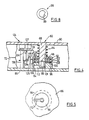
- the reference numeral 10 refers generally to a take-up spool.
- the take-up spool 10 consists of an upper side wall disc 12, a lower side wall disc 14 and a central hub which is generally identified by the reference numeral 16.
- the central hub 16 has an outer cylindrical portion 18 which functions as a winding drum on which the tape which is to be supported on the spool 10 is wound.
- a plurality of ribs 20 extends between the outer cylindrical portion 18 and an intermediate cylindrical portion 22.
- the intermediate cylindrical portion 22 is formed with a top wall 24 which has a projection 26 and a plurality of studs 25 which extends through an opening 28 and a plurality of openings 29 in the upper side wall disc 12.
- a hub insert 30 is mounted in the intermediate cylindrical portion 22 and is formed with a plurality of longitudinally extending ribs 32 which are arranged to engage the spindle of the drive shaft.
- a circular retaining ring 34 serves to connect the intermediate cylindrical portion and hub insert 30 in the interlocked configuration shown in Figure 2.
- a conventional tape anchor 19 is provided for the purposes of attaching the leader tape (not shown) to the central hub 16.
- the tape anchor 19 is proportioned to fit in a close fitting relationship within the slot 19b which is formed in the central hub 16.
- a torque limiting clutch is provided which will operate to effectively disguise the fact that the tape has been fully unwound onto the take-up spool.
- a second insert 17 is located in a notch 17a which is formed in the outer cylindrical portion 18 of the central hub 16.
- a resilient detent in the form of a leaf spring 21 is mounted on the insert 17 and projects therefrom. As shown in Figure 11 of the drawings, when the insert 17 is located in the notch 17a, the leaf spring 21 will extend into one of the notches 31 which is formed in the hub insert 30 of the central hub 16.
- the leaf spring 21 forms the drive coupling between the central hub 16 and the hub insert 30. If the central hub 16 cannot rotate because of an end of tape condition, the leaf spring 21 can be deflected so as to be displaced out of successive notches 31 to permit the hub insert 30 to be rotatably driven by the motor which drives the take-up spool. The amount of torque that can be transmitted through the hub insert 30 is determined by the degree of flexibility of the leaf spring 21.
- the transparent leader which is customarily used to activate the rewind mechanism is replaced with a heavy leader.
- the conventional leader normally has a thickness of about 0,025 mm (.001") whereas the leader which we prefer to use has a thickness of about 0,125 mm (.005") to 0,25 mm (.010”) and a length of go to 120 cm (3' to 4').
- An engagement member, consisting of engagement disc 38 is connected to the spool 10 by means of a one-way coupling which is generally identified by the reference numeral 40.
- the one-way coupling 40 consists of a locking ring 42 which is formed with an annular groove 44 in which the inner edge of the lower side wall disc 14 is mounted and held fast.
- the locking ring 42 has a flange 46 which projects radially outwardly from its lower edge.
- a roller cage 48 is mounted on the disc 38 and extends circumferentially around the ring 42 in a spaced relationship thereto.
- the roller cage 48 has a flange 50 which extends radially inwardly thereof and rests upon the flange 46.
- a plurality of recesses 52 are formed at circumferentially spaced intervals around the roller cage 48.
- Each recess 52 has a lip portion 53 which cooperates with the flange 46 to form a bottom wall.
- Each recess also has a ramp face 54 which is inclined inwardly toward the inner locking 42.
- a roller 56 is located in each recess 52 and is proportioned so as to be freely rotatable when located in the large end of the recess 52 and to act as a wedge which will serve to secure the locking ring 42 against rotation with respect to the roller cage 48 when located toward the narrow end of the recess 52.
- the roller cage 48 is mounted on and secured against rotation with respect to the engagement disc 38.
- the one-way coupling 40 will permit rotation of the spool in the direction of the arrow A (Fig.1) while preventing rotation in the direction of the arrow B. If, however, the engagement disc 38 is free to rotate, the entire assembly of spool 10 and engagement disc 38 may rotate freely in the direction of the arrow A or in the direction of the arrow B.
- rollers 56 are simple cylindrical shaped rollers which are merely confined by the walls of the recess in which they are located.
- the diameter of the lower side wall disc 14 is substantially less than the diameter of the engagement disc such that a marginal edge portion 38a of the engagement disc will project beyond the outer edge of the disc 14.
- a plurality of notches 60 are formed in the marginal edge portion 38a and extend radially inwardly. The notches 60 function as locking openings in the peripheral edge portion 38a as will be described hereinafter.
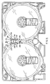
- the reference numeral 62 refers generally to a tape cassette housing constructed in accordance with an embodiment of the present invention.
- the cassette has a front edge 68 along which a tape is guided as it is transferred from one spool to the other and a back edge 70 which extends parallel to the front edge and tangentially with respect to the spool mounting compartments.
- the spool mounting compartments have side wall portions 72 and 74 which converge in a direction away from the back edge 70 of the housing and are connected to one another at their inner end.
- a third compartment 76 is formed between the back edge 70 and the side wall portions 72 and 74. This third compartment serves to accommodate the locking mechanism which is generally identified by the reference numeral 80.
- An opening 78 is formed in the side wall 72 to provide access to the compartment 64.
- access to the locking mechanism 80 is achieved through a passage 84 which is formed in the bottom wall 86 of the tape cassette 62.
- the locking mechanism 80 is in the form of a rotary combination lock which has a central post 88 which is formed integrally with the top wall 90 of the cassette housing 62 and has a concentric hole 89.
- Two lock discs 92 and 94 and a lock drive disc 96 are mounted for rotation on the shaft 88.
- Spacers 98 and 100 consist of an annular ring with an internal tongue 99 (Fig.8). The tongue 99 locates in groove 101 of central post 88 (Fig.4) and prevents rotation of the spacer about axis of central post 88.
- Spacers 98 and 100 serve to provide narrow gaps between adjacent lock discs and to prevent rotation by friction between lock drive disc 96 and lock disc 94 and between lock discs 94 and 92.
- a pin 102 projects downwardly from the lock disc 92 and a pin 104 projects upwardly from the lock disc 94.
- a pin 106 projects downwardly from the lock disc 94 and the pin 108 projects upwardly from the lock drive disc 96.
- a radially extending slot 112 is formed on the bottom face of lock drive disc 96.
- a compression spring 114 bears against the top wall 90 and the lock disc 92 and serves to maintain the discs in the position shown in Figure 4.
- a drive head is located beneath lock drive disc 96 and a drive pin extends into the slot 112.
- the drive head When the drive head is rotatably driven in a first direction, it will drive the lock drive disc 96 until the pin 108 strikes the pin 106 and thereafter both lock drive disc 96 and lock disc 94 will be rotatably driven and when the pin 104 contacts the pin 102, all three discs will be rotatably driven.
- the lock disc 92 has a slot 116 which extends radially inwardly from its peripheral edge.
- the lock disc 94 has a slot 118 and the lock drive disc 96 has a slot 120 which also extends radially inwardly.
- the slot 120 and the lock drive disc 96 has a side edge 122 which forms a ramp which serves to unseat the locking pin as will be described hereinafter.
- a locking lever arm 124 is provided for the purposes of releaseably locking the engagement disc 38 against rotation.
- the locking lever arm is illustrated in Figures 4, 9 and 10 of the drawings to which reference is now made.
- the locking lever arm 124 consists of two pivot arms 125 and 127 which are arranged one above the other and pivotally mounted on the shaft 126.
- a finger 130 is formed on the arm 125 and is arranged to project laterally toward the engagement disc 38 so as to extend into a notch 60 as shown in Figure 3 of the drawings in use.
- a torsion spring 134 extends around the shaft 126 and has one end bearing against the lever arm 125 and its other end bearing against the pin 136 which is formed integrally with the housing.
- the locking lever arm 127 is also pivotally mounted on the shaft 126 and has a locking pin 132 mounted on one end thereof which extends vertically downwardly therefrom.
- the locking pin 132 is proportioned to fit within each of the notches 116, 118 and 120 of the locking discs.
- a small torsion spring 135 extends around the shaft 126 and has one end bearing against the lever arm 127 and its other end bearing against the pin 136.
- the biasing springs 134 and 135 are arranged to operate in opposite directions. The spring 135 urges the lever arm 127 toward the lock discs and the spring 134 urges the arm 125 toward the edge of the spool.
- the torsion spring 135 is, however, substantially stronger than the torsion spring 134 with the result that in the condition where the pin 132 is aligned with the notches of the lock discs, the arm 127, the spring 135, will act to overcome the spring 134 to move the arm 125 away from the spools.
- the arm 125 has a small lug 129 which projects upwardly therefrom and is located in an outwardly overlying relationship with respect to the radially extending portion of the arm 127 (Fig.4).
- the drive head when operably positioned as will be described hereinafter and rotatably driven, it will initially be powered so that it rotatably drives the lock discs in a counter-clockwise direction from the position shown in Figure 3 of the drawing to engage the entire disc stack as described previously.
- the unlocking mechanism After sufficient rotation in this counter-clockwise direction, the unlocking mechanism will, as will be described hereinafter, index the disc stack to an index point common to the cassette 62 and lock release mechanism 144, and will then initiate the unlocking procedure after receiving unlocking directions from unlock code by causing lock disc 92 to be driven to the position where its slot 116 is aligned with the locking pin 132. The direction of rotation of the drive head will then be reversed.
- the pin 104 will move away from the pin 102 and the upward lock disc 98 will remain stationary while the lock disc 94 will be rotated until its slot 118 is aligned with the locking pin 132.
- This procedure will then be repeated by again reversing the direction of rotation of the drive head so that the drive head will serve to move the lock drive disc 96 while the lock discs 92 and 94 remain in the aligned position.
- the lock drive disc will then be positioned with its slot 120 aligned with the locking pin 132 at which time the locking pin 132 will move inwardly of the aligned slots of the lock discs under the influence of the spring 134. This will simultaneously cause the finger 130 to be withdrawn from the notch 60 of the engagement disc, thus releasing the engagement disc 38 for free rotation to permit rewinding of the spool.
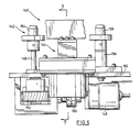
- the rewinding mechanism which is generally identified by the reference numeral 140 in Figures 6 and 7, includes a spool drive mechanism 142 and a lock release mechanism 144.
- the spool drive mechanism 142 is constructed so as to be the same as that illustrated in US-A-4,632,335 dated December 30, 1986.
- This mechanism includes a drive shaft 146 which is driven by a motor 148 through a coupling 150 and a gear train 152.
- the driven head 154 is adapted to fit within the free-fitting spool of the cassette in a conventional manner.
- the head 156 which is mounted on the post 158 is a follower which is mounted for free rotation about its longitudinal axis.
- the spool drive mechanism 142 and the lock release mechanism 144 are each supported on a platform 160.
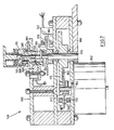
- the power source for the lock release mechanism 140 is a reversable DC stepper motor 162 which has an output shaft 164.
- a disc 166 is mounted for rotation with the shaft 164. The outer peripheral edge of the disc 166 passes through a slot 168 which is formed in a visual sensor device 170.
- a radial slot (not shown) is cut in to the marginal edge of the disc 166 and the presence of this slot is detected by the sensor 170.
- a gear wheel 172 is also mounted for rotation with the shaft 164 and meshes with a gear wheel 174 which is mounted on the drive shaft 176 of the lock release mechanism.
- a further disc 178 is mounted on the drive shaft 174 for rotation therewith. The marginal edge portion of the disc 178 extends into the slot 180 which is formed in the second visual sensor 182.
- the lock drive head is in the form of a cylindrical shaped head member 184 which is mounted on the upper end of the drive shaft 176.
- the head portion 184 has a shoulder 186 and the shaft 176 has a shoulder 188 which is located opposite the shoulder 186.
- a compression spring 190 is located between the shoulders 186 and 188 and normally serves to urge the head portion to an elevated position with respect to the shaft 176.
- a pin 192 extends through the shaft 176 and the head portion 184 and serves to connect the head portion 184 to the shaft 176 for rotation therewith.
- the pin 192 is mounted in a slot 191 which extends longitudinally of the head 184 so as to permit the longitudinal movement of the head 184 with respect to the shaft 176.
- a retaining ring 193 serves to limit the upward motion of the drive head 184.
- a visually detectable band 194 is formed on the outer face of the head 184 and extends circumferentially thereof.
- a third visual sensor 198 is mounted on a support platform 199 and serves to generate a signal which indicates when the band 194 is aligned with the visual sensor thereby indicating that the head 184 is operably positioned for the purposes of rotatably driving the combination lock.
- the head 184 has a drive pin 196 which is arranged to project into the radial slot 112 of the lock drive disc 96.
- the cassette which is to be rewound is positioned with the take-up spool 10 mounted on the head 156 and the supply spool, which is to be driven in the rewind direction A, is mounted on the driven head 154.
- the axis of the drive shaft 176 of the lock release mechanism 144 will be aligned with the axis of the locking mechanism 80 by means of a recess 89 of which is formed in the central post 88 centering itself on drive shaft 176. If the drive pin 196 of the head 184 is not aligned with the slot 112, the head 184 will be forced downward to compress the spring 190.
- the stepper motor 162 is then activated to rotatably drive the drive shaft 176 through the gears 172 and 174.
- the drive pin 197 When the drive pin 197 is aligned with the slot 112, it will enter the slot 112 and the head 184 will be raised by the compression spring 190.
- the sensor 196 will generate a signal indicating the engagement of the lock drive disc 96 and the head 184 when the head is arranged so that the visually detectable band 194 can be detected by the sensor 198.
- the drive shaft 176 is now coupled to the lock drive disc 96 of the lock mechanism. Further rotation of the shaft 176 will occur in the counter-clockwise direction when viewed in the position shown in Figure 3.
- the stepper motor 162 will continue to rotatably drive the engaged disc stack for a number of motor steps corresponding to first number in the unlock code from the index point at which the slot 116 of the lock disc 92 is aligned with the locking pin 132.
- the direction of rotation of the step motor is now reversed and it will operate to drive the shaft 176 in a clockwise direction, a number of motor steps corresponding to the second number in the unlock code.
- the lock drive disc 96 will initially be driven in the clockwise direction while the lock discs 94 and 92 will remain stationary.
- the lock disc 94 When the pin 108 which is carried by the lock drive disc 96 engages the pin 106 of the lock disc 94, the lock disc 94 will be driven in the clockwise direction at which point, after the motor has finished performing the number of steps required, slot 118 of the lock disc 94 is aligned with the locking pin 132.
- the direction of the stepper motor is again reversed and performs a number of motor steps corresponding to the third number of the unlock code at which point the slot 120 of the lock drive disc 96 is aligned with the locking pin 132 at which point the locking pin 132 will enter the slots of the locking disc stack and thereby remove the locking pin 132 from the notch 60 of the spool 10.
- the drive motor 148 is activated to rotatably drive the driven head 154 to rewind the tape from the spool 10 onto the supply spool.
- the stepper motor 162 is again activated to rotatably drive the drive shaft in the counter-clockwise direction. Rotation in this direction will cause the ramp surface 122 of the notch 120 to unseat the locking pin 132 to drive locking lever arm 124 towards the engagement disc 38. If notch 60 is in proper alignment finger 130 will enter notch 60 and lock the engagement disc 38. If the notch 60 is not aligned with the finger 130, the movement of the finger 130 will be interrupted when it makes contact with the disc.
- the structure of the spool 10 has been simplified in that it does not incorporate a one-way coupling mechanism which functions as a clutch and which must be released to permit rewinding.
- the component which is locked in order to prevent rewinding is the engagement disc and this disc in combination with the one-way coupling 42 provides a controlled access rewinding system in a spool of a relatively simple construction.
- the unlocking mechanism is of a relatively simple construction which is capable of accommodating various different combinations.
- the number of discs which are used in the locking mechanism need not necessarily be limited to three.
- the number of pins in each disc need not be limited to two.
- the initial direction of rotation of the locking mechanism need not be in the counter-clockwise direction. The initial direction depends on the number of discs in the stack and the direction of the ramp formed on the locking drive disc.
- the tape cassette of the present invention can be operated as a normal cassette which will permit rewinding as required merely by leaving the locking mechanism in the unlock position. In this position, the engagement mechanism is always free to rotate. The engagement mechanism is not capable of operating in the locking mode unless the locking mechanism is located in the lock position.
- a plurality or notches 200 are formed at spaced intervals about the peripheral edge of the upper side wall 12.
- a cap 202 is mounted in a passage 204 which is formed in the top wall 206 of the housing of the cassette.
- the cap 202 is formed with a recess 208 which has a shoulder portion 210 extending radially thereof.
- a hollow column 212 which is formed integrally with the wall 214 of the lower cassette housing segment has its upper end bearing against the shoulder 210.
- the column 212 is formed with a slide passage 216 which has a shoulder 218 at its lower end.
- the slide passage 216 opens through the bottom wall of the cassette at lower end of the column 212.
- a slide member 222 is slidably mounted in the column 212 and a compression spring 224 normally urges the slide member 222 to the position in which it bears agains the shoulder 218 as shown in Figure 15.
- a longitudinally extending slot 250 is formed in the slide member 222 into which a tongue 252 which is formed on the inner wall of the hollow column 212 extends. This tongue and slot serve to permit longitudinal movement of the slide member 222 while preventing rotation of the slide member 222.
- a pair of latching members 226 are mounted on posts 228.
- the latching members 226 have latching arm 230 extending radially therefrom which has a tooth 232 at the outer end thereof.
- the teeth 232 are proportioned and arranged to extend into the notches 200 to lock the spools against rotation.
- the latching members 226 also have actuator arms 234 which extend radially outwardly therefrom. The actuator arms 234 extend through a passage 236 which is formed in the side wall of the column 212 into the path of travel of the slide member.
- the slide member 222 is formed with a recess 240 which has an angularly inclined ramp face 242 which extends inwardly and upwardly from a shoulder 244 which is located at the lower end of the recess 240.
- the slide member 222 is elevated to the position shown in Figure 17 by means of a rod 246 which is commonly provided in existing VCR equipment for the purposes of raising the corresponding slide member previously used.
- a rod 246 which is commonly provided in existing VCR equipment for the purposes of raising the corresponding slide member previously used.
- the arms 234 will be deflected by contact with the ramp face 242 and will eventually assume a position bearing against the shoulder 244.
- the shoulder 244 forms a rigid stop which limits the inward movement of the arms 234 in a manner which provides a more stable support than that which would be provided by the inclined ramp face 242.
Landscapes
- Engineering & Computer Science (AREA)
- Computer Security & Cryptography (AREA)
- Automatic Tape Cassette Changers (AREA)
- Packaging Of Annular Or Rod-Shaped Articles, Wearing Apparel, Cassettes, Or The Like (AREA)
- Winding Of Webs (AREA)
Claims (10)
- Bandkassette mit einem Gehäuse (62) und einem im Gehäuse angeordneten Paar von Spulen, wobei eine erste der genannten Spulen eine Aufwickelspule (10) ist, welche im Gehäuse um ihre Achse in eine erste Richtung zum Aufwickeln und in eine zweite Richtung zum Abwickeln eines Bandes von oder auf die andere Spule drehbar gelagert ist, mit einem Einklinkelement (38) im Gehäuse und einer Einwegkupplung (48, 56), eingerichtet für das Zusammenwirken zwischen dem Einklinkelement und der Aufwickelspule, wobei die genannten Kupplungsmittel in Abwicklungsrichtung automatisch einklinken und in Aufwickelrichtung automatisch loslassen, und mit Mitteln, welche einen (...Rücklauf...) der Spule erlauben, dadurch gekennzeichnet, dassa) das Wirkelement (38) im Gehäuse um die Achse der Aufwickelspule (10) drehbar gelagert ist,b) die Einwegkupplung (48, 56) ein Drehen der Spule relativ zum Einklinkelement verhindern wenn eingeklinkt und ein freies Rotieren der Spule relativ zum Einklinkelement erlauben wenn gelöst, und dassc) im genannten Gehäuse Verriegelungsmittel (80) vorgesehen sind, welche zum Einklinken des genannten Einklinkelements (38) betätigbar sind, um es gegen Rotation in jede Richtung um die Achse der Aufwickelspule (10) zu sichern und dadurch (i) ein Drehen der Aufwickelspule zu verhindern als Resultat des automatischen Einklinkens der Einwegkupplung, wenn ein Versuch gemacht wird, die Aufwickelspule relativ zum Einklinkelement in der Abwicklungsrichtung zu drehen, und (ii) ein Drehen der Aufwickelspule zu erlauben als Resultat einer freien Rotation der Aufwickelspule ermöglicht durch die Kupplung, wenn die Aufwickelspule relativ zum Einklinkelement in der Aufwickelrichtung gedreht wird, und welche Verriegelungsmittel des Einklinkelements zum Ausklinken betätigbar sind, um eine freie Rotation der Spule um ihre Achse zwecks Abwicklung der Spule zu ermöglichen.
- Bandkassette nach Anspruch 1, dadurch gekennzeichnet, dass die Verriegelungsmittel (80) durch ein mit einem Schlüssel betätigbares Schloss gebildet sind.
- Bandkassette nach Anspruch 1, dadurch gekennzeichnet, dass die Verriegelungsmittel (80) durch ein mit einem Schlüssel betätigbares Kombinationsschloss gebildet sind.
- Bandkassette nach Anspruch 1, dadurch gekennzeichnet, dass das genannte Einklinkelement (38) eine Wirkscheibe umfasst, in welcher eine Verriegelungsöffnung (60) gebildet ist, wobei die Verriegelungsmittel eine Sperre (130) umfassen, welche beweglich gelagert ist um in die Verriegelungsöffnung hinein und aus ihr heraus bewegbar zu sein, und einen Verriegelungsmechanismus, welcher betätigbar ist, um das Sperrglied in die Verriegelungsöffnung hinein und aus ihr heraus zu bewegen.
- Bandkassette nach Anspruch 4, dadurch gekennzeichnet, dass die Aufwikkelspule eine obere Seitenwandscheibe (12), eine untere Seitenwandscheibe (14) und eine zentrale Nabe (16) umfasst, wobei die untere Seitenwandscheibe einen Durchmesser hat, welcher geringer als derjenige der Wirkscheibe (38) ist, so dass ein peripherer Randteil der Wirkplatte radial über den Rand der unteren Seitenwandscheibe hinaus ragt, wobei die genannte Verriegelungsöffnung (60) die Form einer Kerbe hat, welche sich vom peripheren Rand der Wirkscheibe in den peripheren Randteil derselben erstreckt.
- Bandkassette nach Anspruch 5, dadurch gekennzeichnet, dass die Einwegkupplungsmittel als Rollenkupplung ausgebildet sind.
- Bandkassette nach Anspruch 1 mit spulenplazierenden Abteilen (64, 66), welche kreisförmig und im Gehäuse nebeneinander angeordnet sind, wobei die Kassette eine Frontseite (68) hat, entlang welchem das Band geführt ist, wenn es von einer Spule zur andern übertragen wird, und eine Rückseite (70), welche sich parallel zur Frontseite und tangential bezüglich der Spulenplazierungsabteilen erstreckt, wobei die Spulenplazierungsabteile Seitenwandteile (72, 74) haben, welche in Richtung weg von der Rückseite des Gehäuses konvergieren, weiter gekennzeichnet, durcha) ein drittes Abteil (76), welches zwischen der Rückseite der Kassette und den konvergierenden Seitenwandteilen der Spulenplazierungsabteile angeordnet ist,b) einen Verriegelungsdurchgang (78), sich öffnend vom genannten dritten Abteil durch ein erstes der genannten konvergierenden Seitenwandteile hindurch in das Spulenplazierungsabteil hinein, in welchem die Abwikkelspule angeordnet ist, wobei die genannten Verriegelungsmittel (80) im dritten Abteil angeordnet sind und eine Sperre (130) aufweisen, welche für eine Bewegung durch den genannten Verriegelungsdurchgang hindurch in und aus einer Wirkverbindung mit dem genannten Bremsglied gelagert ist.
- Bandkassett`e nach Anspruch 1 mit Spulenplazierungsabteilen (64, 66), welche kreisförmig und im Gehäuse nebeneinander angeordnet sind, wobei die Kassette eine Frontseite (68), entlang welcher das Band geführt ist, wenn es von der einen Spule auf die andere übertragen wird, und eine Rückseite (70) hat, welche sich parallel zur Frontseite und tangential bezüglich den Spulenplazierungsabteilen erstreckt, wobei die Spulenplazierungsabteile Seitenwandteile (72, 74) aufweisen, welche in Richtung weg von der Rückseite des Gehäuses konvergieren, wobei das Gehäuse obere und untere Seitenwände (206, 214) hat, wobei jede der Spulen eine obere und eine untere kreisförmige Seitenwand (12, 14) hat, welche benachbart zur oberen bzw. unteren Seitenwand des Gehäuses angeordnet sind, weiter gekennzeichnet durcha) ein drittes Abteil (76), welches zwischen der Rückseite der Kassette und den genannten konvergierenden Seitenwandteilen der Spulenplazierungsabteile angeordnet ist,b) eine Mehrzahl von Kerben (200), welche im äusseren peripheren Rand der oberen Seitenwand (12) jeder Spule in umfangsmässig beabstandeten Intervallen gebildet sind,c) ein Schieberglied (222), welches verschiebbar im genannten dritten Abteil (76) gelagert ist für eine Bewegung entlang eines Führungspfades (216) zwischen einer abgesenkten Position und einer angehobenen Position bezüglich der unteren Wand des Gehäuses,d) ein Paar von Verriegelungsarmen (226), wobei einer auf jeder Seite des genannten Schieberglieds angeordnet ist, wobei ein Verriegelungsarm jeder Spule zugeordnet ist, jeder Verriegelungsarm drehbar im genannten dritten Abteil gelagert ist für eine Bewegung zwischen einer ersten Position, in welcher er in einer Kerbe der zugeordneten Spule einliegt, um die Spule gegen Drehung zu verriegeln, und einer zweiten Position, in welcher er ohne Wirkverbindung mit der zugeordneten Spule ist,e) Vorspannmittel (248) um jeden des genannten Paars von Verriegelungsarmen bezüglich seiner ersten Position vorzuspannen,f) einen Betätigungshebelarm (234), welcher von jedem Verriegelungsarm in Richtung des genannten Schieberglieds vorragt für eine Bewegung mit seinem zugeordneten Verriegelungsarm zwischen ersten und zweiten Positionen in Erwiderung zur Bewegung der Verriegelungsarme zwischen deren ersten und zweiten Positionen, wobei die genannten Betätigungshebelarme sich in den genannten Führungspfad erstrecken zumindest wenn jeder des genannten Paars von Verriegelungsarmen in seiner ersten Position ist,g) eine Rampenfläche (242) auf dem genannten Schieberglied, wobei die genannte Rampenfläche vorgesehen ist, um die genannten Betätigungshebelarme einzuklinken, wenn das genannte Schieberglied zwischen der genannten abgesenkten und der genannten angehobenen Position hin und her geführt wird, um die genannten Betätigungshebelarme zwischen deren ersten und zweiten Positionen hin und her zu bewegen und dadurch deren zugeordnete Verriegelungsarme zwischen den ersten und zweiten Positionen hin und her zu bewegen, um deren zugeordneten Spulen gegen Rotation zu verriegeln und deren zugeordneten Spulen für eine Drehung loszulassen entsprechend dem geforderten Gebrauch.
- Bandkassette nach Anspruch 8, dadurch gekennzeichnet, dass die Weite des dritten Abteils (76) zusehends abnimmt zu einem engen inneren Ende, welches zwischen den Spulen angeordnet ist, wobei der genannte Führungspfad (216) nach aussen beabstandet ist vom genannten engen inneren Ende des dritten Abteils.
- Bandkassette nach Anspruch 9, dadurch gekennzeichnet, dass jeder Verriegelungsarm des genannten Paars von Verriegelungsarmen (226) sich von seiner Drehachse nach innen zum inneren Ende des dritten Abteils erstreckt in einer kompakten Anordnung, so dass ein wesentlicher Teil des dritten Abteils, welcher zwischen dem Spulenverriegelungsmechanismus und der genannten Seitenwand angeordnet ist, durch den Spulenverriegelungsmechanismus nicht besetzt ist und für andere Mechanismen zur Verfügung steht.
Priority Applications (1)
| Application Number | Priority Date | Filing Date | Title |
|---|---|---|---|
| AT89303898T ATE97255T1 (de) | 1988-06-03 | 1989-05-01 | Bandkassette mit rueckspulsteuerungsmechanismus. |
Applications Claiming Priority (2)
| Application Number | Priority Date | Filing Date | Title |
|---|---|---|---|
| CA000568640A CA1286273C (en) | 1988-06-03 | 1988-06-03 | Tape cassette having rewind control mechansim |
| CA568640 | 1988-06-03 |
Publications (3)
| Publication Number | Publication Date |
|---|---|
| EP0344901A2 EP0344901A2 (de) | 1989-12-06 |
| EP0344901A3 EP0344901A3 (de) | 1991-02-20 |
| EP0344901B1 true EP0344901B1 (de) | 1993-11-10 |
Family
ID=4138139
Family Applications (1)
| Application Number | Title | Priority Date | Filing Date |
|---|---|---|---|
| EP89303898A Expired - Lifetime EP0344901B1 (de) | 1988-06-03 | 1989-05-01 | Bandkassette mit Rückspulsteuerungsmechanismus |
Country Status (7)
| Country | Link |
|---|---|
| EP (1) | EP0344901B1 (de) |
| JP (1) | JPH02276078A (de) |
| AT (1) | ATE97255T1 (de) |
| AU (1) | AU3387989A (de) |
| CA (1) | CA1286273C (de) |
| DE (1) | DE68910583T2 (de) |
| ZA (1) | ZA893793B (de) |
Families Citing this family (3)
| Publication number | Priority date | Publication date | Assignee | Title |
|---|---|---|---|---|
| JP2616838B2 (ja) * | 1990-10-17 | 1997-06-04 | ティーディーケイ株式会社 | テープカセット |
| DE69126847T2 (de) * | 1990-11-30 | 1998-02-12 | Matsushita Electric Ind Co Ltd | Bandkassette |
| JP3700692B2 (ja) * | 2002-09-27 | 2005-09-28 | ブラザー工業株式会社 | リボンカセット |
Family Cites Families (8)
| Publication number | Priority date | Publication date | Assignee | Title |
|---|---|---|---|---|
| MC1447A1 (fr) * | 1980-12-12 | 1982-12-06 | Check View Syst | Dispositif de comptage du nombre de passages pour la lecture d'une cassette a rubans ou films,supports de sons et/ou d'images ou autres signaux,et/ou de blocage au-dela d'un nombre de passages determines au prealable |
| JPS57183678A (en) * | 1981-05-06 | 1982-11-12 | Sony Corp | Tape cassette |
| US4406426A (en) * | 1981-06-16 | 1983-09-27 | Richard Crandall | Secrecy-coded cassette |
| ATE49675T1 (de) * | 1983-03-02 | 1990-02-15 | Arena Recreations Toronto | Bandkassette mit kupplungseinrichtung. |
| US4632335A (en) * | 1986-03-24 | 1986-12-30 | Dickson Edward J | Tape cassette rewinding machine |
| US4702434A (en) * | 1986-05-19 | 1987-10-27 | Roger Brauer | Tape cassette arrangement |
| US4802048A (en) * | 1986-10-31 | 1989-01-31 | David H. Rubenstein | Limited play tape cassette system |
| EP0339916A1 (de) * | 1988-04-26 | 1989-11-02 | Shapecourt Limited | Kassetten für Videobänder oder andere Bänder oder Filme |
-
1988
- 1988-06-03 CA CA000568640A patent/CA1286273C/en not_active Expired - Lifetime
-
1989
- 1989-05-01 AT AT89303898T patent/ATE97255T1/de not_active IP Right Cessation
- 1989-05-01 DE DE68910583T patent/DE68910583T2/de not_active Expired - Fee Related
- 1989-05-01 EP EP89303898A patent/EP0344901B1/de not_active Expired - Lifetime
- 1989-05-01 AU AU33879/89A patent/AU3387989A/en not_active Abandoned
- 1989-05-19 ZA ZA893793A patent/ZA893793B/xx unknown
- 1989-06-02 JP JP1142008A patent/JPH02276078A/ja active Pending
Also Published As
| Publication number | Publication date |
|---|---|
| EP0344901A2 (de) | 1989-12-06 |
| AU3387989A (en) | 1989-12-07 |
| CA1286273C (en) | 1991-07-16 |
| EP0344901A3 (de) | 1991-02-20 |
| ZA893793B (en) | 1990-02-28 |
| DE68910583D1 (de) | 1993-12-16 |
| DE68910583T2 (de) | 1994-08-18 |
| JPH02276078A (ja) | 1990-11-09 |
| ATE97255T1 (de) | 1993-11-15 |
Similar Documents
| Publication | Publication Date | Title |
|---|---|---|
| US4163533A (en) | Tape cassette | |
| US3227387A (en) | Magazine type recorder/reproducer | |
| US5813622A (en) | Tape cartridge reel lock | |
| CA1045607A (en) | Tape cassette | |
| EP0120611B1 (de) | Bandkassette mit Kupplungseinrichtung | |
| US4702434A (en) | Tape cassette arrangement | |
| US4874143A (en) | Tape cassette having rewind control mechanism | |
| JPH11149750A (ja) | テープカートリッジ | |
| US4014042A (en) | Tape recorder and magnetic tape cassette | |
| EP1098320B1 (de) | Magnetbandkassette | |
| JPS5946055B2 (ja) | 記録再生装置 | |
| EP0344901B1 (de) | Bandkassette mit Rückspulsteuerungsmechanismus | |
| CA2011516C (en) | One-way clutch assembly | |
| GB2059663A (en) | Tape tensioning device for tape recorders of the cassette type | |
| US4507694A (en) | Selection/drive system for use in a tape recording/reproducing apparatus | |
| EP0133013B1 (de) | Kassettenbandgerät zur Aufzeichnung und/oder Wiedergabe | |
| US4495534A (en) | Tape player | |
| US5642246A (en) | Recording and/or reproducing apparatus for different sized cassette which utilizes the cassette housing to engage or disengage the drive means | |
| EP0395238B1 (de) | In eine Videokassette einsetzbare Bandkassette | |
| US3501103A (en) | Reverse drive pinch roller for sound tape | |
| JP2616838B2 (ja) | テープカセット | |
| US5121276A (en) | Insertable tape cartridge for videocassette having a reel restraining member | |
| US3591100A (en) | Endless tape cassette | |
| EP0466008B1 (de) | Bandkassette | |
| US3817536A (en) | Selectable voice unit |
Legal Events
| Date | Code | Title | Description |
|---|---|---|---|
| PUAI | Public reference made under article 153(3) epc to a published international application that has entered the european phase |
Free format text: ORIGINAL CODE: 0009012 |
|
| AK | Designated contracting states |
Kind code of ref document: A2 Designated state(s): AT BE CH DE ES FR GB GR IT LI LU NL SE |
|
| PUAL | Search report despatched |
Free format text: ORIGINAL CODE: 0009013 |
|
| AK | Designated contracting states |
Kind code of ref document: A3 Designated state(s): AT BE CH DE ES FR GB GR IT LI LU NL SE |
|
| 17P | Request for examination filed |
Effective date: 19910612 |
|
| 17Q | First examination report despatched |
Effective date: 19920522 |
|
| GRAA | (expected) grant |
Free format text: ORIGINAL CODE: 0009210 |
|
| AK | Designated contracting states |
Kind code of ref document: B1 Designated state(s): AT BE CH DE ES FR GB GR IT LI LU NL SE |
|
| PG25 | Lapsed in a contracting state [announced via postgrant information from national office to epo] |
Ref country code: AT Effective date: 19931110 Ref country code: GR Free format text: LAPSE BECAUSE OF FAILURE TO SUBMIT A TRANSLATION OF THE DESCRIPTION OR TO PAY THE FEE WITHIN THE PRESCRIBED TIME-LIMIT Effective date: 19931110 Ref country code: ES Free format text: THE PATENT HAS BEEN ANNULLED BY A DECISION OF A NATIONAL AUTHORITY Effective date: 19931110 Ref country code: BE Effective date: 19931110 Ref country code: NL Effective date: 19931110 Ref country code: SE Effective date: 19931110 Ref country code: IT Free format text: LAPSE BECAUSE OF FAILURE TO SUBMIT A TRANSLATION OF THE DESCRIPTION OR TO PAY THE FEE WITHIN THE PRE;WARNING: LAPSES OF ITALIAN PATENTS WITH EFFECTIVE DATE BEFORE 2007 MAY HAVE OCCURRED AT ANY TIME BEFORE 2007. THE CORRECT EFFECTIVE DATE MAY BE DIFFERENT FROM THE ONE RECORDED.SCRIBED TIME-LIMIT Effective date: 19931110 |
|
| REF | Corresponds to: |
Ref document number: 97255 Country of ref document: AT Date of ref document: 19931115 Kind code of ref document: T |
|
| REF | Corresponds to: |
Ref document number: 68910583 Country of ref document: DE Date of ref document: 19931216 |
|
| ET | Fr: translation filed | ||
| NLV1 | Nl: lapsed or annulled due to failure to fulfill the requirements of art. 29p and 29m of the patents act | ||
| PG25 | Lapsed in a contracting state [announced via postgrant information from national office to epo] |
Ref country code: GB Effective date: 19940501 |
|
| PG25 | Lapsed in a contracting state [announced via postgrant information from national office to epo] |
Ref country code: LU Free format text: LAPSE BECAUSE OF NON-PAYMENT OF DUE FEES Effective date: 19940531 Ref country code: LI Effective date: 19940531 Ref country code: CH Effective date: 19940531 |
|
| PLBE | No opposition filed within time limit |
Free format text: ORIGINAL CODE: 0009261 |
|
| STAA | Information on the status of an ep patent application or granted ep patent |
Free format text: STATUS: NO OPPOSITION FILED WITHIN TIME LIMIT |
|
| 26N | No opposition filed | ||
| GBPC | Gb: european patent ceased through non-payment of renewal fee |
Effective date: 19940501 |
|
| PG25 | Lapsed in a contracting state [announced via postgrant information from national office to epo] |
Ref country code: FR Effective date: 19950131 |
|
| REG | Reference to a national code |
Ref country code: CH Ref legal event code: PL |
|
| PG25 | Lapsed in a contracting state [announced via postgrant information from national office to epo] |
Ref country code: DE Effective date: 19950201 |
|
| REG | Reference to a national code |
Ref country code: FR Ref legal event code: ST |