EP0344358B1 - Sägebandrolle - Google Patents
Sägebandrolle Download PDFInfo
- Publication number
- EP0344358B1 EP0344358B1 EP88116593A EP88116593A EP0344358B1 EP 0344358 B1 EP0344358 B1 EP 0344358B1 EP 88116593 A EP88116593 A EP 88116593A EP 88116593 A EP88116593 A EP 88116593A EP 0344358 B1 EP0344358 B1 EP 0344358B1
- Authority
- EP
- European Patent Office
- Prior art keywords
- damping
- running surface
- noise
- hub
- sawing
- Prior art date
- Legal status (The legal status is an assumption and is not a legal conclusion. Google has not performed a legal analysis and makes no representation as to the accuracy of the status listed.)
- Expired - Lifetime
Links
- 238000013016 damping Methods 0.000 claims description 17
- 239000000463 material Substances 0.000 claims description 12
- 229920001971 elastomer Polymers 0.000 claims description 7
- 238000010276 construction Methods 0.000 claims description 6
- 239000007769 metal material Substances 0.000 claims description 3
- 229920001296 polysiloxane Polymers 0.000 claims description 3
- 229920001875 Ebonite Polymers 0.000 claims description 2
- 239000000806 elastomer Substances 0.000 claims 1
- 238000005520 cutting process Methods 0.000 description 6
- 239000010730 cutting oil Substances 0.000 description 2
- 239000013013 elastic material Substances 0.000 description 2
- 230000002093 peripheral effect Effects 0.000 description 2
- 239000002986 polymer concrete Substances 0.000 description 2
- 229910000831 Steel Inorganic materials 0.000 description 1
- 239000000919 ceramic Substances 0.000 description 1
- 230000001627 detrimental effect Effects 0.000 description 1
- 230000001771 impaired effect Effects 0.000 description 1
- 239000003595 mist Substances 0.000 description 1
- 230000036316 preload Effects 0.000 description 1
- 239000010959 steel Substances 0.000 description 1
- 230000036346 tooth eruption Effects 0.000 description 1
Images
Classifications
-
- B—PERFORMING OPERATIONS; TRANSPORTING
- B23—MACHINE TOOLS; METAL-WORKING NOT OTHERWISE PROVIDED FOR
- B23D—PLANING; SLOTTING; SHEARING; BROACHING; SAWING; FILING; SCRAPING; LIKE OPERATIONS FOR WORKING METAL BY REMOVING MATERIAL, NOT OTHERWISE PROVIDED FOR
- B23D55/00—Sawing machines or sawing devices working with strap saw blades, characterised only by constructional features of particular parts
- B23D55/06—Sawing machines or sawing devices working with strap saw blades, characterised only by constructional features of particular parts of drives for strap saw blades; of wheel mountings
- B23D55/065—Sawing machines or sawing devices working with strap saw blades, characterised only by constructional features of particular parts of drives for strap saw blades; of wheel mountings of wheels
-
- Y—GENERAL TAGGING OF NEW TECHNOLOGICAL DEVELOPMENTS; GENERAL TAGGING OF CROSS-SECTIONAL TECHNOLOGIES SPANNING OVER SEVERAL SECTIONS OF THE IPC; TECHNICAL SUBJECTS COVERED BY FORMER USPC CROSS-REFERENCE ART COLLECTIONS [XRACs] AND DIGESTS
- Y10—TECHNICAL SUBJECTS COVERED BY FORMER USPC
- Y10T—TECHNICAL SUBJECTS COVERED BY FORMER US CLASSIFICATION
- Y10T83/00—Cutting
- Y10T83/707—By endless band or chain knife
-
- Y—GENERAL TAGGING OF NEW TECHNOLOGICAL DEVELOPMENTS; GENERAL TAGGING OF CROSS-SECTIONAL TECHNOLOGIES SPANNING OVER SEVERAL SECTIONS OF THE IPC; TECHNICAL SUBJECTS COVERED BY FORMER USPC CROSS-REFERENCE ART COLLECTIONS [XRACs] AND DIGESTS
- Y10—TECHNICAL SUBJECTS COVERED BY FORMER USPC
- Y10T—TECHNICAL SUBJECTS COVERED BY FORMER US CLASSIFICATION
- Y10T83/00—Cutting
- Y10T83/707—By endless band or chain knife
- Y10T83/7264—With special blade guide means
Definitions
- the invention relates to a saw band roller, in particular for horizontal band saw machines, the peripheral or running surface of which carries the saw band, is made of a wear-resistant, hard, metallic material, noise and vibration-damping material being arranged between the running surface and the holding of the saw band roller.
- the band saw blade produces a shrill and screeching sound when circulating around the saw band rolls, in particular during the cutting process, the primary reason being that the saw band vibrates in the transverse and longitudinal directions during the cutting process .
- the vibrations of the band saw blade also have a detrimental effect on the cutting accuracy and the cutting performance and on the life of the band saw blade.
- the cutting oil is literally sprayed from the vibrating band saw blade to form a cutting oil mist.
- the vibrations of the band saw blade lead to a rough cut surface on the cut workpiece and to a cutting gap which is wider at the beginning of the cut than the cutting gap which develops later and is predetermined by the geometry of the saw blade. With stronger vibrations, a precise, straight cut can no longer be achieved.
- the present invention has for its object to avoid the disadvantages of the known constructions and form a saw band roll so that an extremely low-noise and at the same time precise running of the saw band is achieved with unchanged high wear resistance.
- the meaning of the invention is thus that the metallic connection is interrupted between the tread of the saw band roller, which is formed from material with a hard surface for wear reasons, and the hub of the saw band roller, by means of a noise-damping material.
- the strength or stability of the saw band roll is not impaired by using the proposed materials. At the same time, however, high noise and vibration damping is achieved.
- claims 2 and 4 are characterized both by high noise and vibration damping and high Outstanding concentricity, so that a higher preload of the band saw blade is possible.
- the measures according to claim 4 can also serve to dampen noise and vibration. Accordingly, the noise-damping material does not extend in a ring around the axis of the saw band roller, but rather transversely to it.
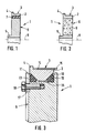
- the hub of the saw band roller is marked with the reference number 5.
- the metallic connection 6 between the hub 5 and the outer circumferential ring 2 or the running surface 3 is interrupted by a layer 7 of noise-damping material, in particular hard rubber, silicone or the like, which extends over the circumference. It is at this point mentions that more than one intermediate layer 7 can be provided between the tread 3 and the hub 5.
- the geometric axis of the saw band roller 1 is identified by the reference number 8.
- the tread ring 2 consists of a wear-resistant material, preferably steel, ceramic or the like.
- the hub 5 and connection 6 can be made of less wear-resistant, preferably also metallic material.
- the embodiment according to FIG. 2 differs from that according to FIG. 1 in that the entire connection between the tread ring 2 and the hub 5 is filled with a noise-damping material 9, preferably with polymer concrete.
- the tread 3 is formed by the outer circumferential surface of a race 2 with an approximately trapezoidal cross section, which by two on the two inclined surfaces 10, 11 adjacent rubber or the like rings 12, 13 on the wheel body or on the metallic connection 6 between the tread ring 2 and not shown hub is supported.
- the tread ring 2 shown in FIG. 3 also has a thrust collar 4 for the band saw blade identified by the reference number 14.
- the cutting teeth of the band saw blade 14 are indicated with the reference number 15.
- the tread ring 2 according to FIG. 3 is supported both radially and axially via the rubber rings 12, 13 within a circumferential groove formed on the wheel body or on the wheel disc 6, the one lateral limitation, left limitation in FIG. 3, of the circumferential groove 16 a holding ring 17 screwed to the wheel disk 6.
- the screw connection between the retaining ring 17 and the wheel disk 6 is indicated in FIG. 3 with the fastening screw 18.
- the rubber or the like rings 12, 13 are in the assembled State in the two corners of the circumferential groove 16. O-rings are preferably used for this, the cross-section of which, in the assembled state, deforms approximately triangularly in accordance with FIG. 3.
- the saw band roll 1 can also be manufactured in a sandwich construction and have at least one elastically flexible, in particular visco-elastic (silicone) intermediate layer, which extends transversely to the central axis 8 of the saw band roll 1.
- This embodiment is not shown in the drawing.
- the saw band roll according to the invention is also suitable for vertical band saws.
Landscapes
- Engineering & Computer Science (AREA)
- Mechanical Engineering (AREA)
- Sawing (AREA)
- Processing Of Stones Or Stones Resemblance Materials (AREA)
- Polishing Bodies And Polishing Tools (AREA)
Description
- Die Erfindung betrifft eine Sägebandrolle, insbesondere für Horizontal-Bandsägemaschinen, deren das Sägeband tragende Umfangs- bzw. Lauffläche aus einem verschleißfesten, harten, metallischen Werkstoff besteht, wobei zwischen der Lauffläche und der Habe der Sägebandrolle geräusch- und vibrationsdämpfendes Material angeordnet ist.
- Es ist allgemein bekannt, daß bei Bandsägemaschinen das Bandsägeblatt beim Umlauf um die Sägebandrollen, insbesondere beim Schneidvorgang, ein schrilles und kreischendes Geräusch hervorruft, wobei der Grund dafür primär darin liegt, daß das Sägeband während des Schneidvorganges in Quer- und in Längsrichtung in Schwingungen gerät. Außer den schrillen und kreischenden Geräuschen, die für das Umfeld sehr störend sind, haben die Vibrationen des Bandsägeblatts auch einen schädlichen Einfluß auf die Schneidgenauigkeit und die Schneidleistung sowie auf die Lebensdauer des Bandsägeblatts. Des weiteren wird das Schneidöl vom schwingenden Bandsägeblatt regelrecht verspritzt unter Ausbildung eines Schneidölnebels. Schließlich führen die Vibrationen des Bandsägeblatts zu einer rauhen Schnittfläche am geschnittenen Werkstück und zu einem Schneidspalt, der am Anfang des Schnittes breiter ist als der sich später entwikkelnde und durch die Geometrie des Sägeblatts vorgegebene Schneidspalt. Bei stärkeren Vibrationen läßt sich ein genauer, gerader Schnitt nicht mehr erreichen.
- Zur Lösung der genannten Probleme wird zum einen vorgeschlagen, die Lauffläche der Sägebandrolle mit einem profilierten Belag aus elastischem Material zu versehen (US-A 33 63 495), wobei nach der DE-C 27 40 212 der Laufflächenbelag durch O-Ringe gebildet wird, die in seitlichem Abstand voneinander in schwalbenschwanzförmigen Umfangsnoten der Sägebandrolle liegen. Diese Konstruktion hat jedoch den Nachteil, daß sie extrem verschleißanfällig ist, so daß nach kürzester Betriebszeit der profilierte Belag aus elastischem Material ausgetauscht werden muß.
- Zum anderen wurde zur Lösung des vorgenannten Problems vorgeschlagen, bei einer nach Art eines Speichenrades ausgebildeten Sägebandrolle die Zwischenräume zwischen den Speichen einerseits und dem Laufkranz und der Habe andererseits mit Polymerbeton auszufüllen (Bandsägemaschine PBA 1660/1660 der Firma KASTO Karl Stolzer; Hinweis z.B. in VDI - Z. Bd. 129 (1987) Nr. 1 - Januar, S. 81). Dadurch wird zwar eine gewisse Geräusch- und Vibrationsdämpfung erzielt, ohne daß die vorerwähnten Verschleißprobleme auftreten, andererseits läßt auch diese Konstruktion bezüglich der Geräusch- und Vibrationsdämpfung durchaus noch zu wünschen übrig, insbesondere im Hinblick darauf, daß die Speichen jeweils als Hohlkastenprofile ausgebildet sind.
- Auch in der US-A-3 968 715 werden geräuschdämpfende Maßnahmen an einer Sägebandrolle vorgeschlagen derart, daß das Sägeband auf einem metallischen Ring abgestützt ist, der über eine elastische Zwischenschicht auf einer äußeren Umfangsfläche der Sägebandrolle gelagert ist. Der metallische Ring wird seitlich gehalten durch einen Sägeband-Anlaufbund einerseits und Haltelaschen andererseits. Dementsprechend ist eine metallische Berührung zwischen dem genannten metallischen Ring und der Sägebandrolle bzw. deren Habe nicht ausgeschlossen. Insbesondere liegt bei der bekannten Konstruktion das Sägeband unmittelbar am mit der Nabe der Sägebandrolle einheitlich verbundenen Anlaufbund an (Sp.6, Z. 61-67 der US-A-3 968 715). Dementsprechend ist auch hier eine metallische Geräuschbrücke zwischen Sägeband und Habe der Sägebandrolle vorhanden.
- Der vorliegenden Erfindung liegt die Aufgabe zugrunde, die genannten Nachteile der bekannten Konstruktionen zu vermeiden und eine Sägebandrolle so auszubilden, daß bei unverändert hoher Verschleißfestigkeit ein äußerst geräuscharmer und zugleich präziser Lauf des Sägebandes erreicht wird.
- Diese Aufgabe wird durch die kennzeichnenden Merkmale des Patentanspruchs 1 gelöst, wobei die Unteransprüche bevorzugte konstruktive Details der Erfindung betreffen.
- Die Bedeutung der Erfindung liegt also darin, daß zwischen der Lauffläche der Sägebandrolle, die aus Verschleißgründen aus Werkstoff mit harter Oberfläche gebildet ist, und der Nabe der Sägebandrolle die metallische Verbindung unterbrochen wird, und zwar mittels eines geäuschdämpfenden Materials. Durch Verwendung der vorgeschlagenen Materialien wird die Festigkeit bzw. Stabilität der Sägebandrolle nicht beeinträchtigt. Gleichzeitig wird jedoch eine hohe Geräusch- und Vibrationsdämpfung erreicht.
- Eine besonders vorteilhafte konstruktive Ausführungsform ist in den Ansprüchen 2 und 4 beschrieben, die sich sowohl durch eine hohe Geräusch- und Vibrationsdämpfung als auch hohe Rundlaufgenauigkeit auszeichnet, so daß eine höhere Vorspannung des Bandsägeblatts möglich ist.
- Zusätzlich, aber auch unabhängig davon, können zur Geräusch-und Vibrationsdämpfung auch noch die Maßnahmen nach Anspruch 4 dienen. Dementsprechend erstreckt sich das geräuschdämpfende Material nicht ringförmig um die Achse der Sägebandrolle, sondern quer dazu.
- Nachstehend werden drei Ausführungsformen einer erfindungsgemäß ausgebildeten Sägebandrolle anhand der beigefügten Zeichnung näher erläutert. Es zeigen:
- Fig. 1
- eine erste Ausführungsform einer erfindungsgemäß ausgebildeten Sägebandrolle im schematischen Teilschnitt;
- Fig. 2
- eine zweite Ausführungsform einer erfindungsgemäß ausgebildeten Sägebandrolle im schematischen Teilschnitt; und
- Fig. 3
- eine dritte Ausführungsform einer erfindungsgemäß ausgebildeten Sägebandrolle im schematischen Teilschnitt.
- Die im Teilschnitt dargestellte Sägebandrolle 1 gemäß Fig. 1 besteht aus einem äußeren Ring 2, dessen Umfangsfläche 3 die Lauffläche für das nichtdargestellte Bandsägeblatt darstellt. An einer Seite, nämlich der in Fig. 1 linken Seite, ist die Lauffläche 3 durch einen Anlaufbund 4 begrenzt. Die Nabe der Sägebandrolle ist mit der Bezugsziffer 5 gekennzeichnet. Die metallische Verbindung 6 zwischen der Nabe 5 und dem äußeren Umfangsring 2 bzw. der Lauffläche 3 ist durch eine sich über den Umfang erstreckende Schicht 7 aus geräuschdämpfendem Material, insbesondere Hartgummi, Silikon oder dergleichen unterbrochen. Es sei an dieser Stelle erwähnt, daß mehr als eine Zwischenschicht 7 zwischen Lauffläche 3 und Nabe 5 vorgesehen sein können. Die geometrische Achse der Sägebandrolle 1 ist durch die Bezugsziffer 8 gekennzeichnet. Wie eingangs bereits ausgeführt, besteht der Laufflächenring 2 aus einem verschleißfesten Material, vorzugsweise Stahl, Keramik oder dergl. Die Nabe 5 sowie Verbindung 6 können aus weniger verschleißfestem, vorzugsweise ebenfalls metallischem Werkstoff hergestellt sein.
- Die Ausführungsform nach Fig. 2 unterscheidet sich von derjenigen nach Fig. 1 dadurch, daß die gesamte Verbindung zwischen dem Laufflächenring 2 und der Nabe 5 durch ein geräuschdämpfendes Material 9 ausgefüllt ist, und zwar vorzugsweise durch Polymer-Beton.
- Bei der Ausführungsform nach Fig. 3 wird die Lauffläche 3 durch die äußere Umfangsfläche eines Laufrings 2 mit etwa trapezförmigem Querschnitt gebildet, der durch zwei an den beiden Schrägflächen 10, 11 anliegende Gummi- oder dergleichen -ringe 12, 13 am Radkörper bzw. an der metallischen Verbindung 6 zwischen Laufflächenring 2 und nichtdargestellter Nabe abgestützt ist. Auch der in Fig. 3 dargestellte Laufflächenring 2 weist einen Anlaufbund 4 für das mit der Bezugsziffer 14 gekennzeichnete Bandsägeblatt auf. Die Schneidzähne des Bandsägeblatts 14 sind mit der Bezugsziffer 15 angedeutet.
- Der Laufflächenring 2 gemäß Fig. 3 ist innerhalb einer am Radkörper bzw. an der Radscheibe 6 ausgebildeten Umfangsnut sowohl radial als auch axial über die Gummiringe 12, 13 abgestützt, wobei die eine seitliche Begrenzung, in Fig. 3 linke Begrenzung, der Umfangsnut 16 durch einen mit der Radscheibe 6 verschraubten Haltering 17 erfolgt. Die Schraubverbindung zwischen Haltering 17 und Radscheibe 6 ist in Fig. 3 mit der Befestigungsschraube 18 angedeutet. Die Gummi- oder dergleichen -ringe 12, 13 liegen im montierten Zustand in den beiden Ecken der Umfangsnut 16. Vorzugsweise werden dafür O-Ringe verwendet, deren Querschnitt sich im montierten Zustand entsprechend Fig. 3 etwa dreieckförmig verformt.
- Wie oben ausgeführt, kann die Sägebandrolle 1 auch in Sandwichbauweise hergestellt sein und mindestens eine elastisch nachgiebige, insbesondere visko-elastische (Silikon) Zwischenschicht aufweisen, die sich quer zur Mittelachse 8 der Sägebandrolle 1 erstreckt. Diese Ausführungsform ist zeichnerisch nicht dargestellt.
- Desweiteren ist die erfindungsgemäße Sägebandrolle auch für Vertikalbandsägen geeignet.
Claims (4)
- Sägebandrolle, insbesondere für Horizontal-Bandsägemaschinen, deren das Sägeband tragende Umfangs- bzw. Lauffläche aus einem verschleißfesten, harten, metallischen Werkstoff besteht, wobei zwischen der Lauffläche und der Nabe der Sägebandrolle geräusch- und vibrationsdämpfendes Material angeordnet ist,
dadurch gekennzeichnet, daß
die metallische Verbindung (6) zwischen Lauffläche (3) und Nabe (5) der Sägebandrolle (1) durch mindestens eine Zwischenschicht (7; 12, 13) aus geräusch- und vibrationsdämpfendem Material vollständig unterbrochen ist, wobei als geräusch- und vibrationsdämpfendes Material Gummi, insbesondere Hartgummi, Silikon oder dgl. Elastomermaterial dient. - Sägebandrolle nach Anspruch 1,
dadurch gekennzeichnet, daß die geräusch- und vibrationsdämpfende Zwischenschicht durch elastische Bänder, insbesondere Gummi- oder dgl. -ringe (12, 13) gebildet ist, die die Lauffläche (3) an der die metallische Verbindung (6) zwischen Lauffläche (3) und Nabe (5) definierenden Radscheibe abstützen. - Sägebandrolle, nach Anspruch 1 oder 2,
dadurch gekennzeichnet, daß sie in Sandwich-Bauweise hergestellt ist und mindestens eine sich quer zur Mittelachse (8) erstreckende elastisch nachgiebige, insbesondere visko-elastische Zwischenschicht aufweist. - Sägebandrolle nach Anspruch 2,
dadurch gekennzeichnet, daß die Lauffläche (3) durch die äußere Umfangsfläche eines Laufrings (2) mit etwa trapezförmigem Querschnitt gebildet ist, der durch zwei an den beiden Schrägflächen (10, 11) anliegende Gummi- oder dgl. -ringe (12, 13) gegenüber der die Verbindung (6) zwischen Lauffläche (3) und Habe (5) bildenden Radscheibe abgestützt ist.
Applications Claiming Priority (2)
| Application Number | Priority Date | Filing Date | Title |
|---|---|---|---|
| DE3819018 | 1988-06-03 | ||
| DE3819018A DE3819018C1 (de) | 1988-06-03 | 1988-06-03 |
Publications (2)
| Publication Number | Publication Date |
|---|---|
| EP0344358A1 EP0344358A1 (de) | 1989-12-06 |
| EP0344358B1 true EP0344358B1 (de) | 1993-01-07 |
Family
ID=6355838
Family Applications (1)
| Application Number | Title | Priority Date | Filing Date |
|---|---|---|---|
| EP88116593A Expired - Lifetime EP0344358B1 (de) | 1988-06-03 | 1988-10-06 | Sägebandrolle |
Country Status (5)
| Country | Link |
|---|---|
| US (1) | US4981062A (de) |
| EP (1) | EP0344358B1 (de) |
| JP (1) | JPH0224021A (de) |
| CA (1) | CA1317199C (de) |
| DE (2) | DE3819018C1 (de) |
Families Citing this family (5)
| Publication number | Priority date | Publication date | Assignee | Title |
|---|---|---|---|---|
| JP2574319Y2 (ja) * | 1992-02-20 | 1998-06-11 | 京セラ株式会社 | バンドソーガイド |
| KR100704868B1 (ko) | 2003-11-06 | 2007-04-09 | 가부시키가이샤 아마다 | 띠톱 기계 및 띠톱 기계에 있어서의 톱날 장착 방법, 톱날구동 방법 및 절단 가공 방법 |
| DE102004028484A1 (de) * | 2004-06-11 | 2005-12-29 | Ina-Schaeffler Kg | Reibradantrieb |
| US7520202B2 (en) * | 2006-11-09 | 2009-04-21 | Oav Equipment & Tools, Inc. | Guiding device for saw blade of band saw |
| DE102019124749A1 (de) * | 2019-09-13 | 2021-03-18 | Robert Röntgen GmbH & Co. KG | Bandsägemaschine |
Family Cites Families (17)
| Publication number | Priority date | Publication date | Assignee | Title |
|---|---|---|---|---|
| GB191000530A (de) * | 1900-01-01 | |||
| GB190000487A (en) * | 1900-01-09 | 1900-10-27 | James William King | Improvements in Band Saw Mechanism. |
| US918248A (en) * | 1908-03-09 | 1909-04-13 | Olmedo Cortez Wysong | Band-pulley. |
| US1916903A (en) * | 1932-04-18 | 1933-07-04 | Wine Albert | Safety band saw |
| US2701971A (en) * | 1950-04-01 | 1955-02-15 | Carter Andrew Gray | Wheel assembly |
| GB731246A (en) * | 1950-11-18 | 1955-06-08 | Midland Saw And Tool Company L | Improvements in or relating to band saws or like machines |
| US2954061A (en) * | 1958-07-14 | 1960-09-27 | Continental Machines | Drive wheel for band saws |
| US3257860A (en) * | 1964-06-01 | 1966-06-28 | Burroughs Corp | Vibration and shock insulating sprocket |
| US3363495A (en) * | 1966-01-19 | 1968-01-16 | Continental Machines | Drive wheel for band saws |
| US3483783A (en) * | 1968-01-30 | 1969-12-16 | Continental Machines | Vibration inhibiting means for band saws |
| US3935780A (en) * | 1975-02-24 | 1976-02-03 | Hoffmann John A | Band saw drive arrangement |
| US3968715A (en) * | 1975-06-27 | 1976-07-13 | Continental Machines, Inc. | Vibration resistant band saw wheel |
| US4002081A (en) * | 1976-01-12 | 1977-01-11 | Nagel-Chase Manufacturing Company | Pulley construction |
| US4027568A (en) * | 1976-05-24 | 1977-06-07 | Continental Machines, Inc. | Replaceable surface band wheel |
| JPS5333492A (en) * | 1976-09-08 | 1978-03-29 | Amada Co Ltd | Horizontal band sawing machine |
| JPS5852767B2 (ja) * | 1979-10-31 | 1983-11-25 | 株式会社 アマダ | 帯鋸盤における振動,騒音防止方法及び装置 |
| IT1180682B (it) * | 1983-04-26 | 1987-09-23 | Keuro Maschinenbau Gmbh | Macchina segatrice a nastro |
-
1988
- 1988-06-03 DE DE3819018A patent/DE3819018C1/de not_active Expired
- 1988-10-06 DE DE8888116593T patent/DE3877353D1/de not_active Expired - Lifetime
- 1988-10-06 EP EP88116593A patent/EP0344358B1/de not_active Expired - Lifetime
- 1988-12-01 CA CA000584770A patent/CA1317199C/en not_active Expired - Fee Related
-
1989
- 1989-05-25 US US07/357,079 patent/US4981062A/en not_active Expired - Fee Related
- 1989-05-30 JP JP1138996A patent/JPH0224021A/ja active Pending
Also Published As
| Publication number | Publication date |
|---|---|
| DE3877353D1 (de) | 1993-02-18 |
| EP0344358A1 (de) | 1989-12-06 |
| JPH0224021A (ja) | 1990-01-26 |
| US4981062A (en) | 1991-01-01 |
| CA1317199C (en) | 1993-05-04 |
| DE3819018C1 (de) | 1989-07-13 |
Similar Documents
| Publication | Publication Date | Title |
|---|---|---|
| EP0111125B1 (de) | Wälzlager für Radialbewegungen | |
| DE69903238T2 (de) | Diamantbeschichtetes kreissägeblatt | |
| EP1049565B1 (de) | Spanneinrichtung für schleifscheiben | |
| DE3444618A1 (de) | Radlager | |
| DE69016707T2 (de) | Dynamischer Dämpfer. | |
| DE102015221714A1 (de) | Verfahren und Vorrichtung zur Herstellung nicht zylindrischer Bohrungen mit mindestens einer Aussparung durch Honen | |
| WO2007051453A2 (de) | Radnabe mit zwischen den löchern für radschrauben ausgebildeten axialen ausnehmungen | |
| CH630010A5 (de) | Schienenrad mit resonanzabsorbern. | |
| DE102019114276B4 (de) | Profilierte Mutter eines Gewindetriebes, insbesondere Kugelgewindemutter eines Kugelgewindetriebes und Verfahren zu deren Herstellung | |
| EP1867420B1 (de) | Sägeblatt mit Seitenschlag | |
| DE3819018C1 (de) | ||
| WO2010028633A1 (de) | MEHRREIHIGES GROSSWÄLZLAGER MIT MEHRTEILIGEM AUßENRING | |
| CH665988A5 (de) | Schleifkoerper und schleifkoerperaufnahme insbesondere fuer eine zahnflankenschleifmaschine. | |
| EP2199632A1 (de) | Lagerelement mit porösen Elementen in Ringsegmenten | |
| DE102005012602B3 (de) | Verfahren zur Herstellung einer Lageranordnung | |
| EP0489092B1 (de) | Abrichten von schleifscheiben | |
| DE763225C (de) | Rollenlager | |
| EP0043136B1 (de) | Segmentierte Trennscheibe | |
| DE2720333C3 (de) | Schwingungsgedämpftes Schienenrad | |
| DE3310247A1 (de) | Schneidwerkzeug, insbesondere kreissaegenblatt | |
| DE2750743C3 (de) | Schwingungsgedämpftes Schienenrad | |
| DE3304397C2 (de) | ||
| EP2030715A1 (de) | Kreissägeblatt | |
| CH659217A5 (de) | Gummigefedertes schienenrad. | |
| DE102019100999A1 (de) | Lageranordnung zur angestellten Stützlagerung einer Welle mit einer Distanzringscheibe zur Einstellung des axialen Wellenspiels |
Legal Events
| Date | Code | Title | Description |
|---|---|---|---|
| PUAI | Public reference made under article 153(3) epc to a published international application that has entered the european phase |
Free format text: ORIGINAL CODE: 0009012 |
|
| AK | Designated contracting states |
Kind code of ref document: A1 Designated state(s): CH DE FR GB IT LI |
|
| 17P | Request for examination filed |
Effective date: 19900509 |
|
| 17Q | First examination report despatched |
Effective date: 19910422 |
|
| ITF | It: translation for a ep patent filed | ||
| GRAA | (expected) grant |
Free format text: ORIGINAL CODE: 0009210 |
|
| AK | Designated contracting states |
Kind code of ref document: B1 Designated state(s): CH DE FR GB IT LI |
|
| ET | Fr: translation filed | ||
| REF | Corresponds to: |
Ref document number: 3877353 Country of ref document: DE Date of ref document: 19930218 |
|
| GBT | Gb: translation of ep patent filed (gb section 77(6)(a)/1977) |
Effective date: 19930330 |
|
| PLBI | Opposition filed |
Free format text: ORIGINAL CODE: 0009260 |
|
| PLAB | Opposition data, opponent's data or that of the opponent's representative modified |
Free format text: ORIGINAL CODE: 0009299OPPO |
|
| 26 | Opposition filed |
Opponent name: KEURO BESITZ GMBH & CO EDV DIENSTLEISTUNGS KG Effective date: 19930922 |
|
| R26 | Opposition filed (corrected) |
Opponent name: KEURO BESITZ GMBH & CO EDV DIENSTLEISTUNGS KG Effective date: 19930922 |
|
| PLBM | Termination of opposition procedure: date of legal effect published |
Free format text: ORIGINAL CODE: 0009276 |
|
| STAA | Information on the status of an ep patent application or granted ep patent |
Free format text: STATUS: OPPOSITION PROCEDURE CLOSED |
|
| 27C | Opposition proceedings terminated |
Effective date: 19950703 |
|
| REG | Reference to a national code |
Ref country code: CH Ref legal event code: PUE Owner name: GUSTAV WAGNER MASCHINENFABRIK GMBH & CO. KG -DANN |
|
| REG | Reference to a national code |
Ref country code: GB Ref legal event code: 732E |
|
| REG | Reference to a national code |
Ref country code: FR Ref legal event code: TP Free format text: PUBLIE A TORT DANS LE BOPI 98/03 SUIVANT LA NOTIFICATION DANS LE BOPI 98/07 Ref country code: FR Ref legal event code: CA Free format text: PUBLIE A TORT DANS LE BOPI 98/03 SUIVANT LA NOTIFICATION DANS LE BOPI 98/07 |
|
| REG | Reference to a national code |
Ref country code: FR Ref legal event code: TP Ref country code: FR Ref legal event code: CA |
|
| REG | Reference to a national code |
Ref country code: CH Ref legal event code: PUE Owner name: WAGNER BANDSAEGEN PRODUKTIONS GMBH TRANSFER- KEURO |
|
| REG | Reference to a national code |
Ref country code: FR Ref legal event code: TP |
|
| REG | Reference to a national code |
Ref country code: GB Ref legal event code: 732E |
|
| REG | Reference to a national code |
Ref country code: GB Ref legal event code: IF02 |
|
| PGFP | Annual fee paid to national office [announced via postgrant information from national office to epo] |
Ref country code: CH Payment date: 20021230 Year of fee payment: 15 |
|
| PG25 | Lapsed in a contracting state [announced via postgrant information from national office to epo] |
Ref country code: CH Free format text: LAPSE BECAUSE OF NON-PAYMENT OF DUE FEES Effective date: 20031031 Ref country code: LI Free format text: LAPSE BECAUSE OF NON-PAYMENT OF DUE FEES Effective date: 20031031 |
|
| REG | Reference to a national code |
Ref country code: CH Ref legal event code: PL |
|
| PGFP | Annual fee paid to national office [announced via postgrant information from national office to epo] |
Ref country code: IT Payment date: 20071010 Year of fee payment: 20 |
|
| PGFP | Annual fee paid to national office [announced via postgrant information from national office to epo] |
Ref country code: FR Payment date: 20071029 Year of fee payment: 20 Ref country code: GB Payment date: 20071031 Year of fee payment: 20 |
|
| PGFP | Annual fee paid to national office [announced via postgrant information from national office to epo] |
Ref country code: DE Payment date: 20071219 Year of fee payment: 20 |
|
| REG | Reference to a national code |
Ref country code: GB Ref legal event code: PE20 Expiry date: 20081005 |
|
| PG25 | Lapsed in a contracting state [announced via postgrant information from national office to epo] |
Ref country code: GB Free format text: LAPSE BECAUSE OF EXPIRATION OF PROTECTION Effective date: 20081005 |