EP0344094B1 - Réservoir de détente pour fluides chauds sous pression - Google Patents
Réservoir de détente pour fluides chauds sous pression Download PDFInfo
- Publication number
- EP0344094B1 EP0344094B1 EP89730114A EP89730114A EP0344094B1 EP 0344094 B1 EP0344094 B1 EP 0344094B1 EP 89730114 A EP89730114 A EP 89730114A EP 89730114 A EP89730114 A EP 89730114A EP 0344094 B1 EP0344094 B1 EP 0344094B1
- Authority
- EP
- European Patent Office
- Prior art keywords
- flash
- chambers
- pressure
- condensate
- chamber
- Prior art date
- Legal status (The legal status is an assumption and is not a legal conclusion. Google has not performed a legal analysis and makes no representation as to the accuracy of the status listed.)
- Expired - Lifetime
Links
- 239000012530 fluid Substances 0.000 title claims 5
- XLYOFNOQVPJJNP-UHFFFAOYSA-N water Substances O XLYOFNOQVPJJNP-UHFFFAOYSA-N 0.000 claims abstract description 18
- 238000001816 cooling Methods 0.000 claims description 5
- 239000002699 waste material Substances 0.000 claims description 3
- 238000000638 solvent extraction Methods 0.000 claims 4
- 239000007788 liquid Substances 0.000 abstract description 5
- 238000005192 partition Methods 0.000 abstract description 5
- 238000000034 method Methods 0.000 description 8
- 238000001704 evaporation Methods 0.000 description 7
- 230000008020 evaporation Effects 0.000 description 7
- 239000002826 coolant Substances 0.000 description 3
- 239000012071 phase Substances 0.000 description 3
- 238000011161 development Methods 0.000 description 2
- 230000018109 developmental process Effects 0.000 description 2
- 238000010438 heat treatment Methods 0.000 description 2
- 238000011084 recovery Methods 0.000 description 2
- 238000000926 separation method Methods 0.000 description 2
- 230000005494 condensation Effects 0.000 description 1
- 238000009833 condensation Methods 0.000 description 1
- 230000006735 deficit Effects 0.000 description 1
- 238000007872 degassing Methods 0.000 description 1
- 239000007791 liquid phase Substances 0.000 description 1
- 239000007921 spray Substances 0.000 description 1
Images


Classifications
-
- F—MECHANICAL ENGINEERING; LIGHTING; HEATING; WEAPONS; BLASTING
- F22—STEAM GENERATION
- F22B—METHODS OF STEAM GENERATION; STEAM BOILERS
- F22B3/00—Other methods of steam generation; Steam boilers not provided for in other groups of this subclass
- F22B3/04—Other methods of steam generation; Steam boilers not provided for in other groups of this subclass by drop in pressure of high-pressure hot water within pressure-reducing chambers, e.g. in accumulators
-
- F—MECHANICAL ENGINEERING; LIGHTING; HEATING; WEAPONS; BLASTING
- F22—STEAM GENERATION
- F22B—METHODS OF STEAM GENERATION; STEAM BOILERS
- F22B37/00—Component parts or details of steam boilers
- F22B37/02—Component parts or details of steam boilers applicable to more than one kind or type of steam boiler
- F22B37/42—Applications, arrangements or dispositions of alarm or automatic safety devices
-
- F—MECHANICAL ENGINEERING; LIGHTING; HEATING; WEAPONS; BLASTING
- F22—STEAM GENERATION
- F22B—METHODS OF STEAM GENERATION; STEAM BOILERS
- F22B37/00—Component parts or details of steam boilers
- F22B37/02—Component parts or details of steam boilers applicable to more than one kind or type of steam boiler
- F22B37/48—Devices or arrangements for removing water, minerals or sludge from boilers ; Arrangement of cleaning apparatus in boilers; Combinations thereof with boilers
- F22B37/54—De-sludging or blow-down devices
-
- F—MECHANICAL ENGINEERING; LIGHTING; HEATING; WEAPONS; BLASTING
- F22—STEAM GENERATION
- F22D—PREHEATING, OR ACCUMULATING PREHEATED, FEED-WATER FOR STEAM GENERATION; FEED-WATER SUPPLY FOR STEAM GENERATION; CONTROLLING WATER LEVEL FOR STEAM GENERATION; AUXILIARY DEVICES FOR PROMOTING WATER CIRCULATION WITHIN STEAM BOILERS
- F22D1/00—Feed-water heaters, i.e. economisers or like preheaters
- F22D1/32—Feed-water heaters, i.e. economisers or like preheaters arranged to be heated by steam, e.g. bled from turbines
Definitions
- the invention relates to a relaxation device for pressurized hot media, in particular water, according to the preamble of claim 1.
- lances which are to be regarded as horizontal manifolds.
- a lance which can have a considerable length, usually opens tangentially into the expansion tank.
- the individual drains that are opened to the lance via drain valves can lead to hot water with very different pressure levels.
- evaporation occurs immediately behind the drain valve, with a 2-phase flow (steam / water) forming in the lance.
- the object of the invention is to provide a relaxation device of the generic type which largely avoids these disadvantages.
- the basic idea of the invention is to be seen in the fact that a consequent separation of processes of different pressure levels is carried out insofar as a hot medium under pressure with its liquid phase is kept completely separate from liquid media of other pressure levels during the expansion to approximately ambient pressure. This is achieved in that the media streams are introduced into the expansion device in separate lines, the drain valves being arranged close to the expansion device.
- the relaxation of the media and the associated steam generation (evaporation) takes place in separate relaxation chambers, which are partitioned off from each other by partitions. Only media flows of the same pressure level can be introduced into a common expansion chamber. The expediency of such a joint treatment depends in particular on whether the throughput of the relaxation chamber is adequate for the flow rates to be expected if necessary.
- the amounts of steam generated during the degassing in the individual expansion chambers immediately pass into a common, large-volume steam collection space, since the expansion chambers are open at the top.
- the steam can be discharged almost without pressure from the steam collecting space via an exhaust steam line. It is also possible to arrange a heat exchanger in the steam collecting space in order to largely recover the heat energy present in the steam and the liquid medium (eg processed process water) through condensation of the steam.
- the relaxed liquid medium in the relaxation chamber can flow calmly through a perforated floor into an underlying condensate collecting space, which is common to all relaxation chambers.
- the condensate level is e.g. always kept at the same level via a process loop or other control device. So that the evaporation still taking place in the condensate collection space does not lead to faults, a pressure compensation line is provided to the steam collection space.
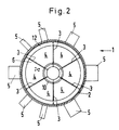
- the expansion device 1 shown in FIGS. 1 and 2 has a standing, essentially circular-cylindrical housing 2, which is closed by a base through which a condensate drain 8 is guided and by a cover through which an evaporation line 11 is guided.
- a base through which a condensate drain 8 is guided and by a cover through which an evaporation line 11 is guided.
- other housing shapes eg with a polygonal cross section
- numerous radially arranged supply lines 5 open, through which, for example, hot pressurized water can be introduced into the expansion device 1. In Figure 1, only one of these leads 5 is shown.
- the drain valves (not shown) for opening and closing these supply lines 5 can be attached in the immediate vicinity of the housing shell 2.
- Each feed line 5 leads into an expansion chamber 4, which is formed in each case between a part of the housing shell 2, two lateral vertical, radially oriented partition walls 3 and a part of a pressure compensation line 10 arranged coaxially to the housing 2.
- the individual expansion chambers 4 are arranged as sectors around the central pressure compensation line 10. At the bottom, they are closed off by a common perforated base 6 welded to the housing jacket 2, under which the condensate collecting space 7 reaching to the bottom of the housing 2 is located. At the top, all of the relaxation chambers 4 are open to a common steam collecting space 9.
- Two expansion chambers 4 each have two feed lines 5 of smaller diameter, which are provided for media flows of the same pressure level, while all the others have only a single feed line 5.
- the dividing walls 4 are welded only to the perforated base 6 and the pressure compensation line 10, which is designed as a conically expanding tube, but not along the contact surface line with the housing 2.
- each partial flow can relax completely independently and undisturbed from the others. Since the shut-off elements of the feed lines 5 are arranged close to the housing 2, there are no disturbing evaporation and 2-phase flows in the feed lines 5.
- the pressure water flowing radially into the expansion chamber 4 flows against the central pressure compensation tube 10 and the radially converging partition walls 3.
- the conical expansion of the pressure compensation tube 10 helps to ensure that the pressure water is not thrown upwards into the steam collection chamber 9, if possible, but rather into the expansion chamber 4 is thrown back.
- the holding strip 12, which impedes the free access of the hot spray water into the steam collecting space 9, can also make a contribution in this sense.
- the steam which is produced in the expansion chamber 4 and has an ambient pressure can reach the large-volume steam collecting space 9 almost unhindered and can be discharged from there through the exhaust steam line 11.
- the relaxed hot water can flow through the perforated base 6 into the condensate collecting space 7, where a constant condensate level is maintained, for example, by a siphon-like drain.
- the steam that subsequently arises in the condensate collection space 7 can flow unhindered into the steam collection space 9 via the central pressure compensation tube 10.
- a heat exchanger 13 can be introduced into the condensate collecting space 9.
- This heat exchanger 13 has a cylindrical inner jacket 14 designed as a perforated jacket, through which the steam can flow into an annular cooling chamber through which heat exchanger tubes 15 pass.
- the cooling space is closed peripherally by a tight outer jacket 16 and at the top by the disk-shaped distribution channels of the coolant supply line 19 and the coolant discharge line 20.
- the cooling space is delimited by a bottom 17 which is tightly connected to the housing jacket 2 and which is pulled upwards and directly adjoins the perforated jacket 14.
- the condensate formed by the cooling can collect above the bottom 17.
- the condensate level is always held at approximately the same level by a holding device, not shown, which is connected to the condensate drain line 18. Since the outer jacket 16 is immersed in the condensate, the steam collecting space 9 is itself sealed off from the outside, so that practically complete recovery of the process water is possible as long as the coolant supply is sufficient.
- the condensate level is pressed down as a result of the pressure increase in the steam collection chamber 9 until the excess steam passes past the lower edge of the outer jacket 16 through the annular space between the outer jacket 16 and the housing jacket 2 above in the evaporation chamber 21 and from there, for example can be derived into the atmosphere.
Landscapes
- Engineering & Computer Science (AREA)
- Physics & Mathematics (AREA)
- Thermal Sciences (AREA)
- Mechanical Engineering (AREA)
- General Engineering & Computer Science (AREA)
- Heat-Exchange Devices With Radiators And Conduit Assemblies (AREA)
- Yarns And Mechanical Finishing Of Yarns Or Ropes (AREA)
- Crucibles And Fluidized-Bed Furnaces (AREA)
- Crystals, And After-Treatments Of Crystals (AREA)
- Massaging Devices (AREA)
- Treatment Of Fiber Materials (AREA)
Claims (7)
Priority Applications (1)
| Application Number | Priority Date | Filing Date | Title |
|---|---|---|---|
| AT89730114T ATE71200T1 (de) | 1988-05-26 | 1989-05-02 | Entspannungsvorrichtung fuer unter druck stehende heisse flussigkeiten. |
Applications Claiming Priority (2)
| Application Number | Priority Date | Filing Date | Title |
|---|---|---|---|
| DE3818165 | 1988-05-26 | ||
| DE3818165A DE3818165C1 (fr) | 1988-05-26 | 1988-05-26 |
Publications (2)
| Publication Number | Publication Date |
|---|---|
| EP0344094A1 EP0344094A1 (fr) | 1989-11-29 |
| EP0344094B1 true EP0344094B1 (fr) | 1992-01-02 |
Family
ID=6355318
Family Applications (1)
| Application Number | Title | Priority Date | Filing Date |
|---|---|---|---|
| EP89730114A Expired - Lifetime EP0344094B1 (fr) | 1988-05-26 | 1989-05-02 | Réservoir de détente pour fluides chauds sous pression |
Country Status (5)
| Country | Link |
|---|---|
| EP (1) | EP0344094B1 (fr) |
| AT (1) | ATE71200T1 (fr) |
| DD (1) | DD283857A5 (fr) |
| DE (2) | DE3818165C1 (fr) |
| NO (1) | NO167414C (fr) |
Families Citing this family (5)
| Publication number | Priority date | Publication date | Assignee | Title |
|---|---|---|---|---|
| DE19881574D2 (de) * | 1997-08-28 | 2000-07-27 | Walter Georg Steiner | Erzeugung von elektrischem Strom und Wasserrückgewinnung aus der Atmosphäre mit Solar und Windenergie |
| CN104235824B (zh) * | 2014-09-25 | 2016-02-03 | 无锡纳润特科技有限公司 | 锅炉排污膨胀器的切向污水分散装置 |
| RU2655161C1 (ru) * | 2017-06-02 | 2018-05-24 | Акционерное общество Инжиниринговая компания "АСЭ" | Одноконтурная атомная электростанция с теплоносителем под давлением |
| CN110746024B (zh) * | 2019-10-28 | 2024-08-20 | 中国华电科工集团有限公司 | 一种低温省煤器废水浓缩余热回用装置 |
| CN110746025A (zh) * | 2019-10-28 | 2020-02-04 | 中国华电科工集团有限公司 | 一种低温负压废水零排放系统 |
Family Cites Families (3)
| Publication number | Priority date | Publication date | Assignee | Title |
|---|---|---|---|---|
| GB1579325A (en) * | 1977-05-30 | 1980-11-19 | Curwen & Newberry Ltd | Blowdown tanks for boller installations |
| JPS5755304A (en) * | 1980-09-22 | 1982-04-02 | Tokyo Shibaura Electric Co | Flasher |
| JPS6179905A (ja) * | 1984-09-28 | 1986-04-23 | 株式会社日立製作所 | ドレン回収システム |
-
1988
- 1988-05-26 DE DE3818165A patent/DE3818165C1/de not_active Expired
-
1989
- 1989-02-28 NO NO890843A patent/NO167414C/no unknown
- 1989-05-02 EP EP89730114A patent/EP0344094B1/fr not_active Expired - Lifetime
- 1989-05-02 AT AT89730114T patent/ATE71200T1/de not_active IP Right Cessation
- 1989-05-02 DE DE8989730114T patent/DE58900654D1/de not_active Expired - Fee Related
- 1989-05-22 DD DD89328798A patent/DD283857A5/de not_active IP Right Cessation
Also Published As
| Publication number | Publication date |
|---|---|
| EP0344094A1 (fr) | 1989-11-29 |
| NO167414C (no) | 1991-10-30 |
| DD283857A5 (de) | 1990-10-24 |
| NO890843L (no) | 1989-11-27 |
| DE58900654D1 (de) | 1992-02-13 |
| DE3818165C1 (fr) | 1989-12-28 |
| ATE71200T1 (de) | 1992-01-15 |
| NO890843D0 (no) | 1989-02-28 |
| NO167414B (no) | 1991-07-22 |
Similar Documents
| Publication | Publication Date | Title |
|---|---|---|
| DE102004007189A1 (de) | Verfahren zur Luftbehandlung in einem Fahrzeug und Vorrichtung hierfür | |
| DE3031454C2 (de) | Seitenstrom-Kondensationssystem | |
| DE1937821A1 (de) | Verbesserungen an Kaeltepumpanlagen von starker Leistung | |
| DE19930546C1 (de) | Dampfsterilisator | |
| EP0160161A1 (fr) | Echangeur de chaleur pour refroidir des gaz | |
| DE1948429A1 (de) | Feuchtigkeitsabscheider mit Nacherwaermung | |
| DE2109825B2 (de) | Dampferzeuger mit in einem vertikalen Druckbehälter angeordneten Rohrbündel | |
| EP0215230B1 (fr) | Dispositif de dégazage de condensat dans le circuit d'une unité de production d'électricité | |
| EP0344094B1 (fr) | Réservoir de détente pour fluides chauds sous pression | |
| DE2909647C2 (de) | Verfahren und Vorrichtung zur Reinigung von Gichtgas | |
| DE69318237T2 (de) | Kondensator für Dampfturbine und Verfahren zum Betieb desselben | |
| EP0265908A2 (fr) | Appareil pour l'ébullition du moût | |
| DE1426907A1 (de) | Dampfkraftanlage | |
| EP0807605B1 (fr) | Dispositif pour le dessalage et le traitement d'eau | |
| DE2400123C3 (de) | Verfahren und Vorrichtung zum Konzentrieren von flüssigen radioaktiven Abfällen | |
| DE3121297C2 (de) | Vorrichtung zum Regeln der Temperatur eines korrosiven Gases, insbesondere Synthesegas | |
| DE2019731C3 (de) | Verfahren zur Aufbereitung von Abwasserschlamm zur Verbesserung seiner Entwässerungseigenschaften und Vorrichtung zur Durchführung des Verfahrens | |
| DE3023094A1 (de) | Verfahren und vorrichtung zur dampferzeugung | |
| DE2414080C3 (de) | Flüssigkeitsfilter | |
| DE3834351C2 (fr) | ||
| DE2137437B2 (de) | Vorrichtung zum kompostieren von muell | |
| CH670696A5 (en) | Synthesis gas heat exchanger | |
| DE1124527B (de) | Waermetauschanordnung, insbesondere fuer Reaktoranlagen, mit in sich geschlossenem Kuehlmittelkreislauf | |
| DE2205587C3 (de) | Abgassystem für Kernreaktoren | |
| DE2523874C3 (de) | Dampferzeuger mit vertikalem Druckgefäss |
Legal Events
| Date | Code | Title | Description |
|---|---|---|---|
| PUAI | Public reference made under article 153(3) epc to a published international application that has entered the european phase |
Free format text: ORIGINAL CODE: 0009012 |
|
| AK | Designated contracting states |
Kind code of ref document: A1 Designated state(s): AT BE CH DE LI NL SE |
|
| 17P | Request for examination filed |
Effective date: 19891019 |
|
| 17Q | First examination report despatched |
Effective date: 19910225 |
|
| GRAA | (expected) grant |
Free format text: ORIGINAL CODE: 0009210 |
|
| AK | Designated contracting states |
Kind code of ref document: B1 Designated state(s): AT BE CH DE LI NL SE |
|
| REF | Corresponds to: |
Ref document number: 71200 Country of ref document: AT Date of ref document: 19920115 Kind code of ref document: T |
|
| REF | Corresponds to: |
Ref document number: 58900654 Country of ref document: DE Date of ref document: 19920213 |
|
| PLBE | No opposition filed within time limit |
Free format text: ORIGINAL CODE: 0009261 |
|
| STAA | Information on the status of an ep patent application or granted ep patent |
Free format text: STATUS: NO OPPOSITION FILED WITHIN TIME LIMIT |
|
| 26N | No opposition filed | ||
| EAL | Se: european patent in force in sweden |
Ref document number: 89730114.9 |
|
| PGFP | Annual fee paid to national office [announced via postgrant information from national office to epo] |
Ref country code: SE Payment date: 19990421 Year of fee payment: 11 Ref country code: CH Payment date: 19990421 Year of fee payment: 11 |
|
| PGFP | Annual fee paid to national office [announced via postgrant information from national office to epo] |
Ref country code: AT Payment date: 19990422 Year of fee payment: 11 |
|
| PGFP | Annual fee paid to national office [announced via postgrant information from national office to epo] |
Ref country code: BE Payment date: 19990426 Year of fee payment: 11 |
|
| PGFP | Annual fee paid to national office [announced via postgrant information from national office to epo] |
Ref country code: NL Payment date: 19990427 Year of fee payment: 11 |
|
| PGFP | Annual fee paid to national office [announced via postgrant information from national office to epo] |
Ref country code: DE Payment date: 19990621 Year of fee payment: 11 |
|
| PG25 | Lapsed in a contracting state [announced via postgrant information from national office to epo] |
Ref country code: AT Free format text: LAPSE BECAUSE OF NON-PAYMENT OF DUE FEES Effective date: 20000502 |
|
| PG25 | Lapsed in a contracting state [announced via postgrant information from national office to epo] |
Ref country code: SE Free format text: LAPSE BECAUSE OF NON-PAYMENT OF DUE FEES Effective date: 20000503 |
|
| PG25 | Lapsed in a contracting state [announced via postgrant information from national office to epo] |
Ref country code: LI Free format text: LAPSE BECAUSE OF NON-PAYMENT OF DUE FEES Effective date: 20000531 Ref country code: CH Free format text: LAPSE BECAUSE OF NON-PAYMENT OF DUE FEES Effective date: 20000531 Ref country code: BE Free format text: LAPSE BECAUSE OF NON-PAYMENT OF DUE FEES Effective date: 20000531 |
|
| BERE | Be: lapsed |
Owner name: MANNESMANN A.G. Effective date: 20000531 |
|
| PG25 | Lapsed in a contracting state [announced via postgrant information from national office to epo] |
Ref country code: NL Free format text: LAPSE BECAUSE OF NON-PAYMENT OF DUE FEES Effective date: 20001201 |
|
| REG | Reference to a national code |
Ref country code: CH Ref legal event code: PL |
|
| EUG | Se: european patent has lapsed |
Ref document number: 89730114.9 |
|
| NLV4 | Nl: lapsed or anulled due to non-payment of the annual fee |
Effective date: 20001201 |
|
| PG25 | Lapsed in a contracting state [announced via postgrant information from national office to epo] |
Ref country code: DE Free format text: LAPSE BECAUSE OF NON-PAYMENT OF DUE FEES Effective date: 20010301 |