EP0344059A1 - Rotierende Zahnradvorrichtung zur Förderung einer Flüssigkeit - Google Patents
Rotierende Zahnradvorrichtung zur Förderung einer Flüssigkeit Download PDFInfo
- Publication number
- EP0344059A1 EP0344059A1 EP89401408A EP89401408A EP0344059A1 EP 0344059 A1 EP0344059 A1 EP 0344059A1 EP 89401408 A EP89401408 A EP 89401408A EP 89401408 A EP89401408 A EP 89401408A EP 0344059 A1 EP0344059 A1 EP 0344059A1
- Authority
- EP
- European Patent Office
- Prior art keywords
- axis
- gear
- longitudinal elements
- casing
- crowns
- Prior art date
- Legal status (The legal status is an assumption and is not a legal conclusion. Google has not performed a legal analysis and makes no representation as to the accuracy of the status listed.)
- Granted
Links
Images
Classifications
-
- F—MECHANICAL ENGINEERING; LIGHTING; HEATING; WEAPONS; BLASTING
- F04—POSITIVE - DISPLACEMENT MACHINES FOR LIQUIDS; PUMPS FOR LIQUIDS OR ELASTIC FLUIDS
- F04C—ROTARY-PISTON, OR OSCILLATING-PISTON, POSITIVE-DISPLACEMENT MACHINES FOR LIQUIDS; ROTARY-PISTON, OR OSCILLATING-PISTON, POSITIVE-DISPLACEMENT PUMPS
- F04C2/00—Rotary-piston machines or pumps
- F04C2/08—Rotary-piston machines or pumps of intermeshing-engagement type, i.e. with engagement of co-operating members similar to that of toothed gearing
- F04C2/10—Rotary-piston machines or pumps of intermeshing-engagement type, i.e. with engagement of co-operating members similar to that of toothed gearing of internal-axis type with the outer member having more teeth or tooth-equivalents, e.g. rollers, than the inner member
- F04C2/101—Rotary-piston machines or pumps of intermeshing-engagement type, i.e. with engagement of co-operating members similar to that of toothed gearing of internal-axis type with the outer member having more teeth or tooth-equivalents, e.g. rollers, than the inner member with a crescent-shaped filler element, located between the inner and outer intermeshing members
-
- F—MECHANICAL ENGINEERING; LIGHTING; HEATING; WEAPONS; BLASTING
- F04—POSITIVE - DISPLACEMENT MACHINES FOR LIQUIDS; PUMPS FOR LIQUIDS OR ELASTIC FLUIDS
- F04C—ROTARY-PISTON, OR OSCILLATING-PISTON, POSITIVE-DISPLACEMENT MACHINES FOR LIQUIDS; ROTARY-PISTON, OR OSCILLATING-PISTON, POSITIVE-DISPLACEMENT PUMPS
- F04C2/00—Rotary-piston machines or pumps
- F04C2/08—Rotary-piston machines or pumps of intermeshing-engagement type, i.e. with engagement of co-operating members similar to that of toothed gearing
- F04C2/082—Details specially related to intermeshing engagement type machines or pumps
- F04C2/084—Toothed wheels
Definitions
- the present invention relates to a rotating device with gears for the circulation of a liquid.
- the invention relates to a rotating device of the gear type which can operate either as a pump for circulating a liquid, in particular a hydrocarbon, or as a flow meter for measuring a flow rate of liquid in circulation, in particular a hydrocarbon. .
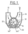
- Figure 1 shows such a pump. It comprises a pump body 10 provided with an intake pipe 12 and a discharge pipe 14 for the liquid.
- An internal gear 16 is pivotally mounted in the pump body 10 around a first axis XX ′. Inside the gear 16 there is a gear 18, for example driving, with external teeth which is rotated about an axis YY ′ parallel to the axis XX ′.
- the gear 18 partially meshes with the gear 16 due to its eccentricity.
- a part 20, whose generatrices are parallel to the axes XX ′ and YY ′ separates over a part of their circumference, the gears 16 and 18.
- the gear 16 has openings 22, corresponding to the tooth bottoms, which allow the liquid to pass from the suction to the internal zone to the gear 16 and from said internal zone to the discharge. Under the effect of the relative rotational movements of the gears 16 and 18, the liquid is sucked from the suction line 12 to the area internal to the gear 16 and then discharged from this internal area to the delivery line 14.
- the principle of such pumps is well known, but their manufacture is delicate and expensive. In particular the manufacture of the external gear with internal teeth, which must allow the mounting of the internal gear with external teeth, is very expensive. In fact, it is impossible to produce this part in its entirety, which has the shape of a squirrel cage by molding or by sintering.
- An object of the present invention is to provide a rotating gear device, in particular a gear pump of the aforementioned type, of which at least the external gear can be produced by molding or by sintering.
- the rotating device for the circulation of liquid which comprises a casing provided with an inlet opening and an outlet opening, and in said casing a first rotating member provided with a rotation axis and an external toothing, and a second rotating member surrounding said first toothing and guided in rotation about a second axis parallel to the first, said second member having an internal toothing to cooperate with a portion of said external toothing and orifices to allow said liquid to penetrate into said second member, is characterized in that said second member consists of two circular rings mounted in said casing in two planes perpendicular to said first axis, and by a plurality of longitudinal elements mounted between said rings parallel to the axis X, X ′, having in cross section the shape of a gear tooth, said longitudinal elements not being integral with said crowns.
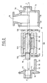
- the pump comprises a body formed by a main casing 30 closed by a flange 32.
- the casing 30 defines a cylindrical cavity 34 of axis XX ′. In the cavity 34 open a suction line 36 visible in Figure 2 and a discharge line not shown.
- the wall 38 of the casing 30 perpendicular to the axis XX ′ has a bearing - stop 40 whose axis YY ′ is offset with respect to the axis XX ′ as shown in FIG. 2.
- the flange 32 the periphery of which 42 can be fixed by any suitable means to the edge 44 casing 30 defines a bearing 46 whose axis coincides with the axis YY ′ when the flange 32 is mounted on the casing 30.
- the flange 32 has on its internal face an extension 48 which defines the half-moon shaped part 20 of the Figure 1.
- the outer face 50 of the extension 48 is a portion of cylinder of revolution with axis XX ′ while its inner face 52 is a portion of cylinder of revolution with axis YY ′.
- the cavity 34 has a generally cylindrical shape limited by the side wall 39 and by two end walls 38 and 41 (flange 32)
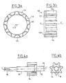
- the external gear referenced 100 comprises two circular end rings 102 and 104 and a plurality of longitudinal elements 106, all identical, which are arranged along the axis XX ′ of the external gear 100.
- Each ring 102 or 104 has on its periphery notches 108 in number equal to the name of the longitudinal elements 106.
- the notches 108 have a depth less than the thickness of the crown 102 or 104 so that the residual thickness serves as an axial stop in the direction XX ′
- the notches 108 are machined to receive the ends of the longitudinal elements 106 with a slight clearance as shown in Figures 3a and 3b.
- the longitudinal elements have, in cross section, the shape of a gear tooth.
- the pump also includes an internal gear 80.
- the gear 80 comprises a shaft 82 to which a pinion 84 with external teeth is fixed.
- the pinion 84 has for example seven teeth which are cut to be able to mesh with the teeth of the external gear formed by the longitudinal elements 106.
- the shaft 82 comprises a first end 86 which forms a bearing for the bearing 40 of the pump body and , on the other side of the pinion 82, a bearing 88 for the bearing 46 of the flange 32 and an end 90 for fixing to a drive member.
- the structure of the external gear 100 is exactly reconstructed.
- the longitudinal elements 106 are held axially by the rings circular 102 and 104 arranged in planes perpendicular to the axis XX ′ and they are held radially by the cylindrical side wall of this same cavity 36.
- the rings 102 and 104 are held in place by the side wall 39 and by the end walls 38 and 41 of the cavity 36.
- the assembly has a slight clearance to absorb the effects of differential thermal expansion.
- the various parts forming the external gear 100 can easily be produced by molding or by sintering (sintered steel).
- the longitudinal elements 106 can be advantageously cut from a Delrin rod having a suitable cross section.
- the longitudinal elements 106 and the notches 108 are limited by portions of cylindrical surfaces of revolution about the same axis, these axes being parallel to the axis X, X ′.
- each longitudinal element guided by the two notches 108 has a reduced possibility of pivoting about its axis when it meshes with a tooth of the internal gear.
- the notches 108 formed in the crowns 102 and 104 can be the entire thickness of these.
- the longitudinal elements 106 are held longitudinally by the internal walls of the casing and of the flange perpendicular to the axis XX ′.
Landscapes
- Engineering & Computer Science (AREA)
- Mechanical Engineering (AREA)
- General Engineering & Computer Science (AREA)
- Rotary Pumps (AREA)
- Details And Applications Of Rotary Liquid Pumps (AREA)
Applications Claiming Priority (2)
| Application Number | Priority Date | Filing Date | Title |
|---|---|---|---|
| FR8806920A FR2632020B1 (fr) | 1988-05-25 | 1988-05-25 | Dispositif tournant a engrenages pour la circulation d'un liquide |
| FR8806920 | 1988-05-25 |
Publications (2)
| Publication Number | Publication Date |
|---|---|
| EP0344059A1 true EP0344059A1 (de) | 1989-11-29 |
| EP0344059B1 EP0344059B1 (de) | 1991-07-31 |
Family
ID=9366578
Family Applications (1)
| Application Number | Title | Priority Date | Filing Date |
|---|---|---|---|
| EP89401408A Expired - Lifetime EP0344059B1 (de) | 1988-05-25 | 1989-05-24 | Rotierende Zahnradvorrichtung zur Förderung einer Flüssigkeit |
Country Status (5)
| Country | Link |
|---|---|
| US (1) | US4958996A (de) |
| EP (1) | EP0344059B1 (de) |
| DE (1) | DE68900174D1 (de) |
| ES (1) | ES2025849T3 (de) |
| FR (1) | FR2632020B1 (de) |
Families Citing this family (3)
| Publication number | Priority date | Publication date | Assignee | Title |
|---|---|---|---|---|
| US20130071280A1 (en) * | 2011-06-27 | 2013-03-21 | James Brent Klassen | Slurry Pump |
| CA2907702C (en) | 2013-03-21 | 2022-03-15 | James Klassen | Slurry pump |
| US11067076B2 (en) | 2015-09-21 | 2021-07-20 | Genesis Advanced Technology Inc. | Fluid transfer device |
Citations (2)
| Publication number | Priority date | Publication date | Assignee | Title |
|---|---|---|---|---|
| GB270000A (en) * | 1926-02-02 | 1927-05-02 | Stone J & Co Ltd | Improvements in rotary engines, pumps, blowers, compressors, meters and the like |
| US2621603A (en) * | 1948-08-31 | 1952-12-16 | Julian B Thomas | Rotary pump |
Family Cites Families (7)
| Publication number | Priority date | Publication date | Assignee | Title |
|---|---|---|---|---|
| DE325849C (de) * | 1917-03-03 | 1920-09-21 | Emil Ludwig | Zahnradpumpe, bei welcher ein Stirnrad mit einem innen verzahnten Hohlrad zusammenarbeitet |
| US1496737A (en) * | 1922-06-03 | 1924-06-03 | Viking Pump Company | Rotary pump, motor, or engine |
| US2672824A (en) * | 1944-05-11 | 1954-03-23 | Gerotor May Corp | Hydraulic pump or motor |
| US2601397A (en) * | 1950-04-11 | 1952-06-24 | Hill Myron Francis | Rotary fluid displacement device |
| US2615399A (en) * | 1950-09-09 | 1952-10-28 | Peerless Machinery Co | Rotary pump |
| US3233524A (en) * | 1962-09-05 | 1966-02-08 | Germane Corp | Fluid operated motor |
| US3276288A (en) * | 1963-12-20 | 1966-10-04 | Fry Jeremy Joseph | Housing for valve actuator or the like |
-
1988
- 1988-05-25 FR FR8806920A patent/FR2632020B1/fr not_active Expired - Fee Related
-
1989
- 1989-05-23 US US07/355,581 patent/US4958996A/en not_active Expired - Lifetime
- 1989-05-24 EP EP89401408A patent/EP0344059B1/de not_active Expired - Lifetime
- 1989-05-24 DE DE8989401408T patent/DE68900174D1/de not_active Expired - Fee Related
- 1989-05-24 ES ES198989401408T patent/ES2025849T3/es not_active Expired - Lifetime
Patent Citations (2)
| Publication number | Priority date | Publication date | Assignee | Title |
|---|---|---|---|---|
| GB270000A (en) * | 1926-02-02 | 1927-05-02 | Stone J & Co Ltd | Improvements in rotary engines, pumps, blowers, compressors, meters and the like |
| US2621603A (en) * | 1948-08-31 | 1952-12-16 | Julian B Thomas | Rotary pump |
Also Published As
| Publication number | Publication date |
|---|---|
| ES2025849T3 (es) | 1992-04-01 |
| FR2632020A1 (fr) | 1989-12-01 |
| EP0344059B1 (de) | 1991-07-31 |
| DE68900174D1 (de) | 1991-09-05 |
| US4958996A (en) | 1990-09-25 |
| FR2632020B1 (fr) | 1994-02-11 |
Similar Documents
| Publication | Publication Date | Title |
|---|---|---|
| EP3495692B1 (de) | Krone eines untersetzungsgetriebes mit planetensatz für strömungsmaschine | |
| EP1855005B1 (de) | Rotationsverdrängerpumpe mit beschränktem radialem Raumbedarf | |
| FR2530742A1 (fr) | Compresseur volumetrique a vis | |
| WO2018197645A1 (fr) | Porte-satellites a cage pour un reducteur de vitesse a train epicycloïdal | |
| WO2008061929A1 (fr) | Cartouche de filtration destinée à coopérer avec un tube central, comprenant un joint d'étanchéité monté dans une cavité pour coopérer avec ledit tube, ledit joint étant retenu radialement | |
| EP4185790A1 (de) | Getriebegehäuse, getriebe und radfahrzeug mit solch einem getriebe | |
| FR2668209A1 (fr) | Pompe d'aspiration moleculaire. | |
| EP0344059B1 (de) | Rotierende Zahnradvorrichtung zur Förderung einer Flüssigkeit | |
| EP3252540B1 (de) | Motororgan für uhr | |
| EP3572238B1 (de) | Nabe für ein fahrradrad | |
| EP0736691B1 (de) | Innenzahnradpumpe mit radialen Zuführungsröhren | |
| FR2665487A1 (fr) | Agregat pour refouler du carburant a partir d'un reservoir vers le moteur a combustion interne d'un vehicule automobile. | |
| EP3268610B1 (de) | Zahnradpumpe für komprimierbare flüssigkeiten oder fluids | |
| FR2586066A1 (fr) | Pompe a huile | |
| BE1027453B1 (fr) | Pompe a engrenage | |
| EP0249511B2 (de) | Anzeigeapparat mit Zeiger und Indexierungshülse dafür | |
| EP1946050B1 (de) | Zylindrische messkammer eines wassermessers | |
| FR2492474A1 (fr) | Pompe a rotor excentre | |
| FR2748068A1 (fr) | Pompe rotative a palettes | |
| FR2611834A1 (fr) | Dispositif de montage a rotation d'un pignon par rapport a un bati | |
| EP1491797A1 (de) | Implantation einer Ölpumpe in einem Getriebegehäuse eines Automobils | |
| FR2510673A1 (fr) | Groupe moto-pompe, notamment pour dispositif d'assistance de direction d'un vehicule automobile | |
| FR2497880A1 (fr) | Pompe a engrenages | |
| EP3685046A1 (de) | Pumpe mit variabler fördermenge und kreislauf mit einer solchen pumpe | |
| EP1719641A1 (de) | Fahrzeugradnabe, Fahrzeugrad und Rahmen eine solche Nabe enthaltend |
Legal Events
| Date | Code | Title | Description |
|---|---|---|---|
| PUAI | Public reference made under article 153(3) epc to a published international application that has entered the european phase |
Free format text: ORIGINAL CODE: 0009012 |
|
| AK | Designated contracting states |
Kind code of ref document: A1 Designated state(s): BE CH DE ES GB IT LI NL SE |
|
| 17P | Request for examination filed |
Effective date: 19900111 |
|
| 17Q | First examination report despatched |
Effective date: 19901031 |
|
| GRAA | (expected) grant |
Free format text: ORIGINAL CODE: 0009210 |
|
| AK | Designated contracting states |
Kind code of ref document: B1 Designated state(s): BE CH DE ES GB IT LI NL SE |
|
| REF | Corresponds to: |
Ref document number: 68900174 Country of ref document: DE Date of ref document: 19910905 |
|
| ITF | It: translation for a ep patent filed | ||
| GBT | Gb: translation of ep patent filed (gb section 77(6)(a)/1977) | ||
| REG | Reference to a national code |
Ref country code: ES Ref legal event code: FG2A Ref document number: 2025849 Country of ref document: ES Kind code of ref document: T3 |
|
| PGFP | Annual fee paid to national office [announced via postgrant information from national office to epo] |
Ref country code: CH Payment date: 19920514 Year of fee payment: 4 |
|
| PGFP | Annual fee paid to national office [announced via postgrant information from national office to epo] |
Ref country code: ES Payment date: 19920519 Year of fee payment: 4 |
|
| PGFP | Annual fee paid to national office [announced via postgrant information from national office to epo] |
Ref country code: SE Payment date: 19920526 Year of fee payment: 4 |
|
| PLBE | No opposition filed within time limit |
Free format text: ORIGINAL CODE: 0009261 |
|
| STAA | Information on the status of an ep patent application or granted ep patent |
Free format text: STATUS: NO OPPOSITION FILED WITHIN TIME LIMIT |
|
| PGFP | Annual fee paid to national office [announced via postgrant information from national office to epo] |
Ref country code: BE Payment date: 19920616 Year of fee payment: 4 |
|
| 26N | No opposition filed | ||
| PG25 | Lapsed in a contracting state [announced via postgrant information from national office to epo] |
Ref country code: SE Effective date: 19930525 Ref country code: ES Free format text: LAPSE BECAUSE OF NON-PAYMENT OF DUE FEES Effective date: 19930525 |
|
| PG25 | Lapsed in a contracting state [announced via postgrant information from national office to epo] |
Ref country code: LI Effective date: 19930531 Ref country code: CH Effective date: 19930531 Ref country code: BE Effective date: 19930531 |
|
| BERE | Be: lapsed |
Owner name: SCHLUMBERGER INDUSTRIES Effective date: 19930531 |
|
| REG | Reference to a national code |
Ref country code: CH Ref legal event code: PL |
|
| EUG | Se: european patent has lapsed |
Ref document number: 89401408.3 Effective date: 19931210 |
|
| REG | Reference to a national code |
Ref country code: ES Ref legal event code: FD2A Effective date: 19990503 |
|
| REG | Reference to a national code |
Ref country code: GB Ref legal event code: 732E |
|
| PGFP | Annual fee paid to national office [announced via postgrant information from national office to epo] |
Ref country code: GB Payment date: 20000525 Year of fee payment: 12 |
|
| PGFP | Annual fee paid to national office [announced via postgrant information from national office to epo] |
Ref country code: NL Payment date: 20000530 Year of fee payment: 12 |
|
| PGFP | Annual fee paid to national office [announced via postgrant information from national office to epo] |
Ref country code: DE Payment date: 20000830 Year of fee payment: 12 |
|
| NLS | Nl: assignments of ep-patents |
Owner name: TOKHEIM SERVICES FRANCE |
|
| PG25 | Lapsed in a contracting state [announced via postgrant information from national office to epo] |
Ref country code: GB Free format text: LAPSE BECAUSE OF NON-PAYMENT OF DUE FEES Effective date: 20010524 |
|
| PG25 | Lapsed in a contracting state [announced via postgrant information from national office to epo] |
Ref country code: NL Free format text: LAPSE BECAUSE OF NON-PAYMENT OF DUE FEES Effective date: 20011201 |
|
| GBPC | Gb: european patent ceased through non-payment of renewal fee |
Effective date: 20010524 |
|
| NLV4 | Nl: lapsed or anulled due to non-payment of the annual fee |
Effective date: 20011201 |
|
| PG25 | Lapsed in a contracting state [announced via postgrant information from national office to epo] |
Ref country code: DE Free format text: LAPSE BECAUSE OF NON-PAYMENT OF DUE FEES Effective date: 20020405 |
|
| PG25 | Lapsed in a contracting state [announced via postgrant information from national office to epo] |
Ref country code: IT Free format text: LAPSE BECAUSE OF NON-PAYMENT OF DUE FEES;WARNING: LAPSES OF ITALIAN PATENTS WITH EFFECTIVE DATE BEFORE 2007 MAY HAVE OCCURRED AT ANY TIME BEFORE 2007. THE CORRECT EFFECTIVE DATE MAY BE DIFFERENT FROM THE ONE RECORDED. Effective date: 20050524 |