EP0343982B1 - Gerät zur Aufzeichnung und/oder Wiedergabe von Information - Google Patents
Gerät zur Aufzeichnung und/oder Wiedergabe von Information Download PDFInfo
- Publication number
- EP0343982B1 EP0343982B1 EP19890305292 EP89305292A EP0343982B1 EP 0343982 B1 EP0343982 B1 EP 0343982B1 EP 19890305292 EP19890305292 EP 19890305292 EP 89305292 A EP89305292 A EP 89305292A EP 0343982 B1 EP0343982 B1 EP 0343982B1
- Authority
- EP
- European Patent Office
- Prior art keywords
- recording medium
- holding means
- information
- optical card
- recording
- Prior art date
- Legal status (The legal status is an assumption and is not a legal conclusion. Google has not performed a legal analysis and makes no representation as to the accuracy of the status listed.)
- Expired - Lifetime
Links
Images


Classifications
-
- G—PHYSICS
- G06—COMPUTING OR CALCULATING; COUNTING
- G06K—GRAPHICAL DATA READING; PRESENTATION OF DATA; RECORD CARRIERS; HANDLING RECORD CARRIERS
- G06K19/00—Record carriers for use with machines and with at least a part designed to carry digital markings
- G06K19/04—Record carriers for use with machines and with at least a part designed to carry digital markings characterised by the shape
- G06K19/041—Constructional details
- G06K19/042—Constructional details the record carrier having a form factor of a credit card and including a small sized disc, e.g. a CD or DVD
- G06K19/044—Constructional details the record carrier having a form factor of a credit card and including a small sized disc, e.g. a CD or DVD comprising galvanic contacts for contacting an integrated circuit chip thereon
-
- G—PHYSICS
- G06—COMPUTING OR CALCULATING; COUNTING
- G06K—GRAPHICAL DATA READING; PRESENTATION OF DATA; RECORD CARRIERS; HANDLING RECORD CARRIERS
- G06K7/00—Methods or arrangements for sensing record carriers, e.g. for reading patterns
- G06K7/10—Methods or arrangements for sensing record carriers, e.g. for reading patterns by electromagnetic radiation, e.g. optical sensing; by corpuscular radiation
-
- G—PHYSICS
- G11—INFORMATION STORAGE
- G11B—INFORMATION STORAGE BASED ON RELATIVE MOVEMENT BETWEEN RECORD CARRIER AND TRANSDUCER
- G11B17/00—Guiding record carriers not specifically of filamentary or web form, or of supports therefor
- G11B17/02—Details
-
- G—PHYSICS
- G11—INFORMATION STORAGE
- G11B—INFORMATION STORAGE BASED ON RELATIVE MOVEMENT BETWEEN RECORD CARRIER AND TRANSDUCER
- G11B17/00—Guiding record carriers not specifically of filamentary or web form, or of supports therefor
- G11B17/02—Details
- G11B17/04—Feeding or guiding single record carrier to or from transducer unit
- G11B17/0408—Feeding or guiding single record carrier to or from transducer unit of non-disc record carrier, e.g. card
-
- G—PHYSICS
- G11—INFORMATION STORAGE
- G11B—INFORMATION STORAGE BASED ON RELATIVE MOVEMENT BETWEEN RECORD CARRIER AND TRANSDUCER
- G11B19/00—Driving, starting, stopping record carriers not specifically of filamentary or web form, or of supports therefor; Control thereof; Control of operating function ; Driving both disc and head
- G11B19/02—Control of operating function, e.g. switching from recording to reproducing
-
- G—PHYSICS
- G11—INFORMATION STORAGE
- G11B—INFORMATION STORAGE BASED ON RELATIVE MOVEMENT BETWEEN RECORD CARRIER AND TRANSDUCER
- G11B19/00—Driving, starting, stopping record carriers not specifically of filamentary or web form, or of supports therefor; Control thereof; Control of operating function ; Driving both disc and head
- G11B19/20—Driving; Starting; Stopping; Control thereof
-
- G—PHYSICS
- G11—INFORMATION STORAGE
- G11B—INFORMATION STORAGE BASED ON RELATIVE MOVEMENT BETWEEN RECORD CARRIER AND TRANSDUCER
- G11B25/00—Apparatus characterised by the shape of record carrier employed but not specific to the method of recording or reproducing, e.g. dictating apparatus; Combinations of such apparatus
- G11B25/04—Apparatus characterised by the shape of record carrier employed but not specific to the method of recording or reproducing, e.g. dictating apparatus; Combinations of such apparatus using flat record carriers, e.g. disc, card
- G11B25/046—Apparatus characterised by the shape of record carrier employed but not specific to the method of recording or reproducing, e.g. dictating apparatus; Combinations of such apparatus using flat record carriers, e.g. disc, card using stationary discs, or cards provided with a circular recording area
Definitions
- the present invention relates to an ejecting mechanism of an information recording medium in, for instance, an optical information recording and/or reproducing apparatus for recording and/or reproducing information by using an information recording medium having, for instance, a rectangular shape other than a circular shape.
- optical information recording media Hitherto, a read only compact disc, a write once and read mostly (WORM) type optical disk, and the like have been known as optical information recording media.
- an information processing system using a card-shaped optical recording medium which is superior to the disk-shaped recording medium in terms of portability, i.e., what is called an optical card has been also highlighted.
- an optical recording medium in which concentric or spiral information tracks are formed on the surface of a rectangular card has been disclosed in Japanese Kokai 62-264458.
- An information recording and reproducing apparatus using such a medium has been disclosed in Japanese Kokai 63-31084.
- Fig. 1 is a plan view of an optical card C having an almost rectangular card shape.
- the size of optical card C is not particularly limited, it is preferably set into a size such that the card can be enclosed in a pocket, purse, or the like and in the case of carrying the card, it does not become too large nor small. For instance, the size is set into approximately 85.6 mm x 54.0 mm.
- a circular recording area D in which a center position O of the optical card C is used as a center is formed on the surface of the optical card C. A number of concentric or spiral information tracks are arranged in the recording area D.
- Fig. 2 is a perspective view of an optical information reproducing apparatus for reproducing information by rotating the optical card C.
- a turntable 1 onto which the optical card C is put is rotated by a spindle motor 2 attached below the turntable 1.
- a guide groove 3 having a width which is fairly larger than a length of short side of the optical card C is formed on the upper surface of the turntable 1.
- a leaf spring 4 is attached to one wall of the guide groove 3.
- the optical card C is put on the guide groove 3
- the card is pressed to the other wall of the guide groove 3 by the leaf spring 4.
- a pin-shaped stopper 5 is provided at one end of the guide groove 3.
- a lever 7 is rotatably attached at the other end of the guide groove 3 at a position around a pin 6 provided in the outside of the guide groove 3 on the turntable 1.
- One end of a coil spring 8 is attached to the turntable 1.
- the other end of the coil spring 8 is connected to the lever 7.
- the operational edge of the lever 7 presses the optical card C on the guide groove 3 to the stopper 5 by the tensile force of the coil spring 8.
- the insertion and ejection of the optical card C into and from the turntable 1 are executed in a state in which the lever 7 is rotated around the pin 6 against the tensile force of the coil spring 8 and the operational edge of the lever 7 is moved out of the guide groove 3.
- the optical card C is inserted in the direction of an arrow X in the guide groove 3 and is moved to a position where the front edge of the card abuts on the stopper 5 while being pressed to the wall on the opposite side by the leaf spring 4. Thereafter, the lever 7 is come into contact with the card C and the card is fixed.
- the center position O of the recording area D is located onto the axial center of the rotating shaft of the spindle motor 2.
- a feed screw 9 and a guide rail 10 are attached in parallel in the horizontal direction over the turntable 1.
- An optical head 11 is movably mounted to the feed screw 9 and guide rail 10.
- a female screw which is come into engagement with the feed screw 9 is provided in the optical head 11.
- the optical head 11 is slidably attached to the guide rail 10.
- the optical card C is ejected out in a state in which the operational edge of the lever 7 is moved out of the guide groove 3 as mentioned above.
- the direction of the guide groove 3 needs to be accurately made coincide with the ejecting conveying direction of the optical card C. If the matching accuracy in this case is low, not only a conveyance error occurs but also there is a danger such that the optical card C itself will be damaged.
- optical cards there have been proposed many optical cards on each of which a mark such as characters, photograph, or the like is printed so that the operator can check the content of the optical card by the eyes.
- a method is also convenient upon operation.
- the above information recording and/or reproducing apparatus does not have means for accurately directing the optical card in the ejecting direction, so that such an operation cannot be executed and it is inconvenient.
- European Patent Specification EP-A-230069 discloses an information recording/reproduction system using a card-like recording member but makes no mention of ensuring that the recording member is correctly aligned in the discharge direction.
- European Patent Specification EP-A-229720 has an earlier priority date than the present application and its contents are accordingly, pursuant to Articles 54(3) and (4) EPC, comprised in the state of the art relative to the present invention.
- this specification utilises physical means for stopping the rotation of the recording medium in order to try and ensure that it is correctly aligned for discharge.
- the present invention is concerned with providing an information recording and/or reproducing apparatus having an ejecting mechanism for an information recording medium in which by providing means for accurately directing the information recording medium in the ejection direction, the information recording medium can be ejected without damage.
- the present invention provides information recording apparatus as set out in claim 1.
- the present invention provides information reproducing apparatus as set out in claim 2.
- the present invention provides information recording/reproducing apparatus as set out in claim 3.
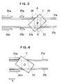
- FIG. 3 shows the first embodiment.
- a conveying base plate 22 is slidably mounted to two parallel rails 21a and 21b whose both ends are fixed to the main body of an information recording and/or reproducing apparatus.
- the conveying base plate 22 can be reciprocated by a linear motor (not shown) in the region from an optical card inserting/ejecting port of the apparatus on the left side in the drawing to a position A - A′ to record and/or reproduce information by an optical head (not shown).
- a turntable 23 onto which the optical card C is put and a spindle motor (not shown) to rotate the turntable 23 are mounted on the base plate 22.
- An outer diameter of the turntable 23 is smaller than a length of short side of the optical card C.
- the optical card C is set so that the center position O of the optical card C is located on the axial center of a center shaft 23a of the turntable 23.
- the optical card C is then fixed by a clamper from the upper position.
- An interval between the rails 21a and 21b including the widths of the rails themselves is set to be almost equal to the length of the short side of the optical card C.
- Fixed guides 24a and 24b are arranged on both outsides of the rails 21a and 21b near the inserting/ejecting port of the optical card C with an interval which is slightly wider than the length of the short side of the optical card C.
- two auxiliary guides 25a and 25b are arranged on the insides along the rails 21a and 21b so as to face each other.
- the auxiliary guides 25a and 25b can move in the upper and lower directions, that is, in the directions perpendicular to the surface of the drawing paper. Namely, the guides 25a and 25b can move in the directions which are perpendicular to the surface of the recording medium on the optical card C.
- the guides 25a and 25b have the side portions which are parallel with the rails 21a and 21b and also have guide portions whose inward sides are arc-shaped.
- the rotation of the turntable 23 is stopped at the position A - A′ where information is recorded and/or reproduced onto/from the optical card C and the direction of the optical card C, that is, the rotating position of the optical card is detected by a sensor 26.
- the sensor 26 is arranged on the outside of the rail 21a and at a position where the distance form the turntable center shaft 23a is shorter than the length which is 1/2 of the length of the long side of the optical card C.
- the sensor 26 comprises a photo reflector, photo interruptor, or the like and detects whether the optical card C exists over the sensor 26 or not when the rotation of the turntable 23 is stopped. In other words, the sensor 26 detects the direction, an angular position of the optical card C on the turntable 23.
- a detection output of the sensor 26 is supplied to a drive control unit of the auxiliary guides 25a and 25b.
- the guide 25a or 25b is selectively driven in the vertical direction.
- the sensor 26 can be also attached over the conveying base plate 22 without fixing to the apparatus main body.
- the optical card C inserted from the optical card inserting port is set onto the turntable 23 and is moved to the operational position A - A′ of the optical head while the rotation of the card is restricted by the fixed guides 24a and 24b and the auxiliary guides 25a and 25b.
- the rotation of the turntable 23 is stopped by the stop of the rotation of the spindle motor.
- the conveying base plate 22 starts moving in the direction (X direction in the diagram) of the optical card ejecting port along the rails 21a and 21b. In this case, the long side of the optical card C is not always parallel with the rails 21a and 21b.
- the long side of the optical card C is directed obliquely to the rails 21a and 21b. Therefore, in such a state, the optical card C cannot pass through the region between the fixed guides 24a and 24b.
- the direction of the optical card C is detected by the sensor 26 when the turntable 23 stops. If the optical card C exists over the sensor 26, the auxiliary guide 25a is put down. Next, by stopping the current supply to the clamper and/or spindle motor of the optical card C, the optical card C is set into the freely rotatable state. Then, the movement of the conveying base plate 22 is started. Thus, as shown in Fig. 5, the long side portion of the optical card C is rotated in contact relation with the auxiliary guide 25b and is adjusted to the direction parallel with the rails 21a and 21b. Then, the optical card C is led to the region between the fixed guides 24a and 24b. On the contrarily, if the optical card C does not exist over the sensor 26, by putting down the auxiliary guide 25b contrarily, the similar direction control can be executed.
- Fig. 6 shows the second embodiment and the same parts and components as those shown in Fig. 3 are designated by the same reference numerals.
- a fixed guide 24b′ is slightly longer on the inner side than the opposite fixed guide 24a.
- the edge portion of the fixed guide 24b′ serves as a curved guide portion.
- a sensor 27 is arranged at a position where the distance from the center shaft 23a of the turntable 23 in the outside portion of the rail 21a is slightly shorter than 1/2 of the length of the long side of the optical card C when the optical card C rotates in the direction of an arrow R at the operational position A - A′ of the optical head.
- the sensor 27 comprises a photo interruptor in which an LED and a phototransistor are arranged so as to face each other.
- the optical card C as a light shielding object passes through the region between the LED and the phototransistor.
- the sensor 27 can detect the passage of long side portions C1 and C2 of the rotating optical card C.
- a detection output of the sensor 27 is input to a control unit using a linear motor to drive the conveying base plate 22.
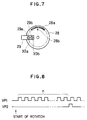
- Fig. 7 shows an optical rotary encoder which is used in the second embodiment.
- the rotary encoder is attached to the spindle motor to rotate the turntable onto which the optical card C is put.
- the rotary encoder comprises: a slit plate 28 which is attached to the center shaft 23a of the turntable 23 and is rotated; and a photo interruptor 29 attached to a fixed portion of the spindle motor.
- a slit 28a having 360 windows per circumference is formed in the outer peripheral portion of the slit plate 28.
- a slit 28b having one window per circumference is arranged in the inner peripheral portion of the slit plate 28.
- a first LED (not shown) and a first phototransistor 30a are arranged so as to face the photo interruptor 29 through a fixed slit 29a.
- a second LED (not shown) and a second phototransistor 30b are arranged so as to face the photo interruptor 29 through a fixed slit 29b.
- the fixed slits 29a and 29b are arranged so as to face the slits 28a and 28b of the slit plate 28.
- Outputs of the first and second phototransistors 30a and 30b are input to the control unit of the linear motor to drive the conveying base plate 22.
- the optical card C upon loading, the optical card C is moved in parallel to the operational position by the operation similar to that in the first embodiment and starts rotating in the direction of the arrow R.
- 360 pulses are output per revolution from the first phototransistor 30a by the light fluxes which passed through the slit plate 28 and one pulse is output per revolution from the second phototransistor 30b.
- Fig. 8 shows output pulses VP1 and VP2 of the first and second phototransistors 30a and 30b of the photo interruptor 29.
- n pulses VP1 are output from the start time point of the revolution, the optical card C has rotated n degrees until the time point of the generation of the n-th pulse.
- a numerical value of the pulses VP1 detected is sent to the control unit of the linear motor. Thereafter, information is recorded and/or reproduced while rotating the optical card C at an angular velocity of, for instance, 1000 r.p.m.
- the time point when the sensor 27 detects the long side portion C1 which was on the right hand side during inserting movement of the optical card C coincides with the time point when the optical card C has rotated by only the rotational angle of (360 - n - ⁇ )° after completion of the generation of each pulse VP2, that is, the time point when (360 - n - ⁇ ) pulses VP1 were output.
- n 90° and ⁇ equals 45°
- sensor 27 will detect side C1 at 225 pulses of VP1 after VP2. Therefore in this case, the angular velocity of the optical card C is first reduced to 60 r.p.m. and the output of the sensor 27 is made effective within only the period of time when the 200th to 250th pulses VP1 are output after the pulse VP2 was output. From the time point when the effective output of the sensor 27 was obtained, the control unit of the linear motor starts moving the conveying base plate 22 in parallel.
- the card is ejected out in a state in which its direction is the same as that upon insertion.
- the current supply to the clamper and/or spindle motor of the optical card C is stopped.
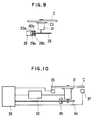
- Fig. 9 shows the third embodiment.
- a rotary encoder is attached to a spindle motor 31 to rotate the optical card C.
- the rotary encoder comprises: the slit plate 28 which is attached to a center shaft of the spindle motor 31 and is rotated; and the photo interruptor 29 attached to a fixed portion of the spindle motor 31.
- the slit 28a having, for instance, 360 windows per circumference is formed in the outer peripheral portion of the slit plate 28.
- the slit 28b having one window per circumference is formed in the inner peripheral portion of the slit plate 28.
- the first LED (not shown) and the first phototransistor 30a are arranged so as to face the photo interruptor 29 through the fixed slit 29a.
- the second LED (not shown) and the second phototransistor 30b are arranged so as to face the photo interruptor 29 through the fixed slit 29b.
- the fixed slits 29a and 29b are arranged so as to face the slits 28a and 28b of the slit plate 28.
- the optical card C starts rotating.
- the spindle motor 31 rotates, 360 pulses are output per revolution from the first phototransistor 30a and one pulse is output per revolution from the second phototransistor 30b by the light fluxes which passed through the slit plate 28.
- Fig. 8 shows the output pulses VP1 and VP2 of the first and second phototransistors 30a and 30b of the photo interruptor 29.
- the control unit transmits a brake command, thereby enabling the ejecting direction of the optical card C to be correctly adjusted.
- the optical card C can be also stopped in the correct direction by the control unit to control the spindle motor in correspondence to the signal from the encoder.
- Figs. 10 to 13 show the fourth embodiment.
- Fig. 10 shows a mechanism to adjust the ejecting direction of the optical card C.
- the spindle motor 31 to rotate the optical card C is connected to a control unit 33 through a motor driver 32 and is driven and stopped by a command from the control unit 33.
- a rotary encoder comprising a slit plate 34 and a photo interruptor 35 is attached to the spindle motor 31. Pulses of the frequency which is proportional to the rotating speed of the slit plate 34 are obtained from the photo interruptor 35 and transmitted to the control unit 33.
- two photosensors 36 and 37 of the light reflection type are arranged below the rotating optical card C. Outputs of the photosensors 36 and 37 are input to the control unit 33.
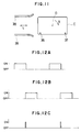
- Fig. 11 is a plan view showing an arranging positions of the photosensors 36 and 37.
- the photosensors 36 and 37 are arranged so as to detect two adjacent edge portions of the optical card C when the rotating direction of the optical card C coincides with an ejecting direction L along guide rails 38 and 39.
- Fig. 12A shows a signal from the photosensor 36.
- Fig. 12B shows a signal from the photosensor 37.
- the signals of the photosensors 36 and 37 are set to the high level only for the period of time when the optical card C traverses over the sensors 36 and 37.
- Fig. 12C shows a signal indicative of the AND of the signals of Figs. 12A and 12B. Therefore, when the AND signal of Fig. 12C is at the high level, the direction of the optical card C coincides with the ejecting direction L as shown in Fig. 11.
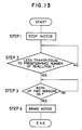
- Fig. 13 is a flowchart showing a procedure to align the rotation stopping direction of the optical card C.
- step 1 the power supply to the spindle motor 31 is stopped.
- step 2 a check is made to see if the speed of revolution of the spindle motor 31 is less than or equal to a predetermined speed of revolution or not. Only when it is less than or equal to the predetermined speed of revolution, step 3 follows. Only when both of the signals of the photo-sensors 36 and 37 are at the high level in step 3, step 4 follows.
- step 4 a brake signal is transmitted to the motor driver 32 and the processing routine is finished.
- the angle between the stopping direction of the optical card C and the ejecting direction L can be adjusted to a value within a range of about ⁇ 2°. Therefore, as shown in Fig. 11, by slightly widening the edge portions of the guide rails 38 and 39, the optical card C can be certainly ejected out.
- the photosensors 36 and 37 are provided, the presence or absence of the optical card C can be also detected from an output signal upon rotation of the spindle motor 31.
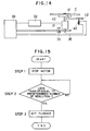
- FIGs. 14 and 15 show the fifth embodiment.
- a notched portion 41 is formed at a predetermined position on the lower surface of a turntable 40 onto which the optical card C is put.
- a stopper 42 having a tip edge portion adapted to be fitted into the notched portion 41 is arranged below the turntable 40.
- the stopper 42 is vertically driven by a plunger 43 which is made operative by the control unit 33.
- Fig. 15 is a flowchart showing a procedure to align the rotation stopping direction.
- step 1 the power supply of the spindle motor 31 is disconnected. Only when the speed of revolution of the spindle motor 31 is equal to or less than a predetermined speed of revolution in step 2, step 3 follows.
- step 3 the plunger 43 is made operative.
- the control unit 33 waits until the speed of revolution of the spindle motor 31 is equal to or less than the predetermined speed of revolution.
- the plunger 43 is made operative to upwardly move the stopper 42 in the direction which is parallel with the rotating shaft of the spindle motor 31.
- the rotation of the spindle motor is stopped at the position where the stopper 42 is fitted into the notched portion 41. Due to the stop of the rotation, the turntable 40 is set to a predetermined direction, that is, the longitudinal direction of the optical card C coincides with the direction of the guide rails 38 and 39.
- the tip edge portion of the stopper 42 is come into slide contact with the lower surface of the turntable 40 until it is fitted into the notched portion 41, it is necessary to set the predetermined speed of revolution to a slightly high value to thereby prevent that the rotation of the spindle motor is stopped during the slide contact motion by the friction between the lower surface of the turntable 40 and the tip edge portion of the stopper 42.
- the plunger 43 is made inoperative to release the stopper 42.
- the notched portion 41 has been formed on the lower surface of the turntable 40.
- Fig. 16 shows the sixth embodiment.
- Magnets 51 and 52 as magnetic flux generating means are arranged so as to face each other in the outer peripheral portion of a turntable 50.
- Magnetic poles of the magnets 51 and 52 are arranged so that the S and N poles are directed to the outsides.
- electromagnets 53 and 54 to form magnetic fields by generating magnetic fluxes by current flowing through their coils are fixed to the main body base plate of the apparatus at positions where the turntable 50 is sandwiched on the straight line which is perpendicular to the rotating shaft of the turntable 50 and to the ejecting direction L of the optical card C.
- the magnetic poles of the electromagnets 53 and 54 are arranged so that the N and S poles are directed to the insides.
- the shape of the information recording medium is not particularly limited.
- the invention can be also applied to other information recording media having any shapes such as circular shape, square shape, and the like if they are the information recording media such that the ejecting direction and the inserting direction of the information recording medium need to be coincident or such that when the information recording medium is ejected out, the direction of the medium needs to be aligned to a predetermined direction.
- the direction of the information recording medium can be indirectly known. Therefore, the direction of holding means for holding the information recording medium may be also detected in place of the direction of the medium.
- the information recording and/or reproducing apparatus of the present invention in spite of the fact that it has the mechanism to rotate the information recording medium and to read out the information therefrom, the ejecting direction of the information recording medium can be made coincident with the inserting direction. Therefore, the apparatus can be easily handled. A danger such that the recording medium is damaged can be prevented. The reliability of the automatic ejecting function can be raised.
Landscapes
- Engineering & Computer Science (AREA)
- Physics & Mathematics (AREA)
- Theoretical Computer Science (AREA)
- General Physics & Mathematics (AREA)
- General Health & Medical Sciences (AREA)
- Toxicology (AREA)
- Artificial Intelligence (AREA)
- Computer Vision & Pattern Recognition (AREA)
- Electromagnetism (AREA)
- Health & Medical Sciences (AREA)
- Computer Hardware Design (AREA)
- Microelectronics & Electronic Packaging (AREA)
- Conveying Record Carriers (AREA)
- Optical Recording Or Reproduction (AREA)
Claims (8)
- Informations-Aufzeichnungsvorrichtung mit
einem Kopf (11) zum Ausführen einer Aufzeichnung von Informationen auf einem nicht kreisförmigen kartenähnlichen Informations-Aufzeichnungsmedium (C),
einer Haltevorrichtung (23) zum Halten des Aufzeichnungsmediums,
einer Antriebsvorrichtung zum Drehen der Haltevorrichtung derart, daß die Aufzeichnung von Informationen auf dem Aufzeichnungsmedium durch den Kopf ausgeführt werden kann,
einer Erfassungseinrichtung (27) zum Erfassen einer Winkelstellung des Aufzeichnungsmediums oder der Haltevorrichtung und
einer Steuereinrichtung (33) zum Steuern der Antriebsvorrichtung entsprechend einem Ausgangssignal aus der Erfassungseinrichtung zum Einstellen der Winkelstellung der Haltevorrichtung, damit die Längsrichtung des Aufzeichnungsmediums auf eine Ausstoßrichtung ausgerichtet wird, wenn das Aufzeichnungsmedium aus der Vorrichtung ausgestoßen wird. - Informations-Wiedergabevorrichtung mit
einem Kopf (11) zum Ausführen einer Wiedergabe von Informationen von einem nicht kreisförmigen kartenähnlichen Informations-Aufzeichnungsmedium (C),
einer Haltevorrichtung (23) zum Halten des Aufzeichnungsmediums,
einer Antriebsvorrichtung zum Drehen der Haltevorrichtung derart, daß die Wiedergabe von Informationen von dem Aufzeichnungsmedium durch den Kopf ausgeführt werden kann,
einer Erfassungseinrichtung (27) zum Erfassen einer Winkelstellung des Aufzeichnungsmediums oder der Haltevorrichtung und
einer Steuereinrichtung (33) zum Steuern der Antriebsvorrichtung entsprechend einem Ausgangssignal aus der Erfassungseinrichtung zum Einstellen der Winkelstellung der Haltevorrichtung, damit die Längsrichtung des Aufzeichnungsmediums auf eine Ausstoßrichtung ausgerichtet wird, wenn das Aufzeichnungsmedium aus der Vorrichtung ausgestoßen wird. - Informations-Aufzeichnungs-/Wiedergabevorrichtung mit
einem Kopf (11) zum Ausführen einer Aufzeichnung und/oder Wiedergabe von Informationen auf/von einem nicht kreisförmigen kartenähnlichen Informations-Aufzeichnungsmedium (C),
einer Haltevorrichtung (23) zum Halten des Aufzeichnungsmediums,
einer Antriebsvorrichtung zum Drehen der Haltevorrichtung derart, daß die Aufzeichnung und/oder Wiedergabe von Informationen auf/von dem Aufzeichnungsmedium durch den Kopf ausgeführt werden kann,
einer Erfassungseinrichtung (27) zum Erfassen einer Winkelstellung des Aufzeichnungsmediums oder der Haltevorrichtung und
einer Steuereinrichtung (33) zum Steuern der Antriebsvorrichtung entsprechend einem Ausgangssignal aus der Erfassungseinrichtung zum Einstellen der Winkelstellung der Haltevorrichtung, damit die Längsrichtung des Aufzeichnungsmediums auf eine Ausstoßrichtung ausgerichtet wird, wenn das Aufzeichnungsmedium aus der Vorrichtung ausgestoßen wird. - Vorrichtung nach einem der Ansprüche 1 bis 3, wobei die Erfassungseinrichtung zumindest ein lichtempfindliches Element aufweist.
- Vorrichtung nach Anspruch 4, wobei die Erfassungseinrichtung ein Paar Fotodetektoren (30A, 30B) aufweist, die zum Zusammenwirken mit der Haltevorrichtung auf eine solche Weise befestigt sind, daß sie Ausgangssignale ausgeben, die jeweils die Winkelstellung der Haltevorrichtung relativ genau und jede vollständige Umdrehung der Haltevorrichtung anzeigen.
- Vorrichtung nach Anspruch 5, wobei jeder Fotodetektor einer Leuchtdiode zugeordnet ist und die Haltevorrichtung mit einer Vielzahl von Öffnungen versehen ist, die sich während der Drehung der Haltevorrichtung derart zwischen einem Paar der Fotodetektoren und der Leuchtdioden bewegen, daß sie das genaue Anzeigesignal erzeugen.
- Vorrichtung nach Anspruch 6, wobei die Haltevorrichtung mit einer einzelnen Öffnung versehen ist, die sich während der Drehung der Haltevorrichtung derart zwischen dem anderen Paar der Leuchtdioden und der Fotodetektoren bewegt, daß sie bei jeder Drehung der Haltevorrichtung ein Ausgangssignal ausgibt.
- Verfahren zum Aufzeichnen und/oder Wiedergeben von Informationen auf/von einem nicht kreisförmigen kartenähnlichen Informations-Aufzeichnungsmedium, bei dem das Aufzeichnungsmedium in einer Haltevorrichtung gehalten und durch eine Antriebsvorrichtung gedreht wird, eine Aufzeichnung und/oder eine Wiedergabe von Informationen auf/von dem Aufzeichnungsmedium unter Verwendung eines Kopfes durchgeführt wird, während das Aufzeichnungsmedium gedreht wird, wobei das Verfahren außerdem die Schritte eines Erfassens einer Winkelstellung des Aufzeichnungsmediums oder der Haltevorrichtung, eines Ausrichtens der Winkelstellung der Haltevorrichtung durch Steuern der Antriebsvorrichtung auf Grundlage der erfaßten Winkelstellung derart, daß die Längsrichtung des Aufzeichnungsmediums auf eine Ausstoßrichtung ausgerichtet wird, und eines Ausstoßens des Aufzeichnungsmediums aus der Vorrichtung aufweist.
Applications Claiming Priority (4)
| Application Number | Priority Date | Filing Date | Title |
|---|---|---|---|
| JP12800688 | 1988-05-25 | ||
| JP128006/88 | 1988-05-25 | ||
| JP1129289A JP2810932B2 (ja) | 1988-05-25 | 1989-05-22 | 情報記録再生装置 |
| JP129289/89 | 1989-05-22 |
Publications (3)
| Publication Number | Publication Date |
|---|---|
| EP0343982A2 EP0343982A2 (de) | 1989-11-29 |
| EP0343982A3 EP0343982A3 (en) | 1990-12-12 |
| EP0343982B1 true EP0343982B1 (de) | 1995-05-03 |
Family
ID=26463808
Family Applications (1)
| Application Number | Title | Priority Date | Filing Date |
|---|---|---|---|
| EP19890305292 Expired - Lifetime EP0343982B1 (de) | 1988-05-25 | 1989-05-25 | Gerät zur Aufzeichnung und/oder Wiedergabe von Information |
Country Status (2)
| Country | Link |
|---|---|
| EP (1) | EP0343982B1 (de) |
| DE (1) | DE68922435T2 (de) |
Cited By (1)
| Publication number | Priority date | Publication date | Assignee | Title |
|---|---|---|---|---|
| USD431956S (en) | 1998-08-07 | 2000-10-17 | Jean Chouraqui | Combined disc shaped holder and card |
Families Citing this family (8)
| Publication number | Priority date | Publication date | Assignee | Title |
|---|---|---|---|---|
| US7174369B1 (en) | 1997-05-15 | 2007-02-06 | Dxpdd, Inc. | System and methods of updating compact disc cards and graphical user interface for updating same |
| US5982736A (en) | 1997-05-15 | 1999-11-09 | Pierson; Gerald A. | Trading card optical compact disc and methods of using and forming same |
| US6016298A (en) * | 1997-06-25 | 2000-01-18 | Adivan High Tech Ag | Calling card |
| DE29809900U1 (de) * | 1998-06-03 | 1998-08-20 | Grafe, Ronald, 91054 Erlangen | Spezielle kleine Form einer Compact-Disc (CD/CD-ROM/CD-R/CD-RW) zum Transport in Geldbörsen o.ä. Behältnissen |
| FR2782187A1 (fr) * | 1998-08-05 | 2000-02-11 | Michel Forgues | Disque compact sous forme de carte de visite |
| EP1043684A1 (de) | 1999-03-29 | 2000-10-11 | OMD Productions AG | Informationsträger |
| US7152097B1 (en) | 2000-06-19 | 2006-12-19 | Diskxpress Us, Inc. | System and methods of updating compact discs and graphical user interface for updating same |
| EP1881496A1 (de) * | 2006-07-17 | 2008-01-23 | Ra'ad Al-Askari | Optisches Plattenlaufwerk und Verfahren für den Betrieb eines optischen Plattenlaufwerks |
Family Cites Families (3)
| Publication number | Priority date | Publication date | Assignee | Title |
|---|---|---|---|---|
| SE447313B (sv) * | 1985-03-19 | 1986-11-03 | Ericsson Telefon Ab L M | Databerare i form av ett foretredesvis rektangulert kort med ett cirkulert omrade for tet optisk registrering av data |
| NL8503410A (nl) * | 1985-12-11 | 1987-07-01 | Philips Nv | Inrichting voor het overdragen van informatie tussen een elektronische geheugenkaart en een dataverwerkende eenheid. |
| US4800551A (en) * | 1987-05-15 | 1989-01-24 | Polaroid Corporation | Method and apparatus for feeding card |
-
1989
- 1989-05-25 DE DE1989622435 patent/DE68922435T2/de not_active Expired - Fee Related
- 1989-05-25 EP EP19890305292 patent/EP0343982B1/de not_active Expired - Lifetime
Cited By (1)
| Publication number | Priority date | Publication date | Assignee | Title |
|---|---|---|---|---|
| USD431956S (en) | 1998-08-07 | 2000-10-17 | Jean Chouraqui | Combined disc shaped holder and card |
Also Published As
| Publication number | Publication date |
|---|---|
| DE68922435D1 (de) | 1995-06-08 |
| DE68922435T2 (de) | 1995-10-05 |
| EP0343982A2 (de) | 1989-11-29 |
| EP0343982A3 (en) | 1990-12-12 |
Similar Documents
| Publication | Publication Date | Title |
|---|---|---|
| US4800551A (en) | Method and apparatus for feeding card | |
| EP0343982B1 (de) | Gerät zur Aufzeichnung und/oder Wiedergabe von Information | |
| US4820913A (en) | Multiple card recording system | |
| JPS6292268A (ja) | 情報記録再生装置 | |
| EP0509531A2 (de) | Aufzeichnungs- und/oder Wiedergabegerät für Platten | |
| US5307338A (en) | Apparatus for recording and/or reproducing information | |
| JPS6257085A (ja) | 情報記録再生装置 | |
| CA1111566A (en) | Self clocking magnetic encoder | |
| EP0224250A2 (de) | Optischer Aufzeichnungsträger und Verfahren und Gerät zur Korrektur derer Winkelabweichung | |
| US5414687A (en) | Disc recording/reproducing apparatus | |
| JP2810932B2 (ja) | 情報記録再生装置 | |
| US4870514A (en) | Disk drive circuit arrangement for the suppression of undesired index pulses | |
| US5149951A (en) | Apparatus and method for presenting a data card for data transfer with centrifugal flyweight | |
| US5448048A (en) | Optical card recording/reproducing apparatus with presetting of card sector position data for detecting sector positions | |
| US5337304A (en) | Optical information recording/reproducing apparatus | |
| JP2793434B2 (ja) | 磁気カードリーダライタ | |
| US5648944A (en) | Recording/reproducing apparatus that utilizes the servo clock signals to form read and write clock signals with different frequencies | |
| JPH0624049B2 (ja) | テープエッジ検出方法 | |
| EP0794504B1 (de) | Verfahren und Vorrichtung zur Kontrolle von Kartenzuführung | |
| JPS63311656A (ja) | 手動走査式磁気リ−ダ/ライタ | |
| JP3014740B2 (ja) | 光学的情報記録再生装置 | |
| JPS61280073A (ja) | 情報記録再生装置 | |
| JP2508743B2 (ja) | 光カ−ド傾き角度検出装置 | |
| EP0361935A2 (de) | Informationsverarbeitungsgerät mit Signalausgabemitteln, die die relative Kopfträgerlage vorstellen | |
| JP2746314B2 (ja) | 光カード情報記録再生方法 |
Legal Events
| Date | Code | Title | Description |
|---|---|---|---|
| PUAI | Public reference made under article 153(3) epc to a published international application that has entered the european phase |
Free format text: ORIGINAL CODE: 0009012 |
|
| AK | Designated contracting states |
Kind code of ref document: A2 Designated state(s): DE FR GB IT NL |
|
| PUAL | Search report despatched |
Free format text: ORIGINAL CODE: 0009013 |
|
| AK | Designated contracting states |
Kind code of ref document: A3 Designated state(s): DE FR GB IT NL |
|
| RHK1 | Main classification (correction) |
Ipc: G11B 17/02 |
|
| 17P | Request for examination filed |
Effective date: 19901231 |
|
| 17Q | First examination report despatched |
Effective date: 19930408 |
|
| GRAA | (expected) grant |
Free format text: ORIGINAL CODE: 0009210 |
|
| AK | Designated contracting states |
Kind code of ref document: B1 Designated state(s): DE FR GB IT NL |
|
| REF | Corresponds to: |
Ref document number: 68922435 Country of ref document: DE Date of ref document: 19950608 |
|
| ET | Fr: translation filed | ||
| ITF | It: translation for a ep patent filed | ||
| PLBE | No opposition filed within time limit |
Free format text: ORIGINAL CODE: 0009261 |
|
| STAA | Information on the status of an ep patent application or granted ep patent |
Free format text: STATUS: NO OPPOSITION FILED WITHIN TIME LIMIT |
|
| 26N | No opposition filed | ||
| REG | Reference to a national code |
Ref country code: GB Ref legal event code: IF02 |
|
| PGFP | Annual fee paid to national office [announced via postgrant information from national office to epo] |
Ref country code: GB Payment date: 20030512 Year of fee payment: 15 |
|
| PGFP | Annual fee paid to national office [announced via postgrant information from national office to epo] |
Ref country code: DE Payment date: 20030521 Year of fee payment: 15 |
|
| PGFP | Annual fee paid to national office [announced via postgrant information from national office to epo] |
Ref country code: FR Payment date: 20030526 Year of fee payment: 15 |
|
| PGFP | Annual fee paid to national office [announced via postgrant information from national office to epo] |
Ref country code: NL Payment date: 20030530 Year of fee payment: 15 |
|
| PG25 | Lapsed in a contracting state [announced via postgrant information from national office to epo] |
Ref country code: GB Free format text: LAPSE BECAUSE OF NON-PAYMENT OF DUE FEES Effective date: 20040525 |
|
| PG25 | Lapsed in a contracting state [announced via postgrant information from national office to epo] |
Ref country code: NL Free format text: LAPSE BECAUSE OF NON-PAYMENT OF DUE FEES Effective date: 20041201 Ref country code: DE Free format text: LAPSE BECAUSE OF NON-PAYMENT OF DUE FEES Effective date: 20041201 |
|
| GBPC | Gb: european patent ceased through non-payment of renewal fee |
Effective date: 20040525 |
|
| PG25 | Lapsed in a contracting state [announced via postgrant information from national office to epo] |
Ref country code: FR Free format text: LAPSE BECAUSE OF NON-PAYMENT OF DUE FEES Effective date: 20050131 |
|
| NLV4 | Nl: lapsed or anulled due to non-payment of the annual fee |
Effective date: 20041201 |
|
| REG | Reference to a national code |
Ref country code: FR Ref legal event code: ST |
|
| PG25 | Lapsed in a contracting state [announced via postgrant information from national office to epo] |
Ref country code: IT Free format text: LAPSE BECAUSE OF NON-PAYMENT OF DUE FEES;WARNING: LAPSES OF ITALIAN PATENTS WITH EFFECTIVE DATE BEFORE 2007 MAY HAVE OCCURRED AT ANY TIME BEFORE 2007. THE CORRECT EFFECTIVE DATE MAY BE DIFFERENT FROM THE ONE RECORDED. Effective date: 20050525 |