EP0343746A2 - A furnace combustion method - Google Patents
A furnace combustion method Download PDFInfo
- Publication number
- EP0343746A2 EP0343746A2 EP89201313A EP89201313A EP0343746A2 EP 0343746 A2 EP0343746 A2 EP 0343746A2 EP 89201313 A EP89201313 A EP 89201313A EP 89201313 A EP89201313 A EP 89201313A EP 0343746 A2 EP0343746 A2 EP 0343746A2
- Authority
- EP
- European Patent Office
- Prior art keywords
- furnace
- supply port
- fuel
- combustion
- air supply
- Prior art date
- Legal status (The legal status is an assumption and is not a legal conclusion. Google has not performed a legal analysis and makes no representation as to the accuracy of the status listed.)
- Granted
Links
Images

Classifications
-
- C—CHEMISTRY; METALLURGY
- C03—GLASS; MINERAL OR SLAG WOOL
- C03B—MANUFACTURE, SHAPING, OR SUPPLEMENTARY PROCESSES
- C03B5/00—Melting in furnaces; Furnaces so far as specially adapted for glass manufacture
- C03B5/16—Special features of the melting process; Auxiliary means specially adapted for glass-melting furnaces
- C03B5/235—Heating the glass
-
- F—MECHANICAL ENGINEERING; LIGHTING; HEATING; WEAPONS; BLASTING
- F23—COMBUSTION APPARATUS; COMBUSTION PROCESSES
- F23C—METHODS OR APPARATUS FOR COMBUSTION USING FLUID FUEL OR SOLID FUEL SUSPENDED IN A CARRIER GAS OR AIR
- F23C7/00—Combustion apparatus characterised by arrangements for air supply
-
- F—MECHANICAL ENGINEERING; LIGHTING; HEATING; WEAPONS; BLASTING
- F23—COMBUSTION APPARATUS; COMBUSTION PROCESSES
- F23C—METHODS OR APPARATUS FOR COMBUSTION USING FLUID FUEL OR SOLID FUEL SUSPENDED IN A CARRIER GAS OR AIR
- F23C9/00—Combustion apparatus characterised by arrangements for returning combustion products or flue gases to the combustion chamber
- F23C9/006—Combustion apparatus characterised by arrangements for returning combustion products or flue gases to the combustion chamber the recirculation taking place in the combustion chamber
-
- F—MECHANICAL ENGINEERING; LIGHTING; HEATING; WEAPONS; BLASTING
- F23—COMBUSTION APPARATUS; COMBUSTION PROCESSES
- F23C—METHODS OR APPARATUS FOR COMBUSTION USING FLUID FUEL OR SOLID FUEL SUSPENDED IN A CARRIER GAS OR AIR
- F23C2202/00—Fluegas recirculation
- F23C2202/40—Inducing local whirls around flame
-
- F—MECHANICAL ENGINEERING; LIGHTING; HEATING; WEAPONS; BLASTING
- F23—COMBUSTION APPARATUS; COMBUSTION PROCESSES
- F23C—METHODS OR APPARATUS FOR COMBUSTION USING FLUID FUEL OR SOLID FUEL SUSPENDED IN A CARRIER GAS OR AIR
- F23C2900/00—Special features of, or arrangements for combustion apparatus using fluid fuels or solid fuels suspended in air; Combustion processes therefor
- F23C2900/99001—Cold flame combustion or flameless oxidation processes
-
- Y—GENERAL TAGGING OF NEW TECHNOLOGICAL DEVELOPMENTS; GENERAL TAGGING OF CROSS-SECTIONAL TECHNOLOGIES SPANNING OVER SEVERAL SECTIONS OF THE IPC; TECHNICAL SUBJECTS COVERED BY FORMER USPC CROSS-REFERENCE ART COLLECTIONS [XRACs] AND DIGESTS
- Y02—TECHNOLOGIES OR APPLICATIONS FOR MITIGATION OR ADAPTATION AGAINST CLIMATE CHANGE
- Y02E—REDUCTION OF GREENHOUSE GAS [GHG] EMISSIONS, RELATED TO ENERGY GENERATION, TRANSMISSION OR DISTRIBUTION
- Y02E20/00—Combustion technologies with mitigation potential
- Y02E20/34—Indirect CO2mitigation, i.e. by acting on non CO2directly related matters of the process, e.g. pre-heating or heat recovery
Definitions
- the present invention relates to a furnace combustion method for controlling nitrogen oxides (hereinafter called NOx) mainly used for industrial heating furnaces.
- a stands for a fuel supply portion; and b, an air supply portion.
- the fuel and air supplied as indicated by arrows from the respective supply portions a and b are mixed in a burner tile c, to burn and generate a flame.
- a thermally insulating wall called burner tile c since the area near the base of the flame highest in heat rate and also high in temperature is surrounded by a thermally insulating wall called burner tile c, radial heat dissipation does not occur, and a large volume of NOx is generated by the hot flame disadvantageously.
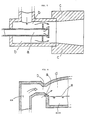
- FIG. 6 A combustion method actually applied to a glass melting furnace is shown in Fig. 6.
- an air supply portion b and a fuel supply portion a are opened into a furnace chamber d, but since there is little clearance between a glass surface 3 and the air supply portion b, gas recirculating currents are not formed in the furnace, and the air current flows along the glass surface 3. Since the fuel is directly injected into the air current, the gas in the furnace is not mixed with the fuel or air, and therefore the combustion at a low oxygen concentration does not occur, to inevitably raise the flame temperature. Thus, NOx emission level is naturally high disadvantageously.
- the object of the present invention is to decrease the NOx generated by the combustion of any fuel in any of various heating furnaces to a level lower than those achieved by conventional combustion methods.
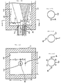
- Figs. 1 stands for a furnace casing, and 2, the interior of the furnace.
- an air supply port 3 and a fuel supply port 4 are opened respectively independently with a distance of l1 kept between them. Furthermore, between said air supply port 3 and a furnace inner wall 5, a distance of l2 is kept.
- air and a fuel are injected into the furnace interior 2, for combustion while recirculating currents are formed as indicated by arrows in Fig. 1 (A). This corresponds to the combustion method stated in claim 1.
- a fuel is injected from a low temperature fuel supply port 6 contained in the air supply port 3, for combustion while the temperature in the furnace interior 2 is lower than the ignition temperature of the fuel, for instance, lower than 750°C, and the combustion method is switched to the combustion method stated in claim 1 when the temperature of the furnace interior 2 reaches the ignition temperature of the fuel, for instance, higher than 750°C.
- the same structure as stated in claim 1 or 2 is adopted except that plural air supply ports 3 are opened into the furnace interior 2, with a distance of l3 kept between the respective air supply ports 1.
- plural fuel supply ports 4 are arranged around the air supply port 3 as shown in Figs. 2.
- the use of one air supply port 3 for one fuel supply port 4 generates a long flame which may be undesirable for some applications.
- the fuel flow rate per fuel supply port 4 decreases, and the flame can be shortened.
- mixing state can be adjusted, to control the length of the flame. If the distance l2 is too short, sufficient recirculating currents cannot be formed in the furnace, and the object of the present invention cannot be achieved. For instance, it is preferable that l2 is not less than 1.5 times the diameter of the air supply port 3.
- the low temperature fuel supply port 6 is provided in the air supply port 3.
- the mixing between air and the fuel starts as soon as the injection into the furnace interior 2 begins, and therefore, the combustion in the furnace takes place stably.
- the temperature in the furnace reaches a high temperature, for instance, higher than 750°C, the combustion can be changed into said regular combustion.
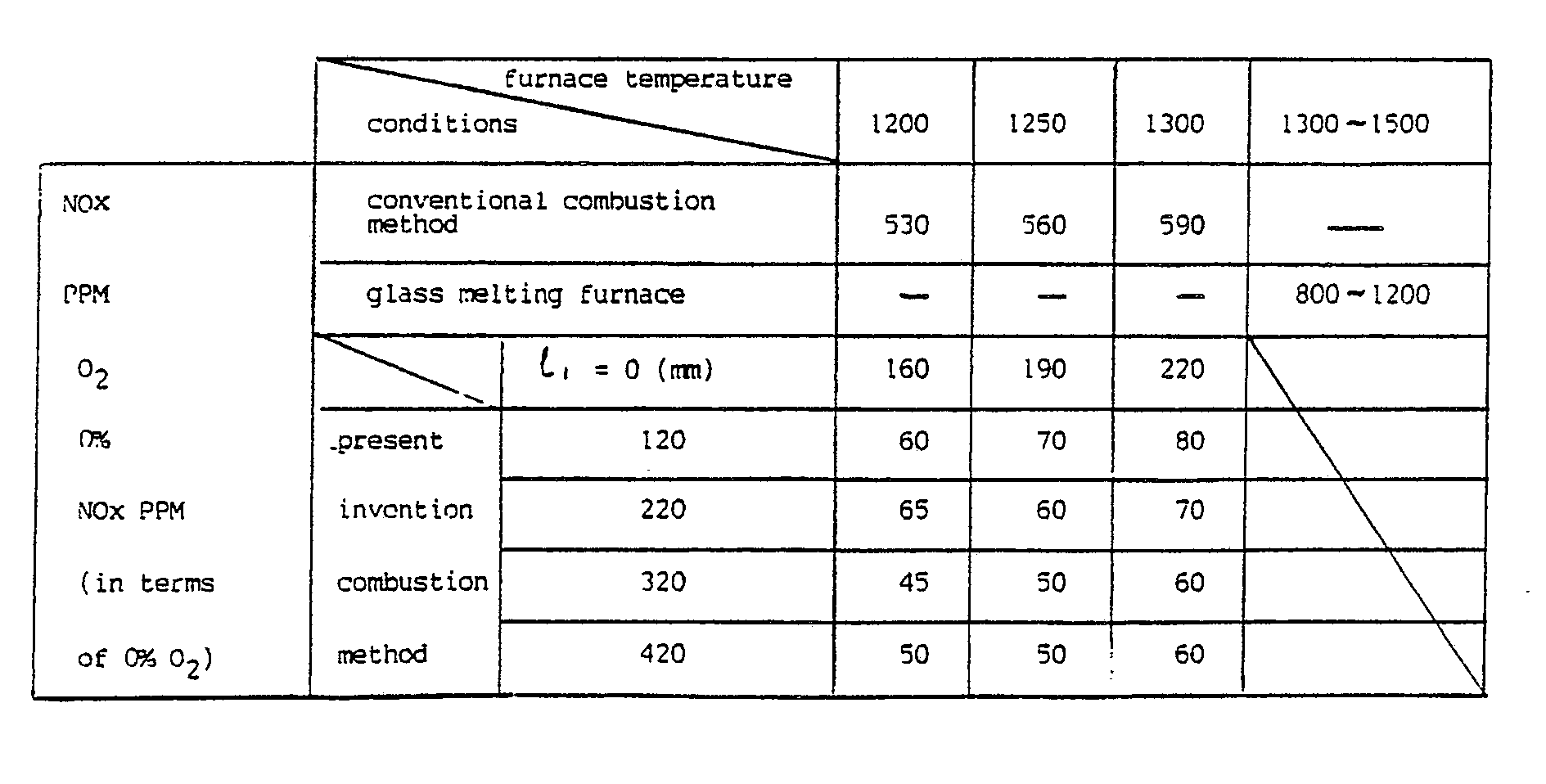
- Fig. 4 shows the data of the following table in a diagram.
Landscapes
- Engineering & Computer Science (AREA)
- Chemical & Material Sciences (AREA)
- Combustion & Propulsion (AREA)
- Mechanical Engineering (AREA)
- General Engineering & Computer Science (AREA)
- Materials Engineering (AREA)
- Organic Chemistry (AREA)
- Combustion Of Fluid Fuel (AREA)
Abstract
Description
- The present invention relates to a furnace combustion method for controlling nitrogen oxides (hereinafter called NOx) mainly used for industrial heating furnaces.
- Conventional combustion methods are described below based on Figs. 5 and 6. In Fig. 5, symbol a stands for a fuel supply portion; and b, an air supply portion. The fuel and air supplied as indicated by arrows from the respective supply portions a and b are mixed in a burner tile c, to burn and generate a flame. In this combustion method, since the area near the base of the flame highest in heat rate and also high in temperature is surrounded by a thermally insulating wall called burner tile c, radial heat dissipation does not occur, and a large volume of NOx is generated by the hot flame disadvantageously.
- A combustion method actually applied to a glass melting furnace is shown in Fig. 6. In this furnace, an air supply portion b and a fuel supply portion a are opened into a furnace chamber d, but since there is little clearance between a
glass surface 3 and the air supply portion b, gas recirculating currents are not formed in the furnace, and the air current flows along theglass surface 3. Since the fuel is directly injected into the air current, the gas in the furnace is not mixed with the fuel or air, and therefore the combustion at a low oxygen concentration does not occur, to inevitably raise the flame temperature. Thus, NOx emission level is naturally high disadvantageously. - The object of the present invention is to decrease the NOx generated by the combustion of any fuel in any of various heating furnaces to a level lower than those achieved by conventional combustion methods.
- In order to explain the invention, reference being made to the accompanying drawing in which
- Figs. 1 (A) and (B) are illustrative sectional views of a furnace to which the present invention method is applied. Fig. 1 (B) is a sectional view at X-X of Fig. 1 (A),
- Figs. 2 are illustrations showing the relation between an air supply port and fuel supply port(s),
- Fig. 3 is an illustration showing the location of adjacent air supply ports,
- Fig. 4 is a NOx level diagram comparing the present invention with a conventional method,
- Fig. 5 and 6 are illustrations of conventional burners.
- In Figs. 1,
symbol 1 stands for a furnace casing, and 2, the interior of the furnace. Into saidfurnace interior 2, anair supply port 3 and afuel supply port 4 are opened respectively independently with a distance of ℓ₁ kept between them. Furthermore, between saidair supply port 3 and a furnaceinner wall 5, a distance of ℓ₂ is kept. In this structure, from saidair supply port 3 and saidfuel supply port 4, air and a fuel are injected into thefurnace interior 2, for combustion while recirculating currents are formed as indicated by arrows in Fig. 1 (A). This corresponds to the combustion method stated inclaim 1. - In the combustion method stated in
claim 2, a fuel is injected from a low temperaturefuel supply port 6 contained in theair supply port 3, for combustion while the temperature in thefurnace interior 2 is lower than the ignition temperature of the fuel, for instance, lower than 750°C, and the combustion method is switched to the combustion method stated inclaim 1 when the temperature of thefurnace interior 2 reaches the ignition temperature of the fuel, for instance, higher than 750°C. In the structure stated inclaim 3, as shown in Fig. 3, the same structure as stated inclaim air supply ports 3 are opened into thefurnace interior 2, with a distance of ℓ₃ kept between the respectiveair supply ports 1. In the structure ofclaim 4, pluralfuel supply ports 4 are arranged around theair supply port 3 as shown in Figs. 2. - In Figs. 1, if air and a fuel are injected separately from the
air supply port 3 and thefuel supply port 4 into thefurnace interior 2, air and the fuel are not mixed directly, but mixed after they have been respectively mixed with the combustion gas in the furnace. As a result, combustion occurs at a low oxygen concentration, to achieve the effect of decreasing NOx. Furthermore, if the air and fuel injection method as stated above is used, the mixing is delayed compared with the mixing of air and fuel in a coaxial injection current as achieved by the conventional burner shown in Fig. 5, and as a result, slow combustion takes place, to provide a low temperature flame free from local high temperature. Also because of this, the effect of decreasing NOx can be achieved. Since the combustion in the present invention is as described above, the use of oneair supply port 3 for onefuel supply port 4 generates a long flame which may be undesirable for some applications. In this case, if pluralfuel supply ports 4 are provided as shown in Figs. 2, the fuel flow rate perfuel supply port 4 decreases, and the flame can be shortened. Even by injecting the fuel not in parallel to the air current, but at any angle against it, or by using afuel supply port 4 with a radial nozzle at the tip, mixing state can be adjusted, to control the length of the flame. If the distance ℓ₂ is too short, sufficient recirculating currents cannot be formed in the furnace, and the object of the present invention cannot be achieved. For instance, it is preferable that ℓ₂ is not less than 1.5 times the diameter of theair supply port 3. - Moreover, depending on the shape and size of the furnace, it is necessary to provide plural
air supply ports 3. In this case, if ℓ₃ is too short, the recirculating currents in the furnace interfere with each other. In this case, if ℓ₃ is not less than 2 times the diameter of theair supply port 3, the mutual interference can be prevented. - In the combustion method of the present invention, since air and a fuel are respectively mixed with the gas in the furnace before combustion, as described before, it is required to raise the temperature in the furnace upto the ignition temperature of the fuel gas by any proper means such as any temperature raising burner or ignition source at the start of operation. In the second version of the present invention, the low temperature
fuel supply port 6 is provided in theair supply port 3. In this case, if the fuel is injected only from the low temperaturefuel supply port 6 contained in theair supply port 3, for combustion, the mixing between air and the fuel starts as soon as the injection into thefurnace interior 2 begins, and therefore, the combustion in the furnace takes place stably. Then, if the temperature in the furnace reaches a high temperature, for instance, higher than 750°C, the combustion can be changed into said regular combustion. - In the present invention, mixing and combustion start in the
furnace interior 2 as described above. Therefore, the area near the base of the flame prone to high heat rate and high temperature is not surrounded by the thermally insulating wall, but exists in the space in the furnace. In thefurnace interior 2, usually materials lower in temperature than the furnaceinner wall 5 such as steel and molten metal exist to be heated. Therefore, as soon as the flame is generated in the space in the furnace, heat radiates to these low temperature materials, to lower the flame temperature. Also in this regard, the effect of lowering the NOx generation level can be achieved. - The following table shows the data obtained by using an experimental furnace shown in Fig. 1, together with the data obtained by the conventional methods. Fig. 4 shows the data of the following table in a diagram. The experimental conditions were as follows:
L₁ = L₂ = 1000 mm
ℓ₂ = 300 mm
Fuel ... Natural gas
Firing rate .... 50 x 10⁴ kcal/h
Air temperature ... 400°C
Air ratio ... 1.2 - From the experimental data, it can be understood that the NOx could be remarkably decreased, compared with the conventional combustion method.
-
- (1) Since air and a fuel are injected directly into the furnace with a distance kept between them and is then mixed, the mixing velocity is low, to cause slow combustion, and as a result, the flame temperature is lowered to generate less NOx.
- (2) Since the distance between the air supply port nearest to the furnace inner wall and the furnace inner wall and the mutual distance between the air support ports are sufficiently long, recirculating currents of combustion gas are formed around the air and fuel supply ports, and before the combustion between air and the fuel starts, the combustion gas is mixed with air and the fuel. Therefore, the combustion occurs at a low oxygen partial pressure. This also lowers the flame temperature, to decrease NOx.
- (3) Since the combustion starts and is completed in the furnace, the heat generation by combustion and the radiation to lower temperature materials take place concurrently to lower the flame temperature, for decreasing NOx.
Claims (6)
- (1) A furnace combustion method, comprising the provision of an air supply port and a fuel supply port respectively independently opened into a furnace with a distance kept between them and with a distance kept between said air supply port and the surrounding furnace wall, wherein combustion air and a fuel are injected respectively from said air supply port and said fuel supply port into the furnace, for combustion with recirculation currents formed in the furnace.
- (2) A furnace combustion method, comprising the provision of an air supply port and a fuel supply port respectively independently opened into a furnace with a distance kept between them, with a distance kept between said air supply port and the surrounding furnace wall, and with a low temperature fuel supply port contained in said air supply port, in order that when the furnace temperature is lower than the ignition temperature of the fuel, combustion air may be injected from said air supply port while the fuel may be injected only from said low temperature fuel supply port, for combustion, and that when the furnace temperature has reached a temperature higher than the ignition temperature of the fuel, the supply of fuel from said low temperature fuel supply port may be stopped, while the fuel may be injected from the other fuel supply port, for combustion in the furnace with recirculating currents formed in the furnace.
- (3) A furnace combustion method, according to claim 1 or 2, wherein plural air supply ports apart from each other are opened into the furnace.
- (4) A furnace combustion method, according to claim 1 or 2, wherein plural fuel supply ports are arranged around the air supply port.
- (5) A furnace for carrying out a method according to claim 1, comprising an air supply port and a fuel supply port respectively independently opened into a furnace with a distance kept between said air supply port and the surrouding furnace wall.
- (6) A furnace according to claim 5, characterized in that it has a construction to carry out a method according to claims 2-4.
Applications Claiming Priority (2)
| Application Number | Priority Date | Filing Date | Title |
|---|---|---|---|
| JP127979/88 | 1988-05-25 | ||
| JP63127979A JP2683545B2 (en) | 1988-05-25 | 1988-05-25 | Combustion method in furnace |
Publications (3)
| Publication Number | Publication Date |
|---|---|
| EP0343746A2 true EP0343746A2 (en) | 1989-11-29 |
| EP0343746A3 EP0343746A3 (en) | 1990-10-24 |
| EP0343746B1 EP0343746B1 (en) | 1994-03-09 |
Family
ID=14973432
Family Applications (1)
| Application Number | Title | Priority Date | Filing Date |
|---|---|---|---|
| EP89201313A Expired - Lifetime EP0343746B1 (en) | 1988-05-25 | 1989-05-23 | A furnace combustion method |
Country Status (4)
| Country | Link |
|---|---|
| US (1) | US4945841A (en) |
| EP (1) | EP0343746B1 (en) |
| JP (1) | JP2683545B2 (en) |
| DE (1) | DE68913590T2 (en) |
Cited By (15)
| Publication number | Priority date | Publication date | Assignee | Title |
|---|---|---|---|---|
| EP0413309A3 (en) * | 1989-08-15 | 1991-06-05 | Union Carbide Industrial Gases Technology Corporation | Reduced nox combustion method |
| EP0507995A3 (en) * | 1991-04-12 | 1993-02-03 | Union Carbide Ind Gases Tech | Segregated zoning combustion |
| US5570679A (en) * | 1994-06-02 | 1996-11-05 | Wunning; Joachim | Industrial burner with low NOx emissions |
| WO1996037734A1 (en) * | 1995-05-26 | 1996-11-28 | Canadian Gas Research Institute | LOW NOx BURNER |
| EP0756135A1 (en) * | 1995-07-27 | 1997-01-29 | Tokyo Gas Company Limited | A low nitrogen oxide producing burner system and burning method |
| WO2000037852A1 (en) * | 1998-12-21 | 2000-06-29 | Alstom Power Inc. | A firing system for ethylene cracking furnaces |
| WO2001072908A1 (en) * | 2000-03-29 | 2001-10-04 | Mitsubishi Chemical Corporation | Method and apparatus for producing carbon black, and method and apparatus for burning in furnace |
| WO2006031163A1 (en) * | 2004-09-15 | 2006-03-23 | Aga Ab | A method pertaining to combustion, and a burner |
| WO2006133880A1 (en) | 2005-06-14 | 2006-12-21 | G. Kromschröder AG | Burner arrangement and operating method thereof |
| EP1729062A3 (en) * | 2005-06-02 | 2007-10-03 | Air Products and Chemicals, Inc. | Dynamic burner reconfiguration and combustion system for process heaters and boilers |
| WO2008152335A2 (en) | 2007-06-08 | 2008-12-18 | Saint-Gobain Emballage | Diluted combustion |
| CN102401394A (en) * | 2010-09-09 | 2012-04-04 | 中外炉工业株式会社 | Heat accumulating type combustion device and heating furnace |
| EP2442026A1 (en) | 2010-10-15 | 2012-04-18 | Elster GmbH | High temperature burner for burner operating methods with two operational states |
| WO2012002829A3 (en) * | 2010-07-02 | 2013-08-22 | Ics Industrial Combustion Systems | The method for burning fuel in combustion chambers of metallurgical furnaces, steelmaking furnaces, heating boilers and power boilers and fuel burning system in combustion chambers of metallurgical furnaces, steelmaking furnaces, heating boilers and power boilers |
| US9995481B2 (en) | 2011-12-20 | 2018-06-12 | Eclipse, Inc. | Method and apparatus for a dual mode burner yielding low NOx emission |
Families Citing this family (43)
| Publication number | Priority date | Publication date | Assignee | Title |
|---|---|---|---|---|
| US4946382A (en) * | 1989-05-23 | 1990-08-07 | Union Carbide Corporation | Method for combusting fuel containing bound nitrogen |
| JPH05180410A (en) * | 1991-12-30 | 1993-07-23 | Tokyo Gas Co Ltd | Low NOx combustion method in high temperature furnace |
| US5730591A (en) * | 1993-04-12 | 1998-03-24 | North American Manufacturing Company | Method and apparatus for aggregate treatment |
| US5407345A (en) * | 1993-04-12 | 1995-04-18 | North American Manufacturing Co. | Ultra low NOX burner |
| US5667376A (en) * | 1993-04-12 | 1997-09-16 | North American Manufacturing Company | Ultra low NOX burner |
| JP3052262B2 (en) * | 1994-08-04 | 2000-06-12 | 株式会社神戸製鋼所 | Combustion furnace and its low NOx combustion method |
| US5931653A (en) * | 1995-07-24 | 1999-08-03 | Tokyo Gas Co., Ltd. | Low nitrogen oxide burner and burning method |
| JPH09137916A (en) | 1995-11-16 | 1997-05-27 | Tokyo Gas Co Ltd | Nitrogen oxide low generation combustion method and apparatus |
| JP3557028B2 (en) * | 1996-02-14 | 2004-08-25 | Jfeスチール株式会社 | Combustion burner and combustion method in furnace |
| US5813846A (en) * | 1997-04-02 | 1998-09-29 | North American Manufacturing Company | Low NOx flat flame burner |
| US6206686B1 (en) | 1998-05-01 | 2001-03-27 | North American Manufacturing Company | Integral low NOx injection burner |
| US6062848A (en) * | 1998-05-29 | 2000-05-16 | Coen Company, Inc. | Vibration-resistant low NOx burner |
| US6793486B2 (en) * | 1998-07-30 | 2004-09-21 | Bloom Engineering Company, Inc. | Burner for non-symmetrical combustion and method |
| ATE276482T1 (en) * | 1998-07-30 | 2004-10-15 | Bloom Eng Co Inc | BURNER FOR NON-SYMMETRIC COMBUSTION AND METHOD THEREOF |
| US6113386A (en) * | 1998-10-09 | 2000-09-05 | North American Manufacturing Company | Method and apparatus for uniformly heating a furnace |
| US6672862B2 (en) | 2000-03-24 | 2004-01-06 | North American Manufacturing Company | Premix burner with integral mixers and supplementary burner system |
| JP4904629B2 (en) * | 2000-03-29 | 2012-03-28 | 三菱化学株式会社 | Carbon black manufacturing apparatus and manufacturing method, furnace combustion apparatus and furnace combustion method |
| US7175423B1 (en) | 2000-10-26 | 2007-02-13 | Bloom Engineering Company, Inc. | Air staged low-NOx burner |
| US6616442B2 (en) | 2000-11-30 | 2003-09-09 | John Zink Company, Llc | Low NOx premix burner apparatus and methods |
| US6652265B2 (en) | 2000-12-06 | 2003-11-25 | North American Manufacturing Company | Burner apparatus and method |
| US6565361B2 (en) | 2001-06-25 | 2003-05-20 | John Zink Company, Llc | Methods and apparatus for burning fuel with low NOx formation |
| US6929469B2 (en) * | 2002-02-28 | 2005-08-16 | North American Manufacturing Company | Burner apparatus |
| US6824383B2 (en) * | 2002-08-08 | 2004-11-30 | North American Manufacturing Company | Diffuse combustion method and apparatus |
| US6638061B1 (en) | 2002-08-13 | 2003-10-28 | North American Manufacturing Company | Low NOx combustion method and apparatus |
| GB2394275B (en) * | 2002-08-14 | 2005-09-21 | Hamworthy Combustion Eng Ltd | Burner and method of burning gas in a furnace |
| US6979191B1 (en) | 2004-06-17 | 2005-12-27 | Zeeco, Inc. | Combustion apparatus and method for radiating wall heating system |
| FR2880410B1 (en) * | 2005-01-03 | 2007-03-16 | Air Liquide | STEAM COMBUSTION METHOD PRODUCING ASYMMETRIC FLAMES |
| US20060246388A1 (en) * | 2005-04-29 | 2006-11-02 | Hauck Manufacturing Company | Reduced NOx method of combustion |
| ITMI20060155A1 (en) * | 2006-01-31 | 2007-08-01 | Techint Spa | FLAME BURNER WITH FLAT LOW EMISSIONS POLLUTANT |
| US8696348B2 (en) * | 2006-04-26 | 2014-04-15 | Air Products And Chemicals, Inc. | Ultra-low NOx burner assembly |
| SE531788C2 (en) * | 2006-06-22 | 2009-08-04 | Aga Ab | Procedure for combustion with oxygen, and burner |
| US20080081301A1 (en) * | 2006-10-03 | 2008-04-03 | Hannum Mark C | Low NOx combustion |
| US8083517B2 (en) * | 2008-03-28 | 2011-12-27 | Fives North American Combustion, Inc. | Method of operating a furnace |
| US20100233639A1 (en) * | 2009-03-11 | 2010-09-16 | Richardson Andrew P | Burner for reducing wall wear in a melter |
| US8202470B2 (en) * | 2009-03-24 | 2012-06-19 | Fives North American Combustion, Inc. | Low NOx fuel injection for an indurating furnace |
| US8545213B2 (en) * | 2010-03-09 | 2013-10-01 | Air Products And Chemicals, Inc. | Reformer and method of operating the reformer |
| US8827691B2 (en) * | 2010-07-12 | 2014-09-09 | L'air Liquide, Societe Anonyme Pour L'etude Et L'exploitation Des Procedes Georges Claude | Distributed combustion process and burner |
| EP2479492A1 (en) * | 2011-01-21 | 2012-07-25 | Technip France | Burner, furnace |
| US9909755B2 (en) | 2013-03-15 | 2018-03-06 | Fives North American Combustion, Inc. | Low NOx combustion method and apparatus |
| JP6289020B2 (en) * | 2013-10-18 | 2018-03-07 | 大阪瓦斯株式会社 | heating furnace |
| US9593847B1 (en) | 2014-03-05 | 2017-03-14 | Zeeco, Inc. | Fuel-flexible burner apparatus and method for fired heaters |
| US9593848B2 (en) | 2014-06-09 | 2017-03-14 | Zeeco, Inc. | Non-symmetrical low NOx burner apparatus and method |
| US11754282B2 (en) | 2021-06-23 | 2023-09-12 | Zeeco, Inc. | Lean pre-mix radiant wall burner apparatus and method |
Family Cites Families (15)
| Publication number | Priority date | Publication date | Assignee | Title |
|---|---|---|---|---|
| GB1215925A (en) * | 1967-02-03 | 1970-12-16 | Gas Council | Fuel gas/oxygen burner |
| DE2303280C2 (en) * | 1973-01-24 | 1982-07-29 | Robert von Dipl.-Ing. 8032 Gräfelfing Linde | Burners for flowable fuels |
| US4035137A (en) * | 1973-04-26 | 1977-07-12 | Forney Engineering Company | Burner unit |
| GB1487385A (en) * | 1974-07-26 | 1977-09-28 | British Steel Corp | Furnace heating |
| JPS5261545U (en) * | 1975-10-31 | 1977-05-06 | ||
| US4496306A (en) * | 1978-06-09 | 1985-01-29 | Hitachi Shipbuilding & Engineering Co., Ltd. | Multi-stage combustion method for inhibiting formation of nitrogen oxides |
| US4395223A (en) * | 1978-06-09 | 1983-07-26 | Hitachi Shipbuilding & Engineering Co., Ltd. | Multi-stage combustion method for inhibiting formation of nitrogen oxides |
| JPS5819929B2 (en) * | 1978-07-11 | 1983-04-20 | 新日本製鐵株式会社 | Low NO↓x burner |
| JPS5551447U (en) * | 1978-09-27 | 1980-04-04 | ||
| US4378205A (en) * | 1980-04-10 | 1983-03-29 | Union Carbide Corporation | Oxygen aspirator burner and process for firing a furnace |
| GB2076135B (en) * | 1980-04-22 | 1984-04-18 | Mitsubishi Heavy Ind Ltd | Pulverized fuel firing apparatus |
| US4505666A (en) * | 1981-09-28 | 1985-03-19 | John Zink Company | Staged fuel and air for low NOx burner |
| DE3202105C2 (en) * | 1982-01-23 | 1985-08-08 | Karl-Heinz 5600 Wuppertal Frickel | Burners, in particular for glass melting furnaces |
| FR2532405A1 (en) * | 1982-08-25 | 1984-03-02 | Air Liquide | METHOD AND DEVICE FOR ELECTRICALLY IGNITING AN OXYCOMBUSTIBLE BURNER |
| JPH082005A (en) * | 1994-06-15 | 1996-01-09 | Nec Corp | Ink jet printer |
-
1988
- 1988-05-25 JP JP63127979A patent/JP2683545B2/en not_active Expired - Lifetime
-
1989
- 1989-05-18 US US07/353,822 patent/US4945841A/en not_active Expired - Lifetime
- 1989-05-23 DE DE68913590T patent/DE68913590T2/en not_active Expired - Lifetime
- 1989-05-23 EP EP89201313A patent/EP0343746B1/en not_active Expired - Lifetime
Cited By (23)
| Publication number | Priority date | Publication date | Assignee | Title |
|---|---|---|---|---|
| EP0413309A3 (en) * | 1989-08-15 | 1991-06-05 | Union Carbide Industrial Gases Technology Corporation | Reduced nox combustion method |
| EP0507995A3 (en) * | 1991-04-12 | 1993-02-03 | Union Carbide Ind Gases Tech | Segregated zoning combustion |
| US5570679A (en) * | 1994-06-02 | 1996-11-05 | Wunning; Joachim | Industrial burner with low NOx emissions |
| WO1996037734A1 (en) * | 1995-05-26 | 1996-11-28 | Canadian Gas Research Institute | LOW NOx BURNER |
| US5772421A (en) * | 1995-05-26 | 1998-06-30 | Canadian Gas Research Institute | Low nox burner |
| EP0756135A1 (en) * | 1995-07-27 | 1997-01-29 | Tokyo Gas Company Limited | A low nitrogen oxide producing burner system and burning method |
| WO2000037852A1 (en) * | 1998-12-21 | 2000-06-29 | Alstom Power Inc. | A firing system for ethylene cracking furnaces |
| WO2001072908A1 (en) * | 2000-03-29 | 2001-10-04 | Mitsubishi Chemical Corporation | Method and apparatus for producing carbon black, and method and apparatus for burning in furnace |
| WO2006031163A1 (en) * | 2004-09-15 | 2006-03-23 | Aga Ab | A method pertaining to combustion, and a burner |
| US7594811B2 (en) | 2004-09-15 | 2009-09-29 | Aga Ab | Method pertaining to combustion, and a burner |
| EP1729062A3 (en) * | 2005-06-02 | 2007-10-03 | Air Products and Chemicals, Inc. | Dynamic burner reconfiguration and combustion system for process heaters and boilers |
| WO2006133880A1 (en) | 2005-06-14 | 2006-12-21 | G. Kromschröder AG | Burner arrangement and operating method thereof |
| WO2008152335A2 (en) | 2007-06-08 | 2008-12-18 | Saint-Gobain Emballage | Diluted combustion |
| WO2008152335A3 (en) * | 2007-06-08 | 2009-05-28 | Saint Gobain Emballage | Diluted combustion |
| EA016134B1 (en) * | 2007-06-08 | 2012-02-28 | Сэн-Гобэн Амбаллаж | Weakened burn |
| CN101802497B (en) * | 2007-06-08 | 2012-09-05 | 圣戈班昂巴拉热公司 | Diluted combustion |
| US9188333B2 (en) | 2007-06-08 | 2015-11-17 | Saint-Gobain Emballage | Dilute combustion |
| WO2012002829A3 (en) * | 2010-07-02 | 2013-08-22 | Ics Industrial Combustion Systems | The method for burning fuel in combustion chambers of metallurgical furnaces, steelmaking furnaces, heating boilers and power boilers and fuel burning system in combustion chambers of metallurgical furnaces, steelmaking furnaces, heating boilers and power boilers |
| CN102401394A (en) * | 2010-09-09 | 2012-04-04 | 中外炉工业株式会社 | Heat accumulating type combustion device and heating furnace |
| CN102401394B (en) * | 2010-09-09 | 2016-03-16 | 中外炉工业株式会社 | Heat accumulating burner capable and heating furnace |
| EP2442026A1 (en) | 2010-10-15 | 2012-04-18 | Elster GmbH | High temperature burner for burner operating methods with two operational states |
| WO2012048954A1 (en) | 2010-10-15 | 2012-04-19 | Elster Gmbh | High-temperature burner for burner operating methods having two operational states |
| US9995481B2 (en) | 2011-12-20 | 2018-06-12 | Eclipse, Inc. | Method and apparatus for a dual mode burner yielding low NOx emission |
Also Published As
| Publication number | Publication date |
|---|---|
| EP0343746A3 (en) | 1990-10-24 |
| JPH01300103A (en) | 1989-12-04 |
| EP0343746B1 (en) | 1994-03-09 |
| US4945841A (en) | 1990-08-07 |
| DE68913590T2 (en) | 1994-06-16 |
| DE68913590D1 (en) | 1994-04-14 |
| JP2683545B2 (en) | 1997-12-03 |
Similar Documents
| Publication | Publication Date | Title |
|---|---|---|
| EP0343746A2 (en) | A furnace combustion method | |
| KR100830300B1 (en) | Tubular flame burner | |
| EP0772001B1 (en) | LOW NOx BURNER | |
| CA2070971C (en) | Air-cooled oxygen gas burner assembly | |
| US3730668A (en) | Combustion method of gas burners for suppressing the formation of nitrogen oxides and burner apparatus for practicing said method | |
| EP0762050A2 (en) | Low-NOx staged combustion device for controlled radiative heating in high temperature furnaces | |
| JPH11311403A (en) | Heating method of treatment object matter in heating furnace | |
| BR0208586B1 (en) | combustion method comprising separate fuel and oxidant injections and mounting burner. | |
| US6461145B1 (en) | Flat flame burners | |
| US4309165A (en) | High velocity combustion furnace and burner | |
| KR101729201B1 (en) | Oxy fuel burner | |
| CN109442402A (en) | A kind of water cooling premixed combustion method and device | |
| JP3176786B2 (en) | Oxygen burner | |
| EP3441670A1 (en) | Method and burner assembly for combusting a fuel gas with an oxidant | |
| JPH06330184A (en) | Heat treatment equipment | |
| JPH07103428A (en) | Oxygen burner | |
| KR200210603Y1 (en) | a combustor of uniform temperature distribution using free recirculation | |
| JPH0125870Y2 (en) | ||
| JP3590495B2 (en) | Low NOx burner for high temperature air | |
| JPS5817364B2 (en) | Low NOx radiant tube burner | |
| JP2678505B2 (en) | Low NOx burner | |
| JP2003279255A (en) | Rotary hearth furnace and operating method thereof | |
| JPS6238089Y2 (en) | ||
| JPS61264125A (en) | Partial premixing combustion method | |
| JPS6039603Y2 (en) | Multistage combustion type nitrogen oxide suppression burner |
Legal Events
| Date | Code | Title | Description |
|---|---|---|---|
| PUAI | Public reference made under article 153(3) epc to a published international application that has entered the european phase |
Free format text: ORIGINAL CODE: 0009012 |
|
| AK | Designated contracting states |
Kind code of ref document: A2 Designated state(s): AT BE CH DE ES FR GB GR IT LI LU NL SE |
|
| RBV | Designated contracting states (corrected) |
Designated state(s): DE FR GB |
|
| PUAL | Search report despatched |
Free format text: ORIGINAL CODE: 0009013 |
|
| AK | Designated contracting states |
Kind code of ref document: A3 Designated state(s): AT BE CH DE ES FR GB GR IT LI LU NL SE |
|
| 17P | Request for examination filed |
Effective date: 19910422 |
|
| 17Q | First examination report despatched |
Effective date: 19920206 |
|
| GRAA | (expected) grant |
Free format text: ORIGINAL CODE: 0009210 |
|
| AK | Designated contracting states |
Kind code of ref document: B1 Designated state(s): DE FR GB |
|
| REF | Corresponds to: |
Ref document number: 68913590 Country of ref document: DE Date of ref document: 19940414 |
|
| ET | Fr: translation filed | ||
| PLBE | No opposition filed within time limit |
Free format text: ORIGINAL CODE: 0009261 |
|
| STAA | Information on the status of an ep patent application or granted ep patent |
Free format text: STATUS: NO OPPOSITION FILED WITHIN TIME LIMIT |
|
| 26N | No opposition filed | ||
| REG | Reference to a national code |
Ref country code: GB Ref legal event code: IF02 |
|
| PGFP | Annual fee paid to national office [announced via postgrant information from national office to epo] |
Ref country code: DE Payment date: 20080529 Year of fee payment: 20 |
|
| PGFP | Annual fee paid to national office [announced via postgrant information from national office to epo] |
Ref country code: GB Payment date: 20080528 Year of fee payment: 20 |
|
| REG | Reference to a national code |
Ref country code: GB Ref legal event code: PE20 Expiry date: 20090522 |
|
| PG25 | Lapsed in a contracting state [announced via postgrant information from national office to epo] |
Ref country code: GB Free format text: LAPSE BECAUSE OF EXPIRATION OF PROTECTION Effective date: 20090522 |
|
| PGFP | Annual fee paid to national office [announced via postgrant information from national office to epo] |
Ref country code: FR Payment date: 20080514 Year of fee payment: 20 |