EP0343587B1 - Dispositif de mesure de l'énergie d'un arc électrique - Google Patents
Dispositif de mesure de l'énergie d'un arc électrique Download PDFInfo
- Publication number
- EP0343587B1 EP0343587B1 EP89109234A EP89109234A EP0343587B1 EP 0343587 B1 EP0343587 B1 EP 0343587B1 EP 89109234 A EP89109234 A EP 89109234A EP 89109234 A EP89109234 A EP 89109234A EP 0343587 B1 EP0343587 B1 EP 0343587B1
- Authority
- EP
- European Patent Office
- Prior art keywords
- optical fiber
- support
- arc
- electrode
- energy
- Prior art date
- Legal status (The legal status is an assumption and is not a legal conclusion. Google has not performed a legal analysis and makes no representation as to the accuracy of the status listed.)
- Expired - Lifetime
Links
- 239000013307 optical fiber Substances 0.000 claims description 26
- 238000010891 electric arc Methods 0.000 claims description 6
- 229920000491 Polyphenylsulfone Polymers 0.000 claims description 5
- 239000000463 material Substances 0.000 claims description 3
- 230000003287 optical effect Effects 0.000 claims description 2
- 239000000835 fiber Substances 0.000 description 9
- 238000005259 measurement Methods 0.000 description 3
- 210000000056 organ Anatomy 0.000 description 3
- 230000003321 amplification Effects 0.000 description 1
- 238000004458 analytical method Methods 0.000 description 1
- 230000006378 damage Effects 0.000 description 1
- 230000006866 deterioration Effects 0.000 description 1
- 238000010438 heat treatment Methods 0.000 description 1
- 238000003199 nucleic acid amplification method Methods 0.000 description 1
- 230000005855 radiation Effects 0.000 description 1
Images


Classifications
-
- G—PHYSICS
- G01—MEASURING; TESTING
- G01J—MEASUREMENT OF INTENSITY, VELOCITY, SPECTRAL CONTENT, POLARISATION, PHASE OR PULSE CHARACTERISTICS OF INFRARED, VISIBLE OR ULTRAVIOLET LIGHT; COLORIMETRY; RADIATION PYROMETRY
- G01J1/00—Photometry, e.g. photographic exposure meter
- G01J1/42—Photometry, e.g. photographic exposure meter using electric radiation detectors
-
- G—PHYSICS
- G01—MEASURING; TESTING
- G01J—MEASUREMENT OF INTENSITY, VELOCITY, SPECTRAL CONTENT, POLARISATION, PHASE OR PULSE CHARACTERISTICS OF INFRARED, VISIBLE OR ULTRAVIOLET LIGHT; COLORIMETRY; RADIATION PYROMETRY
- G01J1/00—Photometry, e.g. photographic exposure meter
- G01J1/02—Details
- G01J1/04—Optical or mechanical part supplementary adjustable parts
-
- G—PHYSICS
- G01—MEASURING; TESTING
- G01J—MEASUREMENT OF INTENSITY, VELOCITY, SPECTRAL CONTENT, POLARISATION, PHASE OR PULSE CHARACTERISTICS OF INFRARED, VISIBLE OR ULTRAVIOLET LIGHT; COLORIMETRY; RADIATION PYROMETRY
- G01J1/00—Photometry, e.g. photographic exposure meter
- G01J1/02—Details
- G01J1/04—Optical or mechanical part supplementary adjustable parts
- G01J1/0407—Optical elements not provided otherwise, e.g. manifolds, windows, holograms, gratings
- G01J1/0425—Optical elements not provided otherwise, e.g. manifolds, windows, holograms, gratings using optical fibers
-
- H—ELECTRICITY
- H05—ELECTRIC TECHNIQUES NOT OTHERWISE PROVIDED FOR
- H05H—PLASMA TECHNIQUE; PRODUCTION OF ACCELERATED ELECTRICALLY-CHARGED PARTICLES OR OF NEUTRONS; PRODUCTION OR ACCELERATION OF NEUTRAL MOLECULAR OR ATOMIC BEAMS
- H05H1/00—Generating plasma; Handling plasma
- H05H1/0006—Investigating plasma, e.g. measuring the degree of ionisation or the electron temperature
- H05H1/0012—Investigating plasma, e.g. measuring the degree of ionisation or the electron temperature using electromagnetic or particle radiation, e.g. interferometry
- H05H1/0025—Investigating plasma, e.g. measuring the degree of ionisation or the electron temperature using electromagnetic or particle radiation, e.g. interferometry by using photoelectric means
-
- H—ELECTRICITY
- H05—ELECTRIC TECHNIQUES NOT OTHERWISE PROVIDED FOR
- H05H—PLASMA TECHNIQUE; PRODUCTION OF ACCELERATED ELECTRICALLY-CHARGED PARTICLES OR OF NEUTRONS; PRODUCTION OR ACCELERATION OF NEUTRAL MOLECULAR OR ATOMIC BEAMS
- H05H1/00—Generating plasma; Handling plasma
- H05H1/24—Generating plasma
- H05H1/26—Plasma torches
- H05H1/32—Plasma torches using an arc
- H05H1/34—Details, e.g. electrodes, nozzles
- H05H1/3494—Means for controlling discharge parameters
-
- G—PHYSICS
- G01—MEASURING; TESTING
- G01J—MEASUREMENT OF INTENSITY, VELOCITY, SPECTRAL CONTENT, POLARISATION, PHASE OR PULSE CHARACTERISTICS OF INFRARED, VISIBLE OR ULTRAVIOLET LIGHT; COLORIMETRY; RADIATION PYROMETRY
- G01J1/00—Photometry, e.g. photographic exposure meter
- G01J1/42—Photometry, e.g. photographic exposure meter using electric radiation detectors
- G01J1/429—Photometry, e.g. photographic exposure meter using electric radiation detectors applied to measurement of ultraviolet light
Definitions
- the present invention relates to a device for measuring the energy of an electric arc released in the form of light, ultraviolet or infrared radiation.
- the present invention aims to allow a precise and instantaneous measurement of the energy of an electric arc, using a simple and inexpensive apparatus to replace in the event of its deterioration by the heat of the arc.
- Figure 1 shows in elevation seen from the front an optical fiber support around an anode electrode.
- FIG. 2 shows the optical fiber support in section along the axis II-II of Figure 1 and the electrode.
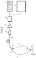
- Figure 3 shows the entire device.
- FIG. 4 represents the auxiliary organs of the electronic energy measurement and analysis organ.
- the support 1 of the optical fibers in the vicinity of the arc is fixed to the electrode 2 by means of the nut 11, screwed onto the thread 3 of the electrode.
- the support rests by its edge on the head of the nut, it is snapped by its shoulder 8 on flexible pawls 9 of the edge of the nut.
- the fiber support and the nut are made of a plastic material of sufficient dielectric strength not to disturb the arc, such as a polyphenylsulfone.
- the optical fibers such as 10 are arranged in grooves 4, 5, 6, 7 at 90 ° from each other, inclined at 45 ° relative to the axis of the electrode; they are stripped of their sheath in the immediate vicinity of the tip of the electrode, in a manner not shown. Their ends are a few millimeters from the arc.
- FIG. 3 represents the entire device during operation.
- the arc 14 springs between the anode 2 and the cathode 13 connected to the ground.
- the optical fibers of which only two 10 and 12 have been shown, reach connectors 15, 16. From these, optical fibers gathered in a cable 17 join a photoelectric cell 18.
- the distance from this cell to the electrode is of the order of 5 to 10 meters.
- the electric current supplied by this cell, after amplification in the amplifier 19, is transmitted to a recording device 20 with an electronic card, which analyzes the energy received by the cell.
- the recorder 20 is connected on the one hand to a display element 21, on the other hand to a printer 22 making it possible to record the energies of successive arc discharges.
- the electronic measuring device 20 is powered by rechargeable batteries 24 as shown in FIG. 4. These are connected to a voltage controller 25 and a power supply from the sector 26, for recharging them outside the periods of operation of the arc.
- the printer 22 is connected to the measuring member 20 by an interface 23.
Landscapes
- Physics & Mathematics (AREA)
- Spectroscopy & Molecular Physics (AREA)
- General Physics & Mathematics (AREA)
- Plasma & Fusion (AREA)
- Engineering & Computer Science (AREA)
- Toxicology (AREA)
- General Health & Medical Sciences (AREA)
- Electromagnetism (AREA)
- Health & Medical Sciences (AREA)
- Photometry And Measurement Of Optical Pulse Characteristics (AREA)
- Testing Relating To Insulation (AREA)
- Measurement And Recording Of Electrical Phenomena And Electrical Characteristics Of The Living Body (AREA)
- Arc Welding Control (AREA)
Description
- La présente invention concerne un dispositif de mesure de l'énergie d'un arc électrique dégagée sous forme de rayonnements lumineux, ultra-violet ou infra-rouge.
- On sait actuellement très mal mesurer l'énergie instantanée dégagée dans un arc électrique par des mesures électriques, car il est difficile de séparer l'énergie consommée par l'arc de celle consommée par l'échauffement des électrodes.
- La présente invention a pour but de permettre une mesure précise et instantanée de l'énergie d'un arc électrique, à l'aide d'un appareillage simple et peu coûteux à remplacer en cas de sa détérioration par la chaleur de l'arc.
- Le dispositif de mesure selon l'invention est caractérisé en ce qu'il comprend
- a) un support d'au moins un fibre optique disposé sur la tête d'une électrode de l'arc, en une matière plastique d'une rigidité diélectrique suffisante pour ne pas perturber le fonctionnement de l'arc,
- - b) au moins un fibre optique assujettie sur ce support et d'extrémité arrivant à proximité de la pointe de l'électrode,
- - c) un connecteur optique recevant d'une part l'autre extrémité de la fibre optique, d'autre part une extrémité d'un câble à fibres optiques de liaison avec une cellule photo-électrique,
- - d) une cellule photo-électrique disposée à une distance de l'électrode suffisante pour être à l'abri des perturbations dues à celle-ci,
- - e) un organe électronique relié à la cellule photo-électrique et enregistrant et affichant l'énergie dégagée par l'arc.
- Il répond en outre de préférence à au moins l'une des caractéristiques suivantes :
- Le support de la fibre optique est fixé à l'électrode par encliquetage sur l'extrémité d'un écrou vissé sur le pourtour fileté de l'électrode.
- Le support de la fibre optique est percé d'au moins une rainure de logement de la fibre optique.
- Il comprend plusieurs fibres optiques réparties régulièrement sur le pourtour du support.
- Le support de la fibre optique est en polyphénylsulfone.
- L'écrou de fixation du support est également en polyphénylsulfone.
- L'organe électronique d'enregistrement est relié à une imprimante.
- Il est décrit ci-après, à titre d'exemple et en référence aux figures du dessin annexé, un dispositif de mesure de l'énergie d'un arc électrique selon l'invention.
- La figure 1 représente en élévation vu de face un support de fibres optiques autour d'une électrode formant anode.
- La figure 2 représente le support de fibres optiques en coupe selon l'axe II-II de la figure 1 et l'électrode.
- La figure 3 représente l'ensemble du dispositif.
- La figure 4 représente les organes auxiliaires de l'organe électronique de mesure et d'analyse de l'énergie.
- Dans les figures 1 et 2, le support 1 des fibres optiques au voisinage de l'arc est fixé à l'électrode 2 par l'intermédiaire de l'écrou 11, vissé sur le filetage 3 de l'électrode.
- Le support repose par son bord sur la tête de l'écrou, il est encliqueté par son épaulement 8 sur des cliquets souples 9 du bord de l'écrou. Le support des fibres et l'écrou sont en une matière plastique de rigidité diélectrique suffisante pour ne pas perturber l'arc, telle qu'un polyphénylsulfone. Les fibres optiques telles que 10 sont disposées dans des rainures 4, 5, 6, 7 à 90° les unes des autres, inclinées à 45° par rapport à l'axe de l'électrode ; elles sont dénudées de leur gaine à proximité immédiate de la pointe de l'électrode, de manière non représentée. Leurs extrémités sont à quelques millimètres de l'arc.
- La figure 3 représente l'ensemble du dispositif en cours de fonctionnement. L'arc 14 jaillit entre l'anode 2 et la cathode 13 reliée à la terre. Les fibres optiques, dont seules deux 10 et 12 ont été représentées, parviennent à des connecteurs 15, 16. A partir de ceux-ci des fibres optiques rassemblées dans un câble 17 rejoignent une cellule photo-électrique 18. La distance de cette cellule à l'électrode est de l'ordre de 5 à 10 mètres. Le courant électrique fourni par cette cellule, après amplification dans l'amplificateur 19, est transmis à un appareil enregistreur 20 à carte électronique, qui analyse l'énergie reçue par la cellule. L'enregistreur 20 est relié d'une part à un élément d'affichage 21, d'autre part à une imprimante 22 permettant d'enregistrer les énergies de décharges d'arc successives.
- En cas de destruction par l'arc de l'extrémité des fibres optiques sur le support 1, il suffit de remplacer la ou les fibres optiques détruites à partir du ou des connecteurs correspondants.
- Afin de mettre à l'abri le dispositif de mesure des perturbations du réseau induites par la décharge de l'arc, l'organe électronique de mesure 20 est alimenté par des accumulateurs rechargeables 24 comme représenté en figure 4. Ceux-ci sont reliés à un contrôleur de tension 25 et à une alimentation par le secteur 26, pour leur recharge en dehors des périodes de fonctionnement de l'arc.
- L'imprimante 22 est reliée à l'organe de mesure 20 par une interface 23.
Claims (7)
et e) un organe électronique (20) relié à la cellule photo-électrique et enregistrant et affichant l'énergie dégagée par l'arc.
Applications Claiming Priority (2)
| Application Number | Priority Date | Filing Date | Title |
|---|---|---|---|
| FR8806877A FR2632066B1 (fr) | 1988-05-24 | 1988-05-24 | Disp ositif de mesure de l'energie d'un arc electrique |
| FR8806877 | 1988-05-24 |
Publications (2)
| Publication Number | Publication Date |
|---|---|
| EP0343587A1 EP0343587A1 (fr) | 1989-11-29 |
| EP0343587B1 true EP0343587B1 (fr) | 1992-05-13 |
Family
ID=9366548
Family Applications (1)
| Application Number | Title | Priority Date | Filing Date |
|---|---|---|---|
| EP89109234A Expired - Lifetime EP0343587B1 (fr) | 1988-05-24 | 1989-05-23 | Dispositif de mesure de l'énergie d'un arc électrique |
Country Status (6)
| Country | Link |
|---|---|
| US (1) | US4988861A (fr) |
| EP (1) | EP0343587B1 (fr) |
| JP (1) | JPH0224522A (fr) |
| CA (1) | CA1326509C (fr) |
| DE (1) | DE68901493D1 (fr) |
| FR (1) | FR2632066B1 (fr) |
Families Citing this family (3)
| Publication number | Priority date | Publication date | Assignee | Title |
|---|---|---|---|---|
| US5940547A (en) * | 1995-03-30 | 1999-08-17 | Klockner-Moeller Gmbh | Optical fiber accidental arc detector for an electric power distribution switching device |
| US7787113B2 (en) * | 2006-05-19 | 2010-08-31 | Siemens Industry, Inc. | Method for optically detecting an electrical arc in a power supply |
| US8040517B1 (en) * | 2010-04-30 | 2011-10-18 | General Electric Company | Arc flash detection system and method |
Family Cites Families (6)
| Publication number | Priority date | Publication date | Assignee | Title |
|---|---|---|---|---|
| DE7237458U (de) * | 1973-05-17 | Fuess R | Vorrichtung zur spektrochemischen Untersuchung ortsfester Metallteile | |
| US3942892A (en) * | 1974-07-08 | 1976-03-09 | British Steel Corporation | Apparatus and method for the spectroscopic analysis of solid metal articles |
| GB1515290A (en) * | 1975-07-31 | 1978-06-21 | British Steel Corp | Testing apparatus |
| US4594546A (en) * | 1984-03-12 | 1986-06-10 | The United States Of America As Represented By The Secretary Of The Army | Voltmeter for remotely sensing high voltages |
| US4641968A (en) * | 1984-12-17 | 1987-02-10 | Baird Corporation | Mobile spectrometric apparatus |
| US4843234A (en) * | 1988-04-05 | 1989-06-27 | The Babcock & Wilcox Company | Consumable electrode length monitor based on optical time domain reflectometry |
-
1988
- 1988-05-24 FR FR8806877A patent/FR2632066B1/fr not_active Expired - Fee Related
-
1989
- 1989-05-18 US US07/353,595 patent/US4988861A/en not_active Expired - Fee Related
- 1989-05-19 JP JP1126522A patent/JPH0224522A/ja active Pending
- 1989-05-23 CA CA000600389A patent/CA1326509C/fr not_active Expired - Fee Related
- 1989-05-23 EP EP89109234A patent/EP0343587B1/fr not_active Expired - Lifetime
- 1989-05-23 DE DE8989109234T patent/DE68901493D1/de not_active Expired - Lifetime
Also Published As
| Publication number | Publication date |
|---|---|
| FR2632066B1 (fr) | 1990-08-10 |
| US4988861A (en) | 1991-01-29 |
| JPH0224522A (ja) | 1990-01-26 |
| DE68901493D1 (de) | 1992-06-17 |
| FR2632066A1 (fr) | 1989-12-01 |
| EP0343587A1 (fr) | 1989-11-29 |
| CA1326509C (fr) | 1994-01-25 |
Similar Documents
| Publication | Publication Date | Title |
|---|---|---|
| US6119031A (en) | Miniature spectrometer | |
| ES2304564T3 (es) | Procedimiento optico y dispositivo optico para el control de un conductor electrico. | |
| KR102345554B1 (ko) | Ess의 배터리 온도 및 변형율 측정용 시트형 광섬유 센서 및 이를 적용한 ess의 배터리 온도 및 변형율 측정장치 | |
| JPH0327206B2 (fr) | ||
| CA2074827C (fr) | Detecteur de tension a cellule de pockels a optique integree | |
| EP0343587B1 (fr) | Dispositif de mesure de l'énergie d'un arc électrique | |
| EP0940655B1 (fr) | Sonde de mesure comportant au moins une fibre optique, dispositif de mesure et installation comportant au moins une telle sonde | |
| US6061374A (en) | Laser diode integrating enclosure and detector | |
| AU659343B2 (en) | Optical fiber splice verification system | |
| WO2017102767A1 (fr) | Transducteur electro-optique | |
| CA3041753C (fr) | Dispositif de detection pour detecter un arc electrique par fibre optique, architecture electrique et procede | |
| FR2570196A1 (fr) | Dispositif de rangement des parties extremes de fibres optiques aux tetes d'eclatement de cables multifibres | |
| EP0544566A1 (fr) | Module contrôleur d'alimentation pour ensemble de contrôle de batterie d'un appareil et batterie équipée d'un tel module | |
| FR2614698A1 (fr) | Dispositif pour la mesure de la force de traction supportee par un cable et installation pour la mise en oeuvre de ce dispositif | |
| FR2494431A1 (fr) | Appareil de mesure a capteur independant raccorde par tube telescopique | |
| FR3101195B1 (fr) | Liaison électrique comprenant un dispositif optronique de protection électrique. | |
| FR2924499A1 (fr) | Installation de mesure pour le comptage d'energie d'alimentation d'un materiel roulant | |
| BE1032809B1 (fr) | Câble de connexion électrique et kit de mesure pour véhicules électriques et hybrides | |
| EP0246991A1 (fr) | Emetteur laser portable et autonome | |
| CN1051246A (zh) | 红外光导纤维比色温度测量仪 | |
| FR2641182A1 (fr) | Appareil de traitement par influence sur les pavillons auriculaires d'un sujet humain ou animal, de champs electriques modules | |
| FR2557384A1 (fr) | Dispositif d'alimentation electrique pour mecanismes mobiles | |
| OA11373A (fr) | Dispositif de contrôle d'énergie à prépaiement comportant un shunt de mesure. | |
| NEEDHAM | Fiber-optical testing system having a detection circuit(Patent) | |
| WO2025189070A8 (fr) | Systèmes de détection de tension optique et ensembles à cristaux électro-optiques |
Legal Events
| Date | Code | Title | Description |
|---|---|---|---|
| PUAI | Public reference made under article 153(3) epc to a published international application that has entered the european phase |
Free format text: ORIGINAL CODE: 0009012 |
|
| AK | Designated contracting states |
Kind code of ref document: A1 Designated state(s): BE CH DE FR GB LI NL |
|
| 17P | Request for examination filed |
Effective date: 19900528 |
|
| RAP1 | Party data changed (applicant data changed or rights of an application transferred) |
Owner name: ALCATEL FIBRES OPTIQUES |
|
| GRAA | (expected) grant |
Free format text: ORIGINAL CODE: 0009210 |
|
| AK | Designated contracting states |
Kind code of ref document: B1 Designated state(s): BE CH DE FR GB LI NL |
|
| REF | Corresponds to: |
Ref document number: 68901493 Country of ref document: DE Date of ref document: 19920617 |
|
| GBT | Gb: translation of ep patent filed (gb section 77(6)(a)/1977) | ||
| PLBE | No opposition filed within time limit |
Free format text: ORIGINAL CODE: 0009261 |
|
| STAA | Information on the status of an ep patent application or granted ep patent |
Free format text: STATUS: NO OPPOSITION FILED WITHIN TIME LIMIT |
|
| 26N | No opposition filed | ||
| PGFP | Annual fee paid to national office [announced via postgrant information from national office to epo] |
Ref country code: GB Payment date: 19960417 Year of fee payment: 8 |
|
| PGFP | Annual fee paid to national office [announced via postgrant information from national office to epo] |
Ref country code: DE Payment date: 19960422 Year of fee payment: 8 |
|
| PGFP | Annual fee paid to national office [announced via postgrant information from national office to epo] |
Ref country code: BE Payment date: 19960430 Year of fee payment: 8 |
|
| PGFP | Annual fee paid to national office [announced via postgrant information from national office to epo] |
Ref country code: CH Payment date: 19960508 Year of fee payment: 8 |
|
| PGFP | Annual fee paid to national office [announced via postgrant information from national office to epo] |
Ref country code: FR Payment date: 19960524 Year of fee payment: 8 |
|
| PGFP | Annual fee paid to national office [announced via postgrant information from national office to epo] |
Ref country code: NL Payment date: 19960531 Year of fee payment: 8 |
|
| PG25 | Lapsed in a contracting state [announced via postgrant information from national office to epo] |
Ref country code: GB Effective date: 19970523 |
|
| PG25 | Lapsed in a contracting state [announced via postgrant information from national office to epo] |
Ref country code: LI Free format text: LAPSE BECAUSE OF NON-PAYMENT OF DUE FEES Effective date: 19970531 Ref country code: CH Free format text: LAPSE BECAUSE OF NON-PAYMENT OF DUE FEES Effective date: 19970531 Ref country code: BE Effective date: 19970531 |
|
| BERE | Be: lapsed |
Owner name: ALCATEL FIBRES OPTIQUES Effective date: 19970531 |
|
| PG25 | Lapsed in a contracting state [announced via postgrant information from national office to epo] |
Ref country code: NL Effective date: 19971201 |
|
| GBPC | Gb: european patent ceased through non-payment of renewal fee |
Effective date: 19970523 |
|
| REG | Reference to a national code |
Ref country code: CH Ref legal event code: PL |
|
| PG25 | Lapsed in a contracting state [announced via postgrant information from national office to epo] |
Ref country code: FR Free format text: LAPSE BECAUSE OF NON-PAYMENT OF DUE FEES Effective date: 19980130 |
|
| NLV4 | Nl: lapsed or anulled due to non-payment of the annual fee |
Effective date: 19971201 |
|
| PG25 | Lapsed in a contracting state [announced via postgrant information from national office to epo] |
Ref country code: DE Free format text: LAPSE BECAUSE OF NON-PAYMENT OF DUE FEES Effective date: 19980203 |
|
| REG | Reference to a national code |
Ref country code: FR Ref legal event code: ST |