EP0343413B1 - Apparatus for cleaning elements of plastics processing machines on which plastic has stuck - Google Patents
Apparatus for cleaning elements of plastics processing machines on which plastic has stuck Download PDFInfo
- Publication number
- EP0343413B1 EP0343413B1 EP89108176A EP89108176A EP0343413B1 EP 0343413 B1 EP0343413 B1 EP 0343413B1 EP 89108176 A EP89108176 A EP 89108176A EP 89108176 A EP89108176 A EP 89108176A EP 0343413 B1 EP0343413 B1 EP 0343413B1
- Authority
- EP
- European Patent Office
- Prior art keywords
- pump
- transfer medium
- processing chamber
- container
- parts
- Prior art date
- Legal status (The legal status is an assumption and is not a legal conclusion. Google has not performed a legal analysis and makes no representation as to the accuracy of the status listed.)
- Expired - Lifetime
Links
Images
Classifications
-
- B—PERFORMING OPERATIONS; TRANSPORTING
- B08—CLEANING
- B08B—CLEANING IN GENERAL; PREVENTION OF FOULING IN GENERAL
- B08B7/00—Cleaning by methods not provided for in a single other subclass or a single group in this subclass
- B08B7/0064—Cleaning by methods not provided for in a single other subclass or a single group in this subclass by temperature changes
- B08B7/0071—Cleaning by methods not provided for in a single other subclass or a single group in this subclass by temperature changes by heating
-
- B—PERFORMING OPERATIONS; TRANSPORTING
- B29—WORKING OF PLASTICS; WORKING OF SUBSTANCES IN A PLASTIC STATE IN GENERAL
- B29C—SHAPING OR JOINING OF PLASTICS; SHAPING OF MATERIAL IN A PLASTIC STATE, NOT OTHERWISE PROVIDED FOR; AFTER-TREATMENT OF THE SHAPED PRODUCTS, e.g. REPAIRING
- B29C48/00—Extrusion moulding, i.e. expressing the moulding material through a die or nozzle which imparts the desired form; Apparatus therefor
- B29C48/25—Component parts, details or accessories; Auxiliary operations
- B29C48/27—Cleaning; Purging; Avoiding contamination
-
- B—PERFORMING OPERATIONS; TRANSPORTING
- B29—WORKING OF PLASTICS; WORKING OF SUBSTANCES IN A PLASTIC STATE IN GENERAL
- B29C—SHAPING OR JOINING OF PLASTICS; SHAPING OF MATERIAL IN A PLASTIC STATE, NOT OTHERWISE PROVIDED FOR; AFTER-TREATMENT OF THE SHAPED PRODUCTS, e.g. REPAIRING
- B29C48/00—Extrusion moulding, i.e. expressing the moulding material through a die or nozzle which imparts the desired form; Apparatus therefor
- B29C48/03—Extrusion moulding, i.e. expressing the moulding material through a die or nozzle which imparts the desired form; Apparatus therefor characterised by the shape of the extruded material at extrusion
Definitions
- the invention relates to a device of the type specified in the preamble of claim 1.
- Such a device is known from DE-PS 37 12 640.
- the cleaning principle implemented with it has the advantage that, as a rule and when used as intended, the plastic is not decomposed, so that no toxic or otherwise harmful gases are generated which would make it necessary to install the device in a stationary manner and to connect it to an appropriate exhaust system .
- a compressed air vibrator is used as the device which sets the heat transfer medium in motion and thereby supports the cleaning action, which is integrated in the exhaust air filter arranged on the cover of the container and which sets this in vibration through a plate immersed in the heat transfer medium.
- the container is also connected to a collecting container via an overflow.
- the known device is equipped with a treatment tank of large volume, the heating up of the heat transfer medium and possibly also its cooling take up a considerable time. Shortening the heating time by increasing the heating output is only possible to a very limited extent, since it is easy local overheating and associated decomposition of the heat transfer medium can occur.
- Another disadvantage of the known device is that the not inconsiderable volume of air above the liquid level at temperatures up to 400 ° C decomposes part of the heat transfer medium and, in some cases, the cleaned plastic residues by oxidation, etc. the longer, the longer the heating, the actual cleaning and the cooling take.
- the invention is therefore based on the object of creating a device of the type specified in the introduction, which has a shortened heating-up time, a shorter cleaning time and, if applicable, also a shortened cooling time.
- a container for cleaning metal parts using a cleaning liquid contains an impeller pump in a tubular pump chamber, the axis of which runs parallel to the central axis of the treatment chamber and which is connected to the treatment chamber via an upper channel and a lower channel.
- the impeller pump and additional guide plates bring the cleaning liquid to a very high flow rate of up to 40 m / s in order to improve cleaning by mechanically flushing the metal parts.
- the above-mentioned decomposition problem and the resultant object of the present invention do not arise in the known cleaning container.
- the circulation of the heat transfer medium proposed here - viewed in itself - neither contributes to a shortening of the cleaning time nor to an improvement in the cleaning result.
- the reason for this is that the cleaning is achieved neither mechanically nor physically / chemically, ie by the plastic residues dissolving in the heat transfer medium. Rather, the cleaning effect is based on the purely physical process of liquefying the plastic residues.
- the local overheating is avoided by the circulation of the heat transfer medium. This enables the installation of a higher heating output and the regulation to a higher cleaning temperature. This leads to a reduction in both the heating-up time and the cleaning time and finally the cooling time.
- the decomposition of the heat transfer medium and, if applicable, the cleaned plastic residues are considerably reduced in cooperation with the likewise proposed displacement of the atmospheric oxygen by an inert gas purging, i.e. the service life of the heat transfer medium is significantly extended and the formation of environmentally harmful decomposition products is prevented.
- the pump motor can be arranged outside the treatment container, so it does not need to be encapsulated or particularly insensitive to heat.
- the embodiment according to claim 5 avoids unnecessary heat loss.
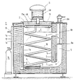
- the device according to the invention is shown schematically simplified in section in an exemplary embodiment selected. Parts that are not related to the invention are omitted, such as the mechanism for opening and sealing the container lid, the collecting container mentioned above and the associated overflow in the treatment container, as well as the heating and cooling connections.
- the device comprises a double-walled container 1, which is sealed by a lid 2. There is thermal insulation 1c between the outer container wall 1a and the inner container wall 1b. Suitable electrical heating elements 3 are attached near the inner container wall 1b, to which the container bottom is also counted, the electrical connecting lines of which are not shown. On the cover 2 there is a tubular attachment 4, the filter, for. B. contains an activated carbon filter 4a, which is connected via a pipe socket 4b with the interior of the treatment container 1.
- This interior is filled with a liquid heat transfer medium, not shown here, which can be heated by the electrical heating device 3 to a preselected temperature, which can be up to around 400 ° C.
- a liquid heat transfer medium not shown here
- the treatment container 1 can have a basket-like insert for this purpose (not shown).
- a ring line 11 Arranged in the container 1 above the liquid level F of the heat transfer medium is a ring line 11, which has a number of holes 11a, which are preferably directed obliquely onto the central axis of the container 1.
- the ring line 11 is via a line 12 which is connected to a valve 13 is equipped with a nitrogen bottle 14 connected.
- valve 13 is opened briefly, preferably automatically via a sequence control (not shown).
- the nitrogen then flowing out through the holes 11a displaces the air above the liquid level F.
- the air escapes via the pipe socket 4b and the activated carbon filter 4a in the attachment 4 arranged on the cover 2.
- the heat transfer medium is heated by means of the heating device 3 to the preset temperature, which is not too far above the melting temperature of the plastic adhering to the parts to be cleaned, so that its decomposition is avoided as much as possible, especially since gaseous products can also be formed here.
- the cleaned plastic usually floats and then collects on the surface of the heat transfer medium.
- the tubular pump chamber 5 shown is incorporated at one point of the container between the outer container wall 1a and the inner container wall 1b, which via an upper channel 6 and a lower channel 7 connects to the interior of the container 1 is connected, that is also filled with the heat transfer medium, the upper fill level is expediently dimensioned such that it is above the upper channel 6, z. B. lies with the brand F.
- the impeller 8a of a pump is immersed, the drive motor, for. B is an electric motor 8b, which is located outside the container 1 and is connected to the impeller 8a via a shaft 8c of corresponding length.
- a corresponding electrical control ensures that the heating device 3 can only be switched on together with the pump motor 8b.
- the liquid flow generated by the impeller 8a and preferably running in the direction of the arrows not only ensures uniform and therefore rapid heating of the heat transfer medium without the risk of local overheating, but also rinses the parts to be cleaned which have been inserted into the interior of the container, as has been shown that even at a relatively low flow rate, the cleaning effect is better than in a comparable device according to the prior art, in which the heat transfer medium is set in vibration by means of an electromagnetic or pneumatic device.
- a helical cooling tube 10 is arranged in the interior of the treatment container 1, which is fed with a cooling medium, most simply with water.
- the cooling time is naturally also shortened if the pump motor 8b remains switched on during this time.
- cover 2 is often also heat-insulating.
- baffles, guide rails or the like are provided in the interior of the treatment container 1, which prevent the parts to be cleaned or the basket containing them from coming into direct contact with the inner container wall 1b or with the cooling tube 10, so that damage to the parts in question is avoided .
Abstract
Description
Die Erfindung betrifft eine Vorrichtung der im Oberbegriff des Patentanspruches 1 angegebenen Art.The invention relates to a device of the type specified in the preamble of
Eine derartige Vorrichtung ist aus der DE-PS 37 12 640 bekannt. Das mit ihr verwirklichte Reinigungsprinzip hat den Vorteil, daß im Regelfall und bei bestimmungsgemäßem Gebrauch der Kunststoff nicht zersetzt wird, so daß keine toxischen oder sonst die Umwelt schädigenden Gase entstehen, die eine stationäre Aufstellung der Vorrichtung und ihre Verbindung mit einem entsprechenden Abzugsystem notwendig machen würden. Als das Wärmeträgermedium in Bewegung versetzende und dadurch die Reinigungswirkung unterstützende Vorrichtung dient ein Druckluftvibrator, der in den auf dem Deckel des Behälters angeordneten Abluftfilter integriert ist und über einen in das Wärmeträgermedium eintauchenden Teller dieses in Schwingungen versetzt. Der Behälter ist des weiteren mit einem Auffangbehälter über einen Überlauf verbunden.Such a device is known from DE-PS 37 12 640. The cleaning principle implemented with it has the advantage that, as a rule and when used as intended, the plastic is not decomposed, so that no toxic or otherwise harmful gases are generated which would make it necessary to install the device in a stationary manner and to connect it to an appropriate exhaust system . A compressed air vibrator is used as the device which sets the heat transfer medium in motion and thereby supports the cleaning action, which is integrated in the exhaust air filter arranged on the cover of the container and which sets this in vibration through a plate immersed in the heat transfer medium. The container is also connected to a collecting container via an overflow.
Insbesondere wenn die bekannte Vorrichtung mit einem Behandlungsbehälter großen Volumens ausgestattet ist, nimmt das Aufheizen des Wärmeträgermediums wie auch ggf. dessen Abkühlung eine beträchtliche Zeit in Anspruch. Eine Verkürzung der Aufheizzeit durch Erhöhung der Heizleistung ist nur in sehr begrenztem Umfang möglich, da es leicht zu örtlichen Überhitzungen und damit einhergehenden Zersetzungserscheinungen des Wärmeträgermediums kommen kann. Ein weiterer Nachteil der bekannten Vorrichtung besteht darin, daß das nicht unerhebliche Luftvolumen oberhalb des Flüssigkeitsspiegels bei den bis zu 400°C betragenden Temperaturen einen Teil des Wärmeträgermediums und fallweise auch der abgereinigten Kunststoffreste durch Oxydation zersetzt, uzw. umso mehr, je länger die Aufheizung, die eigentliche Reinigung und die Abkühlung dauern.In particular, if the known device is equipped with a treatment tank of large volume, the heating up of the heat transfer medium and possibly also its cooling take up a considerable time. Shortening the heating time by increasing the heating output is only possible to a very limited extent, since it is easy local overheating and associated decomposition of the heat transfer medium can occur. Another disadvantage of the known device is that the not inconsiderable volume of air above the liquid level at temperatures up to 400 ° C decomposes part of the heat transfer medium and, in some cases, the cleaned plastic residues by oxidation, etc. the longer, the longer the heating, the actual cleaning and the cooling take.
Der Erfindung liegt daher die Aufgabe zugrunde, eine Vorrichtung der einleitend angegebenen Gattung zu schaffen, die eine verkürzte Aufheizzeit, eine kürzere Reinigungsdauer und zutreffendenfalls auch eine verkürzte Kühlzeit hat.The invention is therefore based on the object of creating a device of the type specified in the introduction, which has a shortened heating-up time, a shorter cleaning time and, if applicable, also a shortened cooling time.
Diese Aufgabe ist durch die im kennzeichnenden Teil des Patentanspruches 1 angegebenen Merkmale gelöst.This object is achieved by the features specified in the characterizing part of
Aus dem DE-GM 78 20 264 ist ein Behälter zur Reinigung von Metallteilen mittels einer Reinigungsflüssigkeit bekannt. Der Behälter enthält eine Flügelradpumpe in einer rohrförmigen Pumpenkammer, deren Achse parallel zur Mittelachse der Behandlungskammer verläuft und die mit der Behandlungskammer über einen oberen Kanal und einen unteren Kanal verbunden ist. Durch die Flügelradpumpe und zusätzliche Leitbleche wird die Reinigungsflüssigkeit auf eine sehr hohe Strömungsgeschwindigkeit von bis zu 40 m/s gebracht, um die Reinigung durch mechanisches Bespülen der Metallteile zu verbessern. Hingegen stellen sich bei dem bekannten Reinigungsbehälter das oben genannte Zersetzungsproblem und die daraus resultierende Aufgabe der vorliegenden Erfindung nicht. Umgekehrt trägt die hier vorgeschlagene Umwälzung des Wärmeträgermediums - für sich betrachtet - weder zu einer Verkürzung der Reinigungszeit noch zu einer Verbesserung des Reinigungsergebnisses bei. Grund hierfür ist, daß die Reinigung weder auf mechanischem noch auf physikalisch/chemischen Wege, d.h. dadurch, daß die Kunststoffreste in dem Wärmeträgermedium in Lösung gehen, erreicht wird. Vielmehr beruht die Reinigungswirkung auf dem rein physikalischen Prozess der Verflüssigung der Kunststoffreste. Hierbei wird durch die Umwälzung des Wärmeträgermediums dessen örtliche Überhitzung vermieden. Dies ermöglicht die Installation einer höheren Heizleistung und die Regelung auf eine höhere Reinigungstemperatur. Dies führt zu einer Verkürzung sowohl der Aufheizzeit als auch der Reinigungszeit und schließlich der Kühlzeit. Neben einer beträchtlichen Verkürzung der Dauer eines Reinigungszyklus wird im Zusammenwirken mit der ebenfalls vorgeschlagenen Verdrängung des Luftsauerstoffes durch eine Inertgasspülung die Zersetzung des Wärmeträgermediums und gegebenenfalls der abgereinigten Kunststoffreste erheblich verringert, also die Nutzungsdauer des Wärmeträgermediums wesentlich verlängert und die Entstehung von umweltschädlichen Zersetzungsprodukten hintangehalten.From DE-GM 78 20 264 a container for cleaning metal parts using a cleaning liquid is known. The container contains an impeller pump in a tubular pump chamber, the axis of which runs parallel to the central axis of the treatment chamber and which is connected to the treatment chamber via an upper channel and a lower channel. The impeller pump and additional guide plates bring the cleaning liquid to a very high flow rate of up to 40 m / s in order to improve cleaning by mechanically flushing the metal parts. On the other hand, the above-mentioned decomposition problem and the resultant object of the present invention do not arise in the known cleaning container. Conversely, the circulation of the heat transfer medium proposed here - viewed in itself - neither contributes to a shortening of the cleaning time nor to an improvement in the cleaning result. The reason for this is that the cleaning is achieved neither mechanically nor physically / chemically, ie by the plastic residues dissolving in the heat transfer medium. Rather, the cleaning effect is based on the purely physical process of liquefying the plastic residues. The local overheating is avoided by the circulation of the heat transfer medium. This enables the installation of a higher heating output and the regulation to a higher cleaning temperature. This leads to a reduction in both the heating-up time and the cleaning time and finally the cooling time. In addition to a considerable reduction in the duration of a cleaning cycle, the decomposition of the heat transfer medium and, if applicable, the cleaned plastic residues are considerably reduced in cooperation with the likewise proposed displacement of the atmospheric oxygen by an inert gas purging, i.e. the service life of the heat transfer medium is significantly extended and the formation of environmentally harmful decomposition products is prevented.
Eine bevorzugte weil konstruktiv einfache und wirksame Ausführungsform der Vorrichtung nach der Erfindung ist im Anspruch 2 angegeben.A preferred because of structurally simple and effective embodiment of the device according to the invention is specified in
Da an die Pumpe keine besonderen Anforderungen gestellt werden, genügt die in Anspruch 3 genannte Ausführung als Flügelradpumpe.Since no special requirements are placed on the pump, the design as an impeller pump mentioned in
Gemäß Anspruch 4 kann der Pumpenmotor außerhalb des Behandlungsbehälters angeordnet sein, braucht also weder gekapselt noch besonders hitzeunempfindlich zu sein.According to claim 4, the pump motor can be arranged outside the treatment container, so it does not need to be encapsulated or particularly insensitive to heat.
Die Ausführungsform nach Anspruch 5 vermeidet unnötige Wärmeverluste.The embodiment according to
In der Zeichnung ist die Vorrichtung nach der Erfindung in einer beispielhaft gewählten Ausführungsform schematisch vereinfacht im Schnitt dargestellt. Teile, die in keinem Zusammenhang mit der Erfindung stehen, sind weggelassen, so etwa die Mechanik zum Öffnen und dichten Verschließen des Behälterdeckels, der eingangs bereits erwähnte Auffangbehälter und der zugehörige Überlauf in dem Behandlungsbehälter, sowie die Heiz- und Kühlanschlüsse.In the drawing, the device according to the invention is shown schematically simplified in section in an exemplary embodiment selected. Parts that are not related to the invention are omitted, such as the mechanism for opening and sealing the container lid, the collecting container mentioned above and the associated overflow in the treatment container, as well as the heating and cooling connections.
Die Vorrichtung umfaßt einen doppelwandigen Behälter 1, der durch einen Deckel 2 dicht verschlossen ist. Zwischen der äußeren Behälterwand 1a und der inneren Behälterwand 1b befindet sich eine Wärmeisolierung 1c. Nahe der inneren Behälterwand 1b, zu der auch der Behälterboden gezählt wird, sind geeignete elektrische Heizstäbe 3 angebracht, deren elektrische Verbindungsleitungen nicht dargestellt sind. Auf dem Deckel 2 befindet sich ein rohrförmiger Aufsatz 4, der einen Filter, z. B. einen Aktivkohlefilter 4a enthält, der über einen Rohrstutzen 4b mit dem Innenraum des Behandlungsbehälters 1 in Verbindung steht.The device comprises a double-
Dieser Innenraum ist mit einem hier nicht dargestellten, flüssigen Wärmeträgermedium gefüllt, das sich durch die elektrische Heizvorrichtung 3 bis auf eine vorgewählte Temperatur erhitzen läßt, die bis zu rund 400° C betragen kann. In dieses Wärmeträgermedium werden nach Abheben des Deckels 2 diejenigen Teile von Kunststoffverarbeitungsmaschinen, beispielsweise Extruderschnecken, Spritzköpfe, Angußverteiler und dergleichen eingelegt, an denen Kunststoffreste anhaften. Der Behandlungsbehälter 1 kann hierzu einen korbartigen Einsatz haben (nicht dargestellt).This interior is filled with a liquid heat transfer medium, not shown here, which can be heated by the
Oberhalb des Flüssigkeitsspiegels F des Wärmeträgermediums ist in dem Behälter 1 eine Ringleitung 11 angeordnet, die eine Anzahl von vorzugsweise schräg auf die Mittelachse des Behälters 1 gerichteten Löchern 11a hat. Die Ringleitung 11 ist über eine Leitung 12, die mit einem Ventil 13 ausgestattet ist, mit einer Stickstofflasche 14 verbunden.Arranged in the
Nach dem Verschließen des Deckels 2 wird das Ventil 13 - vorzugsweise selbsttätig über eine nicht dargestellte Ablaufsteuerung - kurzzeitig geöffnet. Der dann über die Löcher 11a ausströmende Stickstoff verdrängt die Luft oberhalb des Flüssigkeitsspiegels F. Die Luft entweicht über den Rohrstutzen 4b und den Aktivkohlefilter 4a in dem auf dem Deckel 2 angeordneten Aufsatz 4.After the
Gleichzeitig oder anschließend wird das Wärmeträgermedium mittels der Heizvorrichtung 3 auf die voreingestellte Temperatur erhitzt, die nicht allzu weit über der Schmelztempteratur des an den zu reinigenden Teilen haftenden Kunststoffs liegt, damit dessen Zersetzung möglichst vermieden wird, zumal hierbei auch gasförmige Produkte entstehen können. Der abgereinigte Kunststoff schwimmt gewöhnlich auf und sammelt sich dann auf der Oberfläche des Wärmeträgermediums.Simultaneously or subsequently, the heat transfer medium is heated by means of the
Zur Beschleunigung des Aufheizvorganges wie auch des eigentlichen Reinigungsvorganges ist an einer Stelle des Behälters zwischen die äußere Behälterwand 1a und die innere Behälterwand 1b die dargestellte, rohrförmige Pumpenkammer 5 eingearbeitet, die über einen oberen Kanal 6 und einen unteren Kanal 7 mit dem Innenraum des Behälters 1 in Verbindung steht, also ebenfalls mit dem Wärmeträgermedium gefüllt ist, dessen oberer Füllstand zweckmäßig so bemessen ist, daß er oberhalb des oberen Kanales 6, z. B. bei der Marke F liegt. In die Pumpenkammer 5 taucht das Flügelrad 8a einer Pumpe ein, deren Antriebsmotor, z. B ein Elektromotor 8b, sich außerhalb des Behälters 1 befindet und mit dem Flügelrad 8a über eine Welle 8c entsprechender Länge verbunden ist.To accelerate the heating process as well as the actual cleaning process, the
Über eine entsprechende elektrische Steuerung ist sichergestellt, daß die Heizeinrichtung 3 stets nur zusammen mit dem Pumpenmotor 8b eingeschaltet werden kann. Der durch das Flügelrad 8a erzeugte und vorzugsweise in Richtung der eingezeichneten Pfeile laufende Flüssigkeitsstrom sorgt nicht nur für eine gleichmäßige und daher rasche Erwärmung des Wärmeträgermediums ohne die Gefahr lokaler Überhitzungen, sondern umspült auch die in das Behälterinnere eingelegten, zu reinigenden Teile, wobei sich gezeigt hat, daß auch bei verhältnismäßig geringer Strömungsgeschwindigkeit die Reinigungswirkung besser ist als bei einer vergleichbaren Vorrichtung nach dem Stand der Technik, bei der das Wärmeträgermedium mittels einer elektromagnetischen oder pneumatischen Vorrichtung in Schwingungen versetzt wird.A corresponding electrical control ensures that the
Um nach erfolgter Reinigung die Abkühlung zu beschleunigen, ist im Inneren des Behandlungsbehälters 1 ein schraubenförmig verlaufendes Kühlrohr 10 angeordnet, das mit einem Kühlmedium, am einfachsten mit Wasser, gespeist wird. Auch die Abkühlzeit verkürzt sich naturgemäß, wenn währenddessen der Pumpenmotor 8b eingeschaltet bleibt.In order to accelerate the cooling after cleaning, a
Wir bereits erwähnt, sind in der Zeichnung nur die für das Verständnis der Erfindung wesentlichen Teile dargestellt. Unter anderem ist in der Praxis häufig der Deckel 2 ebenfalls wärmeisolierend ausgebildet. Weiter sind im Inneren des Behandlungsbehälters 1 Abweisbleche, Führungsschienen oder dergleichen vorgesehen, die verhindern, daß die zu reinigenden Teile oder der diese enthaltende Korb in direkte Berührung mit der inneren Behälterwand 1b oder mit dem Kühlrohr 10 kommen, so daß Beschädigungen der betreffenden Teile vermieden werden.We already mentioned, only the parts essential for understanding the invention are shown in the drawing. Among other things, in practice the
Claims (5)
- An apparatus for cleaning those parts of synthetic plastics processing machinery on which synthetic plastics residues cling, the apparatus consisting of a processing tank (1) which receives the parts in a processing chamber and having a cover (2) which carries an activated charcoal waste air filter (4) which is connected to the interior of the tank (1) and with a heating means (3) which heats a liquid heat carrier medium in the processing chamber to a temperature which is above the melting temperature of the synthetic plastics material clinging to the parts which are to be cleaned, and with a device which imparts motion to the heat carrier medium, characterised in that the apparatus consists of a pump (8a, 8b, 8c) the intake side (at 6) of which is connected to the processing chamber close to the top filling level (F) of the heat carrier medium and of which the output side (at 7) is connected to the processing chamber close to its bottom and in that there is in the tank (1) above the upper filling level (F) of heat carrier medium a ring pipe (11) provided with a plurality of holes (11a) directed at the central axis of the container (1) and which is connected by a valve (13) to an inert gas source (14).
- An apparatus according to claim 1, characterised in that the pump is disposed in a tubular pump chamber (5) the axis of which extends parallel with the central axis through the processing chamber and which is connected to the processing chamber via an upper passage (6) and a lower passage (7).
- An apparatus according to claim 1 or 2, characterised in that the pump member of the pump is an impeller (8a).
- An apparatus according to claim 3, characterised in that the pump motor (8b) is disposed outside the tank (1).
- An apparatus according to one of claims 2 to 4, characterised in that the heat insulation (1c) of the container (1) also encloses the tubular pump chamber (5).
Priority Applications (1)
| Application Number | Priority Date | Filing Date | Title |
|---|---|---|---|
| AT89108176T ATE84743T1 (en) | 1988-05-27 | 1989-05-05 | DEVICE FOR CLEANING PARTS OF PLASTIC PROCESSING MACHINERY WHICH HAVE PLASTIC REMAINS ADHERED. |
Applications Claiming Priority (2)
| Application Number | Priority Date | Filing Date | Title |
|---|---|---|---|
| DE3818144 | 1988-05-27 | ||
| DE3818144 | 1988-05-27 |
Publications (3)
| Publication Number | Publication Date |
|---|---|
| EP0343413A2 EP0343413A2 (en) | 1989-11-29 |
| EP0343413A3 EP0343413A3 (en) | 1991-01-16 |
| EP0343413B1 true EP0343413B1 (en) | 1993-01-20 |
Family
ID=6355303
Family Applications (1)
| Application Number | Title | Priority Date | Filing Date |
|---|---|---|---|
| EP89108176A Expired - Lifetime EP0343413B1 (en) | 1988-05-27 | 1989-05-05 | Apparatus for cleaning elements of plastics processing machines on which plastic has stuck |
Country Status (6)
| Country | Link |
|---|---|
| US (1) | US4919161A (en) |
| EP (1) | EP0343413B1 (en) |
| AT (1) | ATE84743T1 (en) |
| CA (1) | CA1324946C (en) |
| DE (2) | DE8816444U1 (en) |
| ES (1) | ES2037321T3 (en) |
Families Citing this family (10)
| Publication number | Priority date | Publication date | Assignee | Title |
|---|---|---|---|---|
| NL9200323A (en) * | 1992-02-21 | 1993-09-16 | Handelsonderneming H Swanenber | METHOD AND APPARATUS FOR REMOVING BITUMES FROM TUBES OR PIPES |
| KR950009305B1 (en) * | 1992-03-14 | 1995-08-19 | 주식회사에스·케이·씨 | Apparatus and method for washing drum filter |
| DE4302415C1 (en) * | 1993-01-28 | 1993-12-09 | Christ Caroline | Cleaning adhering residues from plastics processing equipment - by placing component concerned in medium heated to softening point of polymer and directing pressurised jets of same medium on to it |
| DE4438542B4 (en) * | 1994-10-28 | 2004-11-18 | Conpro - Coding Gmbh | Device for cleaning machine parts |
| DE102004007929B4 (en) * | 2004-02-18 | 2006-03-30 | Kiefel Extrusion Gmbh | Method and device for cleaning a blown head for plastic films |
| US8080506B2 (en) * | 2009-07-14 | 2011-12-20 | MSI Technology LLC. | Reactive purge compound for polymer purging |
| CN102873050B (en) * | 2012-09-25 | 2014-12-10 | 汕头可逸塑胶有限公司 | Cleaning device and method |
| US11578144B2 (en) | 2018-05-23 | 2023-02-14 | 2569924 Ontario Inc. | Compositions and methods for removing contaminants from plastics processing equipment |
| CN113513651B (en) * | 2021-07-13 | 2022-08-05 | 重庆交通大学 | Device for preventing calcium bicarbonate solution from crystallizing on inner wall of pipeline in tunnel |
| CN116162321B (en) * | 2023-04-25 | 2023-06-23 | 汕头市华麟塑化有限公司 | Glass fiber reinforced flame-retardant high-impact polystyrene modified material and preparation method thereof |
Family Cites Families (9)
| Publication number | Priority date | Publication date | Assignee | Title |
|---|---|---|---|---|
| DD77387A (en) * | ||||
| US2151354A (en) * | 1935-10-07 | 1939-03-21 | Robot Hand Corp | Washing and drying apparatus |
| US3319638A (en) * | 1965-09-23 | 1967-05-16 | Claude R Ellison | Engine block washing tank |
| SE324938B (en) * | 1969-02-04 | 1970-06-15 | Uddeholms Ab | |
| DE7820264U1 (en) * | 1978-07-06 | 1979-04-05 | Kurt Hofmann Kg Maschinen-Apparate- Und Stahlbau, 8542 Roth | Metal parts washing machine |
| US4375819A (en) * | 1981-04-17 | 1983-03-08 | Hurri-Kleen Corporation | Apparatus for cleaning machinery parts and the like |
| DE3145815C2 (en) * | 1981-11-19 | 1984-08-09 | AGA Gas GmbH, 2102 Hamburg | Process for removing peelable layers of material from coated objects, |
| DE3309878C1 (en) * | 1983-03-18 | 1984-06-14 | Caroline Christ Fabrikation chemischer Erzeugnisse, 8060 Dachau | Device for cleaning those parts of plastic processing machines to which plastic residues adhere |
| DE3712640C1 (en) * | 1987-04-14 | 1988-05-19 | Christ Abgasfreie Werkzeugrein | Device for cleaning those parts of plastic processing machines to which plastic residues adhere |
-
1988
- 1988-05-27 DE DE8816444U patent/DE8816444U1/de not_active Expired
-
1989
- 1989-05-05 ES ES198989108176T patent/ES2037321T3/en not_active Expired - Lifetime
- 1989-05-05 AT AT89108176T patent/ATE84743T1/en not_active IP Right Cessation
- 1989-05-05 DE DE8989108176T patent/DE58903319D1/en not_active Expired - Fee Related
- 1989-05-05 EP EP89108176A patent/EP0343413B1/en not_active Expired - Lifetime
- 1989-05-19 US US07/354,454 patent/US4919161A/en not_active Expired - Fee Related
- 1989-05-26 CA CA000601524A patent/CA1324946C/en not_active Expired - Fee Related
Also Published As
| Publication number | Publication date |
|---|---|
| ATE84743T1 (en) | 1993-02-15 |
| DE8816444U1 (en) | 1989-08-24 |
| DE58903319D1 (en) | 1993-03-04 |
| CA1324946C (en) | 1993-12-07 |
| EP0343413A3 (en) | 1991-01-16 |
| EP0343413A2 (en) | 1989-11-29 |
| US4919161A (en) | 1990-04-24 |
| ES2037321T3 (en) | 1993-06-16 |
Similar Documents
| Publication | Publication Date | Title |
|---|---|---|
| EP0343413B1 (en) | Apparatus for cleaning elements of plastics processing machines on which plastic has stuck | |
| DE1571011B2 (en) | Process for coating long objects by vortex sintering | |
| DE2610415B2 (en) | Discharge device for heat fusible material | |
| DE2034404C3 (en) | Casting furnace for the production of structure-oriented castings | |
| DE102009026935B4 (en) | Hardening machine for inductive hardening under inert gas | |
| DE2807402C2 (en) | Device for removing residues on devices by pyrolysis | |
| DE2715237C3 (en) | Device for vacuum impregnation of plates of a porous material | |
| DE3637070C2 (en) | ||
| DE1433816B2 (en) | Atmospheric sealing | |
| DE3712640C1 (en) | Device for cleaning those parts of plastic processing machines to which plastic residues adhere | |
| DE3309878C1 (en) | Device for cleaning those parts of plastic processing machines to which plastic residues adhere | |
| DE3146478C2 (en) | Device for cleaning spray nozzles, screw conveyors and the like. Parts of plastic injection molding machines from adhering residues of thermoplastics | |
| DE2815739C3 (en) | Closure device for the filling opening of a cooling chamber of a system for dry coke cooling | |
| DE3046171C2 (en) | Method and device for impregnating porous materials, in particular carbon products, in the manufacture of carbon electrodes | |
| DE3915140A1 (en) | Apparatus for cleaning those parts of plastics processing machines on which remains of plastic adhere | |
| DE60221410T2 (en) | DEVICE FOR FOLL-CLOSING PACKAGING IN A MACHINE FOR CONDITIONING UNDER CONTROLLED ATMOSPHERE | |
| DE3244090A1 (en) | DEVICE FOR CONVEYING LIQUIDS AND FOR SEPARATING GASES CONTAINED IN THE LIQUIDS | |
| DE19846591A1 (en) | Device and method for flushing around rod elements | |
| EP0221329B1 (en) | Process and device for quenching annealed stock | |
| DE4014408C1 (en) | Heating materials during work process in closed work area - involves rotating work member, feeding gaseous heat carrier into handling zone and then removing gas | |
| DE3237193A1 (en) | METHOD AND DEVICE FOR HEAT TREATMENT OF TUBES | |
| DE102016124641A1 (en) | soldering device | |
| DE4438542B4 (en) | Device for cleaning machine parts | |
| DE4417018C1 (en) | Telegraph poles, fence poles, vine rods | |
| DE2113287C3 (en) | Lowering and transport device for a multi-station vacuum furnace for the heat treatment of metallic workpieces |
Legal Events
| Date | Code | Title | Description |
|---|---|---|---|
| PUAI | Public reference made under article 153(3) epc to a published international application that has entered the european phase |
Free format text: ORIGINAL CODE: 0009012 |
|
| AK | Designated contracting states |
Kind code of ref document: A2 Designated state(s): AT BE CH DE ES FR GB GR IT LI LU NL SE |
|
| PUAL | Search report despatched |
Free format text: ORIGINAL CODE: 0009013 |
|
| AK | Designated contracting states |
Kind code of ref document: A3 Designated state(s): AT BE CH DE ES FR GB GR IT LI LU NL SE |
|
| 17P | Request for examination filed |
Effective date: 19910402 |
|
| 17Q | First examination report despatched |
Effective date: 19920701 |
|
| GRAA | (expected) grant |
Free format text: ORIGINAL CODE: 0009210 |
|
| AK | Designated contracting states |
Kind code of ref document: B1 Designated state(s): AT BE CH DE ES FR GB GR IT LI LU NL SE |
|
| REF | Corresponds to: |
Ref document number: 84743 Country of ref document: AT Date of ref document: 19930215 Kind code of ref document: T |
|
| ITF | It: translation for a ep patent filed |
Owner name: BARZANO' E ZANARDO MILANO S.P.A. |
|
| REF | Corresponds to: |
Ref document number: 58903319 Country of ref document: DE Date of ref document: 19930304 |
|
| GBT | Gb: translation of ep patent filed (gb section 77(6)(a)/1977) |
Effective date: 19930211 |
|
| ET | Fr: translation filed | ||
| REG | Reference to a national code |
Ref country code: ES Ref legal event code: FG2A Ref document number: 2037321 Country of ref document: ES Kind code of ref document: T3 |
|
| REG | Reference to a national code |
Ref country code: GR Ref legal event code: FG4A Free format text: 3007675 |
|
| PLBE | No opposition filed within time limit |
Free format text: ORIGINAL CODE: 0009261 |
|
| STAA | Information on the status of an ep patent application or granted ep patent |
Free format text: STATUS: NO OPPOSITION FILED WITHIN TIME LIMIT |
|
| 26N | No opposition filed | ||
| EPTA | Lu: last paid annual fee | ||
| EAL | Se: european patent in force in sweden |
Ref document number: 89108176.2 |
|
| PGFP | Annual fee paid to national office [announced via postgrant information from national office to epo] |
Ref country code: SE Payment date: 19970530 Year of fee payment: 9 Ref country code: ES Payment date: 19970530 Year of fee payment: 9 |
|
| PGFP | Annual fee paid to national office [announced via postgrant information from national office to epo] |
Ref country code: GR Payment date: 19970602 Year of fee payment: 9 |
|
| PGFP | Annual fee paid to national office [announced via postgrant information from national office to epo] |
Ref country code: GB Payment date: 19970604 Year of fee payment: 9 |
|
| PGFP | Annual fee paid to national office [announced via postgrant information from national office to epo] |
Ref country code: LU Payment date: 19970702 Year of fee payment: 9 |
|
| PG25 | Lapsed in a contracting state [announced via postgrant information from national office to epo] |
Ref country code: LU Free format text: LAPSE BECAUSE OF NON-PAYMENT OF DUE FEES Effective date: 19980505 Ref country code: GB Free format text: LAPSE BECAUSE OF NON-PAYMENT OF DUE FEES Effective date: 19980505 |
|
| PG25 | Lapsed in a contracting state [announced via postgrant information from national office to epo] |
Ref country code: SE Free format text: LAPSE BECAUSE OF NON-PAYMENT OF DUE FEES Effective date: 19980506 Ref country code: ES Free format text: LAPSE BECAUSE OF EXPIRATION OF PROTECTION Effective date: 19980506 |
|
| PG25 | Lapsed in a contracting state [announced via postgrant information from national office to epo] |
Ref country code: GR Free format text: LAPSE BECAUSE OF NON-PAYMENT OF DUE FEES Effective date: 19980531 |
|
| PGFP | Annual fee paid to national office [announced via postgrant information from national office to epo] |
Ref country code: AT Payment date: 19980531 Year of fee payment: 10 |
|
| PGFP | Annual fee paid to national office [announced via postgrant information from national office to epo] |
Ref country code: FR Payment date: 19980617 Year of fee payment: 10 |
|
| PGFP | Annual fee paid to national office [announced via postgrant information from national office to epo] |
Ref country code: BE Payment date: 19980623 Year of fee payment: 10 |
|
| PGFP | Annual fee paid to national office [announced via postgrant information from national office to epo] |
Ref country code: NL Payment date: 19980625 Year of fee payment: 10 |
|
| PGFP | Annual fee paid to national office [announced via postgrant information from national office to epo] |
Ref country code: CH Payment date: 19980701 Year of fee payment: 10 |
|
| PGFP | Annual fee paid to national office [announced via postgrant information from national office to epo] |
Ref country code: DE Payment date: 19980716 Year of fee payment: 10 |
|
| GBPC | Gb: european patent ceased through non-payment of renewal fee |
Effective date: 19980505 |
|
| EUG | Se: european patent has lapsed |
Ref document number: 89108176.2 |
|
| PG25 | Lapsed in a contracting state [announced via postgrant information from national office to epo] |
Ref country code: AT Free format text: LAPSE BECAUSE OF NON-PAYMENT OF DUE FEES Effective date: 19990505 |
|
| PG25 | Lapsed in a contracting state [announced via postgrant information from national office to epo] |
Ref country code: LI Free format text: LAPSE BECAUSE OF NON-PAYMENT OF DUE FEES Effective date: 19990531 Ref country code: CH Free format text: LAPSE BECAUSE OF NON-PAYMENT OF DUE FEES Effective date: 19990531 Ref country code: BE Free format text: LAPSE BECAUSE OF NON-PAYMENT OF DUE FEES Effective date: 19990531 |
|
| BERE | Be: lapsed |
Owner name: CAROLINE CHRIST ABGASFREIE WERKZEUGREINIGUNGSAPPA Effective date: 19990531 |
|
| PG25 | Lapsed in a contracting state [announced via postgrant information from national office to epo] |
Ref country code: NL Free format text: LAPSE BECAUSE OF NON-PAYMENT OF DUE FEES Effective date: 19991201 |
|
| REG | Reference to a national code |
Ref country code: CH Ref legal event code: PL |
|
| PG25 | Lapsed in a contracting state [announced via postgrant information from national office to epo] |
Ref country code: FR Free format text: LAPSE BECAUSE OF NON-PAYMENT OF DUE FEES Effective date: 20000131 |
|
| NLV4 | Nl: lapsed or anulled due to non-payment of the annual fee |
Effective date: 19991201 |
|
| PG25 | Lapsed in a contracting state [announced via postgrant information from national office to epo] |
Ref country code: DE Free format text: LAPSE BECAUSE OF NON-PAYMENT OF DUE FEES Effective date: 20000301 |
|
| REG | Reference to a national code |
Ref country code: FR Ref legal event code: ST |
|
| REG | Reference to a national code |
Ref country code: ES Ref legal event code: FD2A Effective date: 20000201 |
|
| PG25 | Lapsed in a contracting state [announced via postgrant information from national office to epo] |
Ref country code: IT Free format text: LAPSE BECAUSE OF NON-PAYMENT OF DUE FEES;WARNING: LAPSES OF ITALIAN PATENTS WITH EFFECTIVE DATE BEFORE 2007 MAY HAVE OCCURRED AT ANY TIME BEFORE 2007. THE CORRECT EFFECTIVE DATE MAY BE DIFFERENT FROM THE ONE RECORDED. Effective date: 20050505 |