EP0343411A2 - Nuclear fuel pellet surface defect inspection apparatus - Google Patents
Nuclear fuel pellet surface defect inspection apparatus Download PDFInfo
- Publication number
- EP0343411A2 EP0343411A2 EP89108148A EP89108148A EP0343411A2 EP 0343411 A2 EP0343411 A2 EP 0343411A2 EP 89108148 A EP89108148 A EP 89108148A EP 89108148 A EP89108148 A EP 89108148A EP 0343411 A2 EP0343411 A2 EP 0343411A2
- Authority
- EP
- European Patent Office
- Prior art keywords
- plates
- pellet
- wall sections
- support substrate
- inspection chamber
- Prior art date
- Legal status (The legal status is an assumption and is not a legal conclusion. Google has not performed a legal analysis and makes no representation as to the accuracy of the status listed.)
- Granted
Links
Images


Classifications
-
- G—PHYSICS
- G21—NUCLEAR PHYSICS; NUCLEAR ENGINEERING
- G21C—NUCLEAR REACTORS
- G21C17/00—Monitoring; Testing ; Maintaining
- G21C17/06—Devices or arrangements for monitoring or testing fuel or fuel elements outside the reactor core, e.g. for burn-up, for contamination
-
- G—PHYSICS
- G01—MEASURING; TESTING
- G01N—INVESTIGATING OR ANALYSING MATERIALS BY DETERMINING THEIR CHEMICAL OR PHYSICAL PROPERTIES
- G01N29/00—Investigating or analysing materials by the use of ultrasonic, sonic or infrasonic waves; Visualisation of the interior of objects by transmitting ultrasonic or sonic waves through the object
- G01N29/22—Details, e.g. general constructional or apparatus details
- G01N29/26—Arrangements for orientation or scanning by relative movement of the head and the sensor
- G01N29/27—Arrangements for orientation or scanning by relative movement of the head and the sensor by moving the material relative to a stationary sensor
-
- G—PHYSICS
- G01—MEASURING; TESTING
- G01N—INVESTIGATING OR ANALYSING MATERIALS BY DETERMINING THEIR CHEMICAL OR PHYSICAL PROPERTIES
- G01N2291/00—Indexing codes associated with group G01N29/00
- G01N2291/04—Wave modes and trajectories
- G01N2291/044—Internal reflections (echoes), e.g. on walls or defects
-
- Y—GENERAL TAGGING OF NEW TECHNOLOGICAL DEVELOPMENTS; GENERAL TAGGING OF CROSS-SECTIONAL TECHNOLOGIES SPANNING OVER SEVERAL SECTIONS OF THE IPC; TECHNICAL SUBJECTS COVERED BY FORMER USPC CROSS-REFERENCE ART COLLECTIONS [XRACs] AND DIGESTS
- Y02—TECHNOLOGIES OR APPLICATIONS FOR MITIGATION OR ADAPTATION AGAINST CLIMATE CHANGE
- Y02E—REDUCTION OF GREENHOUSE GAS [GHG] EMISSIONS, RELATED TO ENERGY GENERATION, TRANSMISSION OR DISTRIBUTION
- Y02E30/00—Energy generation of nuclear origin
- Y02E30/30—Nuclear fission reactors
Definitions
- the present invention relates generally to nuclear fuel pellet inspection and, more particularly, is concerned with an improved apparatus for inspecting fuel pellets for surface defects.
- Nuclear reactors include fuel assemblies which contain pellets of fissionable material as their basic fuel element.
- a pellet ideally takes the form of a right cylinder with slightly concave or dished opposite ends.
- a number of pellets are stacked end to end in a fuel rod cladding tube which, like the pellets, is usually of circular cross-section. Then, a given number of fuel rods are grouped together in a fuel assembly.
- pellets used in the fuel assembly be free of circumferential defects, such as cracks and chips, in order to achieve desired stacking of the pellets within the fuel rod tube as well as uniform heat transfer between the stacked pellets and cladding tube and uniform consumption of the pellets during operation of the reactor core. Consequently, an important step in the manufacture of the nuclear fuel pellet is the inspection of its surface to ascertain whether there are any defects present.
- Exemplary prior art systems for inspecting and classifying nuclear fuel pellets are disclosed in U.S. Patents to Jones (3,221,152; 3,272,332; and 3,282,116), Ryden, Jr. (4,037,103), Marmo (4,193,502), and Wilks et al (4,349,112). While the inspection systems of these prior art patents appear to achieve their objectives under the range of operating conditions for which they were designed, none of these systems appear to be adapted to perform inspection of a pellet for circumferential or surface defects.
- inspection by this apparatus is accomplished while the parts are in transit.
- the parts to be inspected are fed down a chute from a vibratory bowl feeder by a singulation device.
- This acoustically-based system is said to outperform and be more versatile than more traditional vision, laser, tactile and proximity-sensing techniques.
- this "off-the-shelf" inspection apparatus is designed for general purpose parts inspection and sorting and thus cannot be used directly, without modification, to inspect nuclear fuel pellets. Consequently, a need exists for modifications to this inspection apparatus which will dedicate it to nuclear fuel pellet inspection.
- the present invention provides a fuel pellet surface defect inspection apparatus designed to satisfy the aforementioned needs.
- certain improvements are incorporated therein relating to the positioning of pellets in an ultrasonic inspection chamber of the apparatus. These improvements adapt or dedicate the apparatus for inspection of fuel pellets for surface defects such as chips and cracks.
- the present invention is set forth in an apparatus for inspecting nuclear fuel pellets for surface defects as characterized in the claims.
- the inspection apparatus 10 includes a wheeled base 12 and a console 14, a built-in microprocessor-based computer system (not shown) and video display terminal (VDT) keyboard 16 and VDT monitor 18 mounted on the base 12.
- VDT video display terminal
- the prior art inspection apparatus 10 includes an inspection chamber 20 having an ultrasonic inspection head 22 (Figs. 14-16), a heated air system (not shown) for maintaining the inspection chamber 20 and head 22 in the desired operating temperature range. Further, the inspection apparatus 10 includes an inclined inspection track or chute 24 upon which parts are fed from a vibratory bowl feeder 26 by a singulation device 28. The parts slide in single file fashion down the chute 24 under the influence of gravity past the inspection head 22. At the lower end of the chute 24 is positioned two bins, one bin 30 for good parts and one bin 32 for bad parts, and a flipper device 34 being operable for directing the parts to the correct one of the bins 30,32 as determined by the results of the inspection.
- the prior art inspection apparatus 10 carries out acoustical inspection of the shapes of the parts one at a time as they pass through the inspection chamber 20.
- the computer system of the inspection apparatus 10 is taught the shape and orientation of a part having the desired or optimum configuration or shape during an initial "learn mode.”
- Sound waves reflected from any subsequent part being inspected are received by an array of transducers 36 making up the ultrasonic inspection head 22.
- One of the transducers 36A transmits sound waves, whereas the rest of the transducers 36B receive the reflected sound waves.
- the receiving transducers 36B of the inspection head 22 Based on these reflected sound waves, the receiving transducers 36B of the inspection head 22 generate an "acoustic signature" of the part.
- the microprocessor-based computer system interprets these signatures.
- Each part thus generates a unique signature and only parts identical to those programmed in the "learn mode" can create the same signature.
- Defect-free parts are thus determined by comparing the acoustic signatures of parts being inspected to the signatures generated earlier as during the "learn mode.” Parts whose signatures do not conform to the "learned" signature are rejected as defective and diverted by the flipper 34 into the bad parts bin 32. Good parts are not diverted and go into the good parts bin 30.
- the prior art inspection apparatus 10 is modified in accordance with the principles of the present invention to adapt it to inspect nuclear fuel pellets 38 by substituting a single pellet feeder, a pellet guide chute assembly 40 and a pellet discharge conveyor.
- the single pellet feeder and pellet discharge conveyor which do not form part of the present invention need not be illustrated and described herein to gain a complete and thorough understanding of the improvements provided by the present invention.
- a modified inspection apparatus using most of the earlier-described prior art components in conjunction with these improved substituted ones can carry out acoustical inspection of nuclear fuel pellets 12 one at a time for circumferential or surface defects, such as chips and cracks.
- the improvements incorporated by the modified inspection apparatus basically relate to the pellet guide chute assembly 40 (see also Figs. 4-9) disposed in an inclined fashion (similar to the prior art inspection chute 24), and to a cover 42 (see also Figs. 10 to 12) overlying the chute assembly 40 at the inspection chamber 20 adjacent the inspection head 22 and a pellet position sensing arrangement 44 (see also Fig. 13) being positioned at the inspection chamber 20 and the inspection head 22 along the chute assembly 40.
- the pellet guide chute assembly 40 in greater detail.
- the guide chute assembly 40 as before is inclined and extends through the inspection chamber 20.
- the guide chute assembly 40 includes a support substrate 46 composed of a pair of elongated wall sections 48,50, and a pair of elongated plates 52,54.
- the wall sections 48,50 of the chute assembly substrate 40 each have a pair of opposite spaced longitudinal edges 48A,48B and 50A, 50B.
- the wall sections 48,50 are rigidly attached together along inner or adjacent ones 48A,50A of their longitudinal edges to form a corner 56 and are angularly displaced from one another at outer or remote ones 48B,50B of the longitudinal edges to provide the substrate 40 with a generally ninety-degree, V-shaped configuration in cross section.
- the plates 52,54 are attached on respective upper adjacent sides of the support substrate wall sections 48,50 for supporting a nuclear fuel pellet 38 between and on adjacent longitudinal portions 52A,54A of as the plates being located within the inspection chamber 20.
- the plates 52,54 have aperture means in the form of slots 58,60 and cutout regions 62,64 underlying the pellet 38 at the respective adjacent longitudinal portions 52A,54A of the plates.
- the slots 58,60 and cutout regions 62,64 which are defined through the plates 52,54 expose respective upper side portions 48C,50C and an interior corner portion 56A of the support substrate wall sections 48,50 also underlying the pellet to the interior of the inspection chamber 20 such that acoustical energy can be propagated to and from bottom and side portions 38A, 38B of the pellet 38 resting adjacent the respective longitudinal portions 52A,54A of the plates via reflection of the acoustical energy from the exposed support substrate wall section side and corner portions 48C,50C and 56A.
- the respective cutout regions 62,64 are defined in inner or adjacent ones 52B,54B of opposite longitudinal edges of the plates 52,54 at adjacent longitudinal portions 52A,54A thereof, whereas the respective slots 58,60 are defined between and spaced from the cutout regions 62,64 and the outer or remote ones 52C,54C of the longitudinal edges of the plates.
- the spaced slots 58,60 and cutout regions 62,64 of the respective plates 52,54 define ligaments 66,68 in the plates 52,54 therebetween at the adjacent longitudinal plate portions 52A,54A upon which the pellet 38 rests, as can be seen in Figs. 8 and 9.
- Figs. 6 to 9 also illustrate means for adjustably attaching the plates 52,54 to the upper adjacent sides of the support substrate wall sections 48,50 for allowing sliding lateral movement thereon toward and away from the adjacent longitudinal edges 48A,50A of the wall sections 48,50.
- Such adjustability of the plates 52,54 allows relocation of the plates to the desired stationary positions thereon for supporting nuclear fuel pellets of different diameters between and on the ligaments 66,68 of the adjacent longitudinal portions 52A,54A of the plates being located in the inspection chamber 20 of the modified inspection apparatus.
- lateral movement of the plates 52,54 correspondingly lengthens or shortens the distance between their ligaments 66,68 to accommodate placement thereon of pellets 38 having different diameters.
- the attaching means of the guide chute assembly 40 for adjustably attaching the plates 52,54 to the wall sections 48,50 of the support substrate 46 include a plurality of elongated holes 70 in the form of elongated slots defined through the plates 52,54 and a plurality of removable fasteners 72 inserted through the holes 70 and threadably anchored to the wall sections 48,50.
- the fasteners 72 can be turned to partially unthread them from the wall sections 48,50 and loosen the plates 52,54 for adjustment. Then, once the plates 52,54 have been slidably moved to the desired positions, the fasteners 72 are retightened to reattach the plates at the desired stationary positions on the support substrate wall sections 48,50.
- the cover 42 has a planar central section 42A and opposite downturned opposite edges 42B,42C applied over the guide chute assembly 40 at the inspection chamber 20.
- the cover 42 provides a means for reflecting and confining the acoustical energy within the inspection chamber.
- the cover 42 contains a plurality of openings in the form of elongated slots 74 defined through the cover 42 so as to extend generally parallel to one another and generally perpendicular to a longitudinal path of sliding movement of the pellet 38 down the inclined chute assembly 40 through the inspection chamber 20.
- the cover 42 also has an opening or notch 76 defined therethrough which receives the ultrasonic inspection head 22 having a housing 22A mounting the acoustical energy transmitting and receiving transducers 36A,36B, as best seen in Figs. 14 to 16, for transmitting acoustical energy into and receive it from the inspection chamber 20 for propagating such energy to and from the pellet 38 therein.
- the pellet position sensing arrangement 44 of the modified inspection apparatus is associated with the support substrate 46 and the cover 42 at the inspection chamber 20 for sensing the position of the pellet 38 as the same slides under the influence of gravity down the inclined guide chute assembly 40 along the longitudinal path through the inspection chamber.
- the support substrate 46 has an elongated opening or slit 78 defined therethrough at its corner 56 and being aligned with the cutout regions 62,64 of the plates 52,54 so as to extend along the longitudinal path of the pellet 38 through the inspection chamber 20.
- the slots 74 in the cover 42 are spaced apart along longitudinal path of the pellet through the inspection chamber 20.
- the pellet position sensing arrangement 44 includes a light transmitting device 80 disposed at the exterior of the substrate corner 56 and aligned with elongated slit 78 therethrough for transmitting light through the open slit and across the inspection chamber 20.
- the arrangement 44 also includes a plurality of light receiving devices 82 disposed at the exterior of the cover 42 and aligned with the respective slots 74 therethrough for receiving light transmitted through the cover slots 74 from across the inspection chamber 20 by the light transmitting device 80.
- the elongated substrate slit 78 is defined through the corner 56 of the substrate 46 formed by the rigidly attached wall sections 48,50 thereof.
- the interior corner portion 56A exposed by the adjacent cutout regions 62,64 of the plates 52,54 not only underlies the adjacent cutout regions but also contains the elongated open slit 78 in the substrate 46.
- the elongated slit also underlies the bottom of the pellet 38 being supported between the adjacent longitudinal portions 52A,54A of the plates 52,54 such that path of the light transmitted by the light transmitting device 80 to the light receiving devices 82 is interrupted by the pellet 38 as the latter slides alons its longitudinal path between the devices 80,82.
Abstract
Description
- The present invention relates generally to nuclear fuel pellet inspection and, more particularly, is concerned with an improved apparatus for inspecting fuel pellets for surface defects.
- Nuclear reactors include fuel assemblies which contain pellets of fissionable material as their basic fuel element. In one exemplary embodiment, a pellet ideally takes the form of a right cylinder with slightly concave or dished opposite ends. For incorporation into fuel assemblies, a number of pellets are stacked end to end in a fuel rod cladding tube which, like the pellets, is usually of circular cross-section. Then, a given number of fuel rods are grouped together in a fuel assembly.
- It is essential that all pellets used in the fuel assembly be free of circumferential defects, such as cracks and chips, in order to achieve desired stacking of the pellets within the fuel rod tube as well as uniform heat transfer between the stacked pellets and cladding tube and uniform consumption of the pellets during operation of the reactor core. Consequently, an important step in the manufacture of the nuclear fuel pellet is the inspection of its surface to ascertain whether there are any defects present.
- Exemplary prior art systems for inspecting and classifying nuclear fuel pellets are disclosed in U.S. Patents to Jones (3,221,152; 3,272,332; and 3,282,116), Ryden, Jr. (4,037,103), Marmo (4,193,502), and Wilks et al (4,349,112). while the inspection systems of these prior art patents appear to achieve their objectives under the range of operating conditions for which they were designed, none of these systems appear to be adapted to perform inspection of a pellet for circumferential or surface defects.
- One commercial inspection apparatus, sold under the registered trademark, Inspector General, by Cochlea Corporation of San Jose, CA, for inspecting and sorting small parts uses non-contact, three-dimensional ultrasonic vision to verify the identity, shape, defects, orientation, and sequence of parts. Its overall objective is to acoustically detect and cull out parts with shape defects. For a detailed understanding of this Cochlea Corporation inspection apparatus, attention is directed to a publication entitled "Inspector General User's Guide" dated August 1987 and to U.S. Patents to Buckley et al (4,557,386; 4,576,286; and 4,690,284) and Pinyan et al (4,677,852) assigned to Cochlea Corporation.
- Basically, inspection by this apparatus is accomplished while the parts are in transit. The parts to be inspected are fed down a chute from a vibratory bowl feeder by a singulation device. As each part is in transit, it is exposed to 40 kHz sound waves emanating from suitably positioned emitters. The waves bounce off the part, and the reflections are then picked up by an array of transducers or sensors. Analysis of reflected sound waves gives each part an unique "acoustic signature", which is compared to a previously "learned" good part signature. Acceptance or rejection is based on that comparison. This acoustically-based system is said to outperform and be more versatile than more traditional vision, laser, tactile and proximity-sensing techniques.
- However, in its approach to parts handling and positioning, this "off-the-shelf" inspection apparatus is designed for general purpose parts inspection and sorting and thus cannot be used directly, without modification, to inspect nuclear fuel pellets. Consequently, a need exists for modifications to this inspection apparatus which will dedicate it to nuclear fuel pellet inspection.
- The present invention provides a fuel pellet surface defect inspection apparatus designed to satisfy the aforementioned needs. In the inspection apparatus of the present invention, certain improvements are incorporated therein relating to the positioning of pellets in an ultrasonic inspection chamber of the apparatus. These improvements adapt or dedicate the apparatus for inspection of fuel pellets for surface defects such as chips and cracks.
- Accordingly, the present invention is set forth in an apparatus for inspecting nuclear fuel pellets for surface defects as characterized in the claims.
- The advantages and attainments of the present invention will become apparent to those skilled in the art upon a reading of the following detailed description when taken in conjunction with the drawings wherein there is shown and described an illustrative embodiment of the invention.
- In the course of the following detailed description, reference will be made to the attached drawings in which:
- Fig. 1 is an elevational view of a parts shape inspection apparatus of the prior art.
- Fig. 2 is a top plan view of the prior art inspection apparatus of Fig. 1.
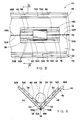
- Fig. 3 is an enlarged side elevational view of a pellet guide chute assembly, a pellet position sensing arrangement and an ultrasonic inspection head for modifing the prior art inspection apparatus of Fig. 1 for inspection of nuclear fuel pellets.
- Fig. 4 is a perspective view of the pellet guide chute assembly of Fig. 3, being shown in exploded, unassembled form.
- Fig. 5 is another perspective view similar to that of Fig. 4, except showing the guide chute assembly in assembled form.
- Figs. 6 and 7 are end views of the chute of Fig. 5, showing a pair of adjustable plates of the guide chute assembly at different locations on a support substrate thereof for positioning pellets of different diameters for inspection.
- Fig. 8 is a fragmentary top plan view of the chute of Fig. 5, showing a pellet in an inspection chamber.
- Fig. 9 is a cross-sectional view of the guide chute assembly taken along
line 9--9 of Fig. 8. - Fig. 10 is a perspective view of a cover for use on the guide chute assembly of Fig. 8 over the inspection chamber.
- Fig. 11 is an enlarged top plan view of the guide chute assembly cover of Fig. 10.
- Fig. 12 is another top plan view similar to that of Fig. 8, with the cover of Fig. 10 mounted thereon.
- Fig. 13 is a cross-sectional view of the covered chute taken along
line 13--13 of Fig. 12. - Fig. 14 is a side elevational view of the ultrasonic inspection head of Fig. 3.
- Fig. 15 is a top plan view of the ultrasonic inspection head as seen along line 15--15 of Fig. 14.
- Fig. 16 is a bottom plan view of the ultrasonic inspection head as seen along
line 16--16 of Fig. 14. - In the following description, like reference characters designate like or corresponding parts throughout the several views of the drawings. Also in the following description, it is to be understood that such terms as "forward", "rearward", "left", "right", "upwardly", "downwardly", and the like, are words of convenience and are not to be construed as limiting terms.
- Referring now to the drawings, and particularly to Figs. 1 and 2, there is shown a prior art inspection apparatus, being generally designated by the
numeral 10 and sold by Cochlea Corporation, for inspecting the shapes of small parts and sorting parts with good shapes from those with bad ones. In its basic arrangement, theinspection apparatus 10 includes awheeled base 12 and aconsole 14, a built-in microprocessor-based computer system (not shown) and video display terminal (VDT)keyboard 16 andVDT monitor 18 mounted on thebase 12. - Also, the prior
art inspection apparatus 10 includes aninspection chamber 20 having an ultrasonic inspection head 22 (Figs. 14-16), a heated air system (not shown) for maintaining theinspection chamber 20 andhead 22 in the desired operating temperature range. Further, theinspection apparatus 10 includes an inclined inspection track orchute 24 upon which parts are fed from avibratory bowl feeder 26 by asingulation device 28. The parts slide in single file fashion down thechute 24 under the influence of gravity past theinspection head 22. At the lower end of thechute 24 is positioned two bins, onebin 30 for good parts and onebin 32 for bad parts, and aflipper device 34 being operable for directing the parts to the correct one of thebins - In operation, the prior
art inspection apparatus 10 carries out acoustical inspection of the shapes of the parts one at a time as they pass through theinspection chamber 20. Basically, the computer system of theinspection apparatus 10 is taught the shape and orientation of a part having the desired or optimum configuration or shape during an initial "learn mode." Sound waves reflected from any subsequent part being inspected are received by an array of transducers 36 making up theultrasonic inspection head 22. One of thetransducers 36A transmits sound waves, whereas the rest of thetransducers 36B receive the reflected sound waves. - Based on these reflected sound waves, the
receiving transducers 36B of theinspection head 22 generate an "acoustic signature" of the part. The microprocessor-based computer system interprets these signatures. Each part thus generates a unique signature and only parts identical to those programmed in the "learn mode" can create the same signature. Defect-free parts are thus determined by comparing the acoustic signatures of parts being inspected to the signatures generated earlier as during the "learn mode." Parts whose signatures do not conform to the "learned" signature are rejected as defective and diverted by theflipper 34 into thebad parts bin 32. Good parts are not diverted and go into thegood parts bin 30. - The details of how part shape is acoustically detected by the
inspection head 22 and analyzed by the computer system of the priorart inspection apparatus 10 need not be described herein in any greater detail since the modifications made to theprior art apparatus 10 in accordance with the principles of the present invention to adapt it for use in inspecting nuclear fuel pellets do not relate to such details. In fact, the modified apparatus operates in this regard the same as the priorart inspection apparatus 10 sold by Cochlea Corporation. Therefore, further description of these details would not contribute to gaining a thorough understanding of the improvements of the present invention which will be described below. Reference can be made to the above-cited U.S. patents assigned to Cochlea Corporation and to the Inspector General User's Guide for gaining a detailed description of such details. - In place of the
vibratory bowl feeder 26, theinspection chute 24, theflipper device 34, and the good andbad parts bins art inspection apparatus 10 is modified in accordance with the principles of the present invention to adapt it to inspectnuclear fuel pellets 38 by substituting a single pellet feeder, a pelletguide chute assembly 40 and a pellet discharge conveyor. The single pellet feeder and pellet discharge conveyor which do not form part of the present invention need not be illustrated and described herein to gain a complete and thorough understanding of the improvements provided by the present invention. In operation, a modified inspection apparatus using most of the earlier-described prior art components in conjunction with these improved substituted ones can carry out acoustical inspection ofnuclear fuel pellets 12 one at a time for circumferential or surface defects, such as chips and cracks. - As seen generally in Fig. 3, the improvements incorporated by the modified inspection apparatus basically relate to the pellet guide chute assembly 40 (see also Figs. 4-9) disposed in an inclined fashion (similar to the prior art inspection chute 24), and to a cover 42 (see also Figs. 10 to 12) overlying the
chute assembly 40 at theinspection chamber 20 adjacent theinspection head 22 and a pellet position sensing arrangement 44 (see also Fig. 13) being positioned at theinspection chamber 20 and theinspection head 22 along thechute assembly 40. - Referring now to Figs. 4 to 9, there is shown the pellet
guide chute assembly 40 in greater detail. Theguide chute assembly 40 as before is inclined and extends through theinspection chamber 20. In its basic components, theguide chute assembly 40 includes asupport substrate 46 composed of a pair ofelongated wall sections elongated plates - More particularly, the
wall sections chute assembly substrate 40 each have a pair of opposite spacedlongitudinal edges wall sections adjacent ones corner 56 and are angularly displaced from one another at outer orremote ones substrate 40 with a generally ninety-degree, V-shaped configuration in cross section. Theplates substrate wall sections nuclear fuel pellet 38 between and on adjacentlongitudinal portions inspection chamber 20. - Still further, the
plates slots cutout regions pellet 38 at the respective adjacentlongitudinal portions slots cutout regions plates upper side portions interior corner portion 56A of the supportsubstrate wall sections inspection chamber 20 such that acoustical energy can be propagated to and from bottom and side portions 38A, 38B of thepellet 38 resting adjacent the respectivelongitudinal portions corner portions - The
respective cutout regions adjacent ones plates longitudinal portions respective slots cutout regions remote ones slots cutout regions respective plates ligaments plates longitudinal plate portions pellet 38 rests, as can be seen in Figs. 8 and 9. - Figs. 6 to 9 also illustrate means for adjustably attaching the
plates substrate wall sections longitudinal edges wall sections plates ligaments longitudinal portions inspection chamber 20 of the modified inspection apparatus. Specifically, lateral movement of theplates ligaments pellets 38 having different diameters. - More particularly, the attaching means of the
guide chute assembly 40 for adjustably attaching theplates wall sections support substrate 46 include a plurality ofelongated holes 70 in the form of elongated slots defined through theplates removable fasteners 72 inserted through theholes 70 and threadably anchored to thewall sections fasteners 72 can be turned to partially unthread them from thewall sections plates plates fasteners 72 are retightened to reattach the plates at the desired stationary positions on the supportsubstrate wall sections - Also, in the modified inspection apparatus, the
cover 42 has a planarcentral section 42A and opposite downturnedopposite edges guide chute assembly 40 at theinspection chamber 20. Thecover 42 provides a means for reflecting and confining the acoustical energy within the inspection chamber. Thecover 42 contains a plurality of openings in the form ofelongated slots 74 defined through thecover 42 so as to extend generally parallel to one another and generally perpendicular to a longitudinal path of sliding movement of thepellet 38 down theinclined chute assembly 40 through theinspection chamber 20. Thecover 42 also has an opening or notch 76 defined therethrough which receives theultrasonic inspection head 22 having ahousing 22A mounting the acoustical energy transmitting and receivingtransducers inspection chamber 20 for propagating such energy to and from thepellet 38 therein. - The pellet
position sensing arrangement 44 of the modified inspection apparatus is associated with thesupport substrate 46 and thecover 42 at theinspection chamber 20 for sensing the position of thepellet 38 as the same slides under the influence of gravity down the inclinedguide chute assembly 40 along the longitudinal path through the inspection chamber. Specifically, thesupport substrate 46 has an elongated opening or slit 78 defined therethrough at itscorner 56 and being aligned with thecutout regions plates pellet 38 through theinspection chamber 20. As mentioned above, theslots 74 in thecover 42 are spaced apart along longitudinal path of the pellet through theinspection chamber 20. - The pellet
position sensing arrangement 44 includes alight transmitting device 80 disposed at the exterior of thesubstrate corner 56 and aligned withelongated slit 78 therethrough for transmitting light through the open slit and across theinspection chamber 20. Thearrangement 44 also includes a plurality oflight receiving devices 82 disposed at the exterior of thecover 42 and aligned with therespective slots 74 therethrough for receiving light transmitted through thecover slots 74 from across theinspection chamber 20 by thelight transmitting device 80. - As mentioned above, the elongated substrate slit 78 is defined through the
corner 56 of thesubstrate 46 formed by the rigidly attachedwall sections interior corner portion 56A exposed by theadjacent cutout regions plates substrate 46. The elongated slit also underlies the bottom of thepellet 38 being supported between the adjacentlongitudinal portions plates light transmitting device 80 to thelight receiving devices 82 is interrupted by thepellet 38 as the latter slides alons its longitudinal path between thedevices - It is thought that the present invention and many of its attendant advantages will be understood from the foregoing description and it will be apparent that various changes may be made in the form, construction and arrangement thereof without departing from the spirit and scope of the invention.
Claims (12)
a) an inspection chamber (20)
b) a pellet guide chute (40) extending through said inspection chamber (20), and
c) ultrasonic transducer means (22) for transmitting and receiving acoustical energy into and from said inspection chamber (20),
characterized in that
said cover (420) has a plurality of openings (74) defined therethrough in spaced appart relation along said path of the pellet (38) through said inspection chamber (20); and
said arrangement (44) includes light transmitting means (80) disposed at the exterior of said substrate (46) and aligned with said elongated opening (78) therethrough for transmitting light through said opening (78) and across said inspection chamber (20), and light receiving means (82) disposed at the exterior of said cover (42) and aligned with said openings (74) therethrough for receiving light transmitted through said cover openings (74) from across said inspection chamber (20) by said light transmitting means (80).
Applications Claiming Priority (2)
| Application Number | Priority Date | Filing Date | Title |
|---|---|---|---|
| US199735 | 1988-05-27 | ||
| US07/199,735 US4894201A (en) | 1988-05-27 | 1988-05-27 | Nuclear fuel pellet surface defect inspection apparatus |
Publications (3)
| Publication Number | Publication Date |
|---|---|
| EP0343411A2 true EP0343411A2 (en) | 1989-11-29 |
| EP0343411A3 EP0343411A3 (en) | 1990-12-05 |
| EP0343411B1 EP0343411B1 (en) | 1994-03-02 |
Family
ID=22738793
Family Applications (1)
| Application Number | Title | Priority Date | Filing Date |
|---|---|---|---|
| EP89108148A Expired - Lifetime EP0343411B1 (en) | 1988-05-27 | 1989-05-05 | Nuclear fuel pellet surface defect inspection apparatus |
Country Status (6)
| Country | Link |
|---|---|
| US (1) | US4894201A (en) |
| EP (1) | EP0343411B1 (en) |
| JP (1) | JP2646264B2 (en) |
| KR (1) | KR890017717A (en) |
| DE (1) | DE68913347D1 (en) |
| ES (1) | ES2049274T3 (en) |
Cited By (1)
| Publication number | Priority date | Publication date | Assignee | Title |
|---|---|---|---|---|
| EP0593156A1 (en) * | 1992-08-19 | 1994-04-20 | Mitsubishi Nuclear Fuel Co. | Installation for handling, arranging and sorting short cylindrical bodies, such as nuclear fuel pellets |
Families Citing this family (10)
| Publication number | Priority date | Publication date | Assignee | Title |
|---|---|---|---|---|
| US4978495A (en) * | 1988-05-27 | 1990-12-18 | Westinghouse Electric Corp. | Nuclear fuel pellet surface defect inspection apparatus |
| US4960559A (en) * | 1989-05-17 | 1990-10-02 | Westinghouse Electric Corp. | Capture row storage tray for holding collated rows of nuclear fuel pellets |
| US5156802A (en) * | 1991-03-15 | 1992-10-20 | The Babcock & Wilcox Company | Inspection of fuel particles with acoustics |
| ES2042408A2 (en) * | 1991-04-05 | 1993-12-01 | Westinghouse Electric Corp | Assembly for sliding and inspecting pellets in an apparatus for inspecting surface defects in nuclear-fuel pellets |
| US5207976A (en) * | 1991-04-05 | 1993-05-04 | Westinghouse Electric Corp. | Pellet slide and inspection assembly in a nuclear fuel pellet surface defect inspection apparatus |
| US5213218A (en) * | 1991-08-05 | 1993-05-25 | Westinghouse Electric Corp. | Pellet reject apparatus and method |
| US5696326A (en) * | 1993-12-20 | 1997-12-09 | Axis Usa, Inc. | Method and apparatus for acoustic testing of armatures |
| US6786096B2 (en) | 2001-11-28 | 2004-09-07 | Battelle Memorial Institute | System and technique for detecting the presence of foreign material |
| US6992771B2 (en) * | 2001-11-28 | 2006-01-31 | Battelle Memorial Institute | Systems and techniques for detecting the presence of foreign material |
| US20050174567A1 (en) * | 2004-02-09 | 2005-08-11 | Mectron Engineering Company | Crack detection system |
Citations (4)
| Publication number | Priority date | Publication date | Assignee | Title |
|---|---|---|---|---|
| GB1102940A (en) * | 1964-12-28 | 1968-02-14 | Combustion Eng | Ultrasonic flaw detecting method and apparatus |
| FR1580157A (en) * | 1967-02-08 | 1969-09-05 | ||
| US3672211A (en) * | 1970-06-01 | 1972-06-27 | Automation Ind Inc | Ultrasonic search unit |
| US4677852A (en) * | 1985-09-27 | 1987-07-07 | Cochlea Corporation | Method of and apparatus for inspecting and/or positioning objects with wave energy using wave guides |
Family Cites Families (22)
| Publication number | Priority date | Publication date | Assignee | Title |
|---|---|---|---|---|
| US2635746A (en) * | 1949-06-25 | 1953-04-21 | Electronic Associates | Testing and sorting control system |
| NL96598C (en) * | 1954-12-16 | |||
| US3029943A (en) * | 1955-09-09 | 1962-04-17 | Gen Motors Corp | Electronic flaw detectro |
| GB898080A (en) * | 1959-04-08 | 1962-06-06 | Kelvin & Hughes Ltd | Improvements in and relating to ultrasonic testing of material |
| GB992812A (en) * | 1961-03-14 | 1965-05-19 | Nuclear Materials & Equipment | Continuous object processing apparatus |
| CA944845A (en) * | 1970-11-05 | 1974-04-02 | Colonial Sugar Refining Company Limited (The) | High speed sorting |
| US3907123A (en) * | 1973-05-31 | 1975-09-23 | Exxon Nuclear Co Inc | Fuel rod pellet loading head |
| US3975261A (en) * | 1974-01-02 | 1976-08-17 | Tac Technical Instrument Corporation | Sequential event memory circuit for process and quality control |
| US3969228A (en) * | 1974-12-30 | 1976-07-13 | Browning Gordon D | Quality control monitor |
| US4037103A (en) * | 1975-08-07 | 1977-07-19 | Exxon Research And Engineering Company | Diameter measuring system for cylindrical objects |
| US4193502A (en) * | 1977-04-29 | 1980-03-18 | Westinghouse Electric Corp. | Pellet dimension checker |
| SE409627B (en) * | 1978-01-24 | 1979-08-27 | Asea Atom Ab | METHODS OF FITTING FUEL PADS IN ENCLOSURE PIPES IN THE MANUFACTURE OF NUCLEAR FUEL RODS AND EQUIPMENT FOR PERFORMING THE KIT |
| US4212398A (en) * | 1978-08-16 | 1980-07-15 | Pet Incorporated | Particle separating device |
| US4208915A (en) * | 1979-01-31 | 1980-06-24 | Edwards Bill R | Method of determining foreign material in food products using ultrasonic sound |
| US4268808A (en) * | 1979-05-21 | 1981-05-19 | Massachusetts Institute Of Technology | Acoustic wave device |
| US4349112A (en) * | 1980-03-31 | 1982-09-14 | The United States Of America As Represented By The United States Department Of Energy | Pellet inspection apparatus |
| US4468163A (en) * | 1982-03-25 | 1984-08-28 | General Electric Company | Tray loader method and apparatus for nuclear fuel pellets |
| US4557386A (en) * | 1983-06-27 | 1985-12-10 | Cochlea Corporation | System to measure geometric and electromagnetic characteristics of objects |
| US4576286A (en) * | 1983-06-27 | 1986-03-18 | Cochlea Corporation | Parts sorting systems |
| US4628736A (en) * | 1985-01-14 | 1986-12-16 | Massachusetts Institute Of Technology | Method and apparatus for measurement of ice thickness employing ultra-sonic pulse echo technique |
| US4690284A (en) * | 1985-10-04 | 1987-09-01 | Cochlea Corporation | Method of and apparatus for inspecting objects using multiple position detectors |
| US4819783A (en) * | 1986-07-29 | 1989-04-11 | Cochlea Corporation | Automated inspection system and method |
-
1988
- 1988-05-27 US US07/199,735 patent/US4894201A/en not_active Expired - Fee Related
-
1989
- 1989-05-05 EP EP89108148A patent/EP0343411B1/en not_active Expired - Lifetime
- 1989-05-05 ES ES89108148T patent/ES2049274T3/en not_active Expired - Lifetime
- 1989-05-05 DE DE89108148T patent/DE68913347D1/en not_active Expired - Lifetime
- 1989-05-26 JP JP1131702A patent/JP2646264B2/en not_active Expired - Lifetime
- 1989-05-26 KR KR1019890007098A patent/KR890017717A/en not_active Application Discontinuation
Patent Citations (4)
| Publication number | Priority date | Publication date | Assignee | Title |
|---|---|---|---|---|
| GB1102940A (en) * | 1964-12-28 | 1968-02-14 | Combustion Eng | Ultrasonic flaw detecting method and apparatus |
| FR1580157A (en) * | 1967-02-08 | 1969-09-05 | ||
| US3672211A (en) * | 1970-06-01 | 1972-06-27 | Automation Ind Inc | Ultrasonic search unit |
| US4677852A (en) * | 1985-09-27 | 1987-07-07 | Cochlea Corporation | Method of and apparatus for inspecting and/or positioning objects with wave energy using wave guides |
Cited By (2)
| Publication number | Priority date | Publication date | Assignee | Title |
|---|---|---|---|---|
| EP0593156A1 (en) * | 1992-08-19 | 1994-04-20 | Mitsubishi Nuclear Fuel Co. | Installation for handling, arranging and sorting short cylindrical bodies, such as nuclear fuel pellets |
| US5323433A (en) * | 1992-08-19 | 1994-06-21 | Asahi Kogaku Kogyo Kabushiki Kaisha | Apparatus for arranging short cylindrical bodies |
Also Published As
| Publication number | Publication date |
|---|---|
| DE68913347D1 (en) | 1994-04-07 |
| KR890017717A (en) | 1989-12-18 |
| EP0343411B1 (en) | 1994-03-02 |
| JPH0225746A (en) | 1990-01-29 |
| JP2646264B2 (en) | 1997-08-27 |
| EP0343411A3 (en) | 1990-12-05 |
| ES2049274T3 (en) | 1994-04-16 |
| US4894201A (en) | 1990-01-16 |
Similar Documents
| Publication | Publication Date | Title |
|---|---|---|
| EP0343411B1 (en) | Nuclear fuel pellet surface defect inspection apparatus | |
| US5515298A (en) | Apparatus for determining surface structures | |
| JP3816563B2 (en) | Method and apparatus for mechanically measuring thickness and / or basis weight of moving material under test | |
| RU2444010C2 (en) | Apparatus for emitting and/or receiving ultrasound and ultrasonic sensor for analysing valuable document | |
| US4307292A (en) | Marksmanship training apparatus | |
| US7328619B2 (en) | Phased array ultrasonic NDT system for fastener inspections | |
| US20100218589A1 (en) | Method for Configuring an Array of Transducers in an Ultrasonic Test Apparatus | |
| US6718008B1 (en) | X-ray diffraction screening system with retractable x-ray shield | |
| JPH06502250A (en) | Ultrasonic method and device for measuring the outer diameter of tubes | |
| US4978495A (en) | Nuclear fuel pellet surface defect inspection apparatus | |
| JP4791489B2 (en) | Ultrasonic beam forming device | |
| CN106124625B (en) | Air Coupling ultrasonic wave high energy detection method and system | |
| JPS59214793A (en) | Method and device for detecting failure of fuel element | |
| US9404897B2 (en) | Method for the non-destructive inspection of a test object of great material thickness by means of ultrasound, the use of a test probe for carrying out the method, an ultrasonic test probe, a control unit for an ultrasonic test probe and a device for the non-destructive inspection of a test object of great material thickness by means of ultrasound | |
| JP4564867B2 (en) | Ultrasonic flaw detection method and apparatus | |
| KR100602769B1 (en) | A reference block for ultrasonic testing | |
| US5207976A (en) | Pellet slide and inspection assembly in a nuclear fuel pellet surface defect inspection apparatus | |
| EP0246711A2 (en) | A device for recognising the shape and dimension of bottles or the like | |
| JP2005315793A (en) | Hardness measuring apparatus | |
| JPH04166761A (en) | Ultrasonic probe | |
| CN116297857A (en) | Ultrasonic phased array detection method for in-service fork lugs of suspension bridge slings | |
| EP0620434A1 (en) | Ultrasonic transducer | |
| SU1288590A1 (en) | Piezoelectric transducer for ultrasonic checking | |
| JPH044220Y2 (en) | ||
| JPH1082769A (en) | Adjustable focusing probe |
Legal Events
| Date | Code | Title | Description |
|---|---|---|---|
| PUAI | Public reference made under article 153(3) epc to a published international application that has entered the european phase |
Free format text: ORIGINAL CODE: 0009012 |
|
| AK | Designated contracting states |
Kind code of ref document: A2 Designated state(s): BE DE ES FR GB IT SE |
|
| PUAL | Search report despatched |
Free format text: ORIGINAL CODE: 0009013 |
|
| AK | Designated contracting states |
Kind code of ref document: A3 Designated state(s): BE DE ES FR GB IT SE |
|
| 17P | Request for examination filed |
Effective date: 19910102 |
|
| 17Q | First examination report despatched |
Effective date: 19920908 |
|
| GRAA | (expected) grant |
Free format text: ORIGINAL CODE: 0009210 |
|
| AK | Designated contracting states |
Kind code of ref document: B1 Designated state(s): BE DE ES FR GB IT SE |
|
| PG25 | Lapsed in a contracting state [announced via postgrant information from national office to epo] |
Ref country code: SE Free format text: THE PATENT HAS BEEN ANNULLED BY A DECISION OF A NATIONAL AUTHORITY Effective date: 19940302 Ref country code: DE Effective date: 19940302 Ref country code: BE Effective date: 19940302 Ref country code: FR Free format text: THE PATENT HAS BEEN ANNULLED BY A DECISION OF A NATIONAL AUTHORITY Effective date: 19940302 Ref country code: IT Free format text: LAPSE BECAUSE OF FAILURE TO SUBMIT A TRANSLATION OF THE DESCRIPTION OR TO PAY THE FEE WITHIN THE PRE;WARNING: LAPSES OF ITALIAN PATENTS WITH EFFECTIVE DATE BEFORE 2007 MAY HAVE OCCURRED AT ANY TIME BEFORE 2007. THE CORRECT EFFECTIVE DATE MAY BE DIFFERENT FROM THE ONE RECORDED.SCRIBED TIME-LIMIT Effective date: 19940302 |
|
| REF | Corresponds to: |
Ref document number: 68913347 Country of ref document: DE Date of ref document: 19940407 |
|
| REG | Reference to a national code |
Ref country code: ES Ref legal event code: FG2A Ref document number: 2049274 Country of ref document: ES Kind code of ref document: T3 |
|
| PG25 | Lapsed in a contracting state [announced via postgrant information from national office to epo] |
Ref country code: GB Effective date: 19940602 |
|
| EN | Fr: translation not filed | ||
| PLBE | No opposition filed within time limit |
Free format text: ORIGINAL CODE: 0009261 |
|
| STAA | Information on the status of an ep patent application or granted ep patent |
Free format text: STATUS: NO OPPOSITION FILED WITHIN TIME LIMIT |
|
| GBPC | Gb: european patent ceased through non-payment of renewal fee |
Effective date: 19940602 |
|
| 26N | No opposition filed | ||
| PGFP | Annual fee paid to national office [announced via postgrant information from national office to epo] |
Ref country code: ES Payment date: 20080416 Year of fee payment: 20 |
|
| REG | Reference to a national code |
Ref country code: ES Ref legal event code: FD2A Effective date: 20090506 |
|
| PG25 | Lapsed in a contracting state [announced via postgrant information from national office to epo] |
Ref country code: ES Free format text: LAPSE BECAUSE OF EXPIRATION OF PROTECTION Effective date: 20090506 |