EP0343315A2 - Break away tool element and method of mounting - Google Patents
Break away tool element and method of mounting Download PDFInfo
- Publication number
- EP0343315A2 EP0343315A2 EP89100091A EP89100091A EP0343315A2 EP 0343315 A2 EP0343315 A2 EP 0343315A2 EP 89100091 A EP89100091 A EP 89100091A EP 89100091 A EP89100091 A EP 89100091A EP 0343315 A2 EP0343315 A2 EP 0343315A2
- Authority
- EP
- European Patent Office
- Prior art keywords
- plate
- assembly
- support
- tool
- tool element
- Prior art date
- Legal status (The legal status is an assumption and is not a legal conclusion. Google has not performed a legal analysis and makes no representation as to the accuracy of the status listed.)
- Granted
Links
- 238000000034 method Methods 0.000 title claims description 9
- 230000033001 locomotion Effects 0.000 claims description 19
- 230000020347 spindle assembly Effects 0.000 claims description 8
- 229910001220 stainless steel Inorganic materials 0.000 claims description 2
- 239000010935 stainless steel Substances 0.000 claims description 2
- 238000006073 displacement reaction Methods 0.000 claims 2
- 239000000463 material Substances 0.000 claims 2
- 230000011664 signaling Effects 0.000 claims 1
- 230000007246 mechanism Effects 0.000 description 6
- 230000009471 action Effects 0.000 description 3
- 239000000314 lubricant Substances 0.000 description 2
- 230000008569 process Effects 0.000 description 2
- XLYOFNOQVPJJNP-UHFFFAOYSA-N water Substances O XLYOFNOQVPJJNP-UHFFFAOYSA-N 0.000 description 2
- 230000006978 adaptation Effects 0.000 description 1
- 230000000712 assembly Effects 0.000 description 1
- 238000000429 assembly Methods 0.000 description 1
- 230000006835 compression Effects 0.000 description 1
- 238000007906 compression Methods 0.000 description 1
- 238000005520 cutting process Methods 0.000 description 1
- 230000000694 effects Effects 0.000 description 1
- 230000004807 localization Effects 0.000 description 1
- 230000007257 malfunction Effects 0.000 description 1
- 238000012986 modification Methods 0.000 description 1
- 230000004048 modification Effects 0.000 description 1
Images


Classifications
-
- B—PERFORMING OPERATIONS; TRANSPORTING
- B23—MACHINE TOOLS; METAL-WORKING NOT OTHERWISE PROVIDED FOR
- B23Q—DETAILS, COMPONENTS, OR ACCESSORIES FOR MACHINE TOOLS, e.g. ARRANGEMENTS FOR COPYING OR CONTROLLING; MACHINE TOOLS IN GENERAL CHARACTERISED BY THE CONSTRUCTION OF PARTICULAR DETAILS OR COMPONENTS; COMBINATIONS OR ASSOCIATIONS OF METAL-WORKING MACHINES, NOT DIRECTED TO A PARTICULAR RESULT
- B23Q5/00—Driving or feeding mechanisms; Control arrangements therefor
- B23Q5/54—Arrangements or details not restricted to group B23Q5/02 or group B23Q5/22 respectively, e.g. control handles
- B23Q5/58—Safety devices
-
- B—PERFORMING OPERATIONS; TRANSPORTING
- B23—MACHINE TOOLS; METAL-WORKING NOT OTHERWISE PROVIDED FOR
- B23Q—DETAILS, COMPONENTS, OR ACCESSORIES FOR MACHINE TOOLS, e.g. ARRANGEMENTS FOR COPYING OR CONTROLLING; MACHINE TOOLS IN GENERAL CHARACTERISED BY THE CONSTRUCTION OF PARTICULAR DETAILS OR COMPONENTS; COMBINATIONS OR ASSOCIATIONS OF METAL-WORKING MACHINES, NOT DIRECTED TO A PARTICULAR RESULT
- B23Q1/00—Members which are comprised in the general build-up of a form of machine, particularly relatively large fixed members
- B23Q1/25—Movable or adjustable work or tool supports
- B23Q1/44—Movable or adjustable work or tool supports using particular mechanisms
- B23Q1/50—Movable or adjustable work or tool supports using particular mechanisms with rotating pairs only, the rotating pairs being the first two elements of the mechanism
- B23Q1/52—Movable or adjustable work or tool supports using particular mechanisms with rotating pairs only, the rotating pairs being the first two elements of the mechanism a single rotating pair
-
- Y—GENERAL TAGGING OF NEW TECHNOLOGICAL DEVELOPMENTS; GENERAL TAGGING OF CROSS-SECTIONAL TECHNOLOGIES SPANNING OVER SEVERAL SECTIONS OF THE IPC; TECHNICAL SUBJECTS COVERED BY FORMER USPC CROSS-REFERENCE ART COLLECTIONS [XRACs] AND DIGESTS
- Y10—TECHNICAL SUBJECTS COVERED BY FORMER USPC
- Y10S—TECHNICAL SUBJECTS COVERED BY FORMER USPC CROSS-REFERENCE ART COLLECTIONS [XRACs] AND DIGESTS
- Y10S248/00—Supports
- Y10S248/90—Movable or disengageable on impact or overload
-
- Y—GENERAL TAGGING OF NEW TECHNOLOGICAL DEVELOPMENTS; GENERAL TAGGING OF CROSS-SECTIONAL TECHNOLOGIES SPANNING OVER SEVERAL SECTIONS OF THE IPC; TECHNICAL SUBJECTS COVERED BY FORMER USPC CROSS-REFERENCE ART COLLECTIONS [XRACs] AND DIGESTS
- Y10—TECHNICAL SUBJECTS COVERED BY FORMER USPC
- Y10S—TECHNICAL SUBJECTS COVERED BY FORMER USPC CROSS-REFERENCE ART COLLECTIONS [XRACs] AND DIGESTS
- Y10S408/00—Cutting by use of rotating axially moving tool
- Y10S408/71—Safety device
-
- Y—GENERAL TAGGING OF NEW TECHNOLOGICAL DEVELOPMENTS; GENERAL TAGGING OF CROSS-SECTIONAL TECHNOLOGIES SPANNING OVER SEVERAL SECTIONS OF THE IPC; TECHNICAL SUBJECTS COVERED BY FORMER USPC CROSS-REFERENCE ART COLLECTIONS [XRACs] AND DIGESTS
- Y10—TECHNICAL SUBJECTS COVERED BY FORMER USPC
- Y10T—TECHNICAL SUBJECTS COVERED BY FORMER US CLASSIFICATION
- Y10T409/00—Gear cutting, milling, or planing
- Y10T409/30—Milling
- Y10T409/30392—Milling with means to protect operative or machine [e.g., guard, safety device, etc.]
-
- Y—GENERAL TAGGING OF NEW TECHNOLOGICAL DEVELOPMENTS; GENERAL TAGGING OF CROSS-SECTIONAL TECHNOLOGIES SPANNING OVER SEVERAL SECTIONS OF THE IPC; TECHNICAL SUBJECTS COVERED BY FORMER USPC CROSS-REFERENCE ART COLLECTIONS [XRACs] AND DIGESTS
- Y10—TECHNICAL SUBJECTS COVERED BY FORMER USPC
- Y10T—TECHNICAL SUBJECTS COVERED BY FORMER US CLASSIFICATION
- Y10T82/00—Turning
- Y10T82/25—Lathe
- Y10T82/2552—Headstock
-
- Y—GENERAL TAGGING OF NEW TECHNOLOGICAL DEVELOPMENTS; GENERAL TAGGING OF CROSS-SECTIONAL TECHNOLOGIES SPANNING OVER SEVERAL SECTIONS OF THE IPC; TECHNICAL SUBJECTS COVERED BY FORMER USPC CROSS-REFERENCE ART COLLECTIONS [XRACs] AND DIGESTS
- Y10—TECHNICAL SUBJECTS COVERED BY FORMER USPC
- Y10T—TECHNICAL SUBJECTS COVERED BY FORMER US CLASSIFICATION
- Y10T82/00—Turning
- Y10T82/25—Lathe
- Y10T82/2564—Tailstock
Definitions
- a conventional machine tool has a base to which is secured a spindle which rotates the workpiece.
- the machine may have a tailstock to maintain the workpiece in proper alignment as the workpiece is operated upon by a tool.
- the tool is typically mounted to a turret which is movable relative to the spindle through a cross-slide. The turret may move parallel to the axis of the workpiece and/or transverse thereto. Proper operation of the machine tool requires that the various elements cooperate in a manner which assures good part repeatability.
- the tailstock and turret are, as noted, movable both toward and away from the spindle. Additionally, the turret is movable toward the tailstock, thereby presenting the possibility of contacting the tailstock should the machine be improperly programmed or should a malfunction occur.
- the disclosed invention is a method of mounting a tool element in order to prevent damage to the linear ways by permitting the tailstock or other such tool element to move relative to those ways, and to be replaced rapidly and in accurate alignment.
- the primary object of the disclosed invention is a break away machine tool assembly and method of mounting which prevents damage to the machine tool ways and which permits the tailstock or other similar tool element to be rapidly repositioned and accurately aligned in order to avoid excessive down time while assuring good part repeatability.
- a break away machine tool assembly comprises a support.
- a bearing plate overlies the support and is contiguous thereto and is movable relative thereto.
- a tool element overlies and is contiguous the plate and is movable therewith.
- Means releasably secure the plate and the element in overlying relation to the support for permitting the plate and the element to move relative to the support within a defined range upon being subjected to an impact.
- a machine tool assembly comprises a base to which a headstock is mounted at one end thereof and the headstock includes means rotatable on a first axis for gripping and releasing work.
- a first tool element is displaceably mounted to the base and includes a work engaging portion coaxial with the first axis and the first tool element is movable on a second axis parallel to the first axis.
- a second tool element is displaceably mounted to the base and includes a work engaging portion. The second tool element is movable on a third axis parallel to the first axis and also on a fourth axis generally transverse to the first axis.
- the first tool element includes a support, a bearing plate overlying and contiguous the support, tool means overlying and contiguous the plate, and means releaseably secure the plate and the tool means in overlying relation to the support for permitting the plate and the tool means to move relative to the support within a defined range upon the first and second tool elements contacting each other.
- the method of mounting a machine tool tool element to prevent damage to the ways comprises the steps of providing a support movable along the machine tool base. Overlying the support is a bearing plate which is also contiguous therewith. Overlying the bearing plate and contiguous therewith is a tool element. Securing the bearing plate and tool element to the support is accomplished through releaseable securing means which permit the bearing plate and the tool element to move relative to the support within a defined range upon the plate and the tool element being subjected to impact.
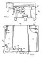
- Machine tool M as best shown in Figure 1, includes a base B to one end of which headstock H is mounted.
- Headstock H include a spindle assembly S with a rotary work holder, such as collet 10.
- the base B may, in certain instances, be disposed at a substantial angle to the horizontal in order to permit cuttings and the like to slide along the base B in order to facilitate removal.
- Turret assembly T is movably mounted on cross-slide C.
- the cross-slide C include telescoping means 12 permitting the turret assembly T to move generally transverse to the axis of collet 10 and furthermore includes telescoping means 14 permitting movement parallel to the axis of collet 10.
- the turret assembly T has a motor 16 to which indexable tool holding head 18 is mounted.
- the head 18 carries a number of tools 20 in order to permit a piece of work rotated by the collet 10 to be operated on, and to thereby achieve a desired shape, configuration or the like.
- the motion of the turret assembly T parallel and transverse to the axis of the collet 10 permits the tools 20 to be moved longitudinally and transversely of the workpiece.
- Tailstock 22 is similarly mounted to base B for reciprocation toward and away from collet 10.
- the tailstock 22 has a work engaging portion 24 which is coaxial with the axis of rotation of collet 10.
- the tailstock 22 is movable upon spaced parallel ways 26 and 28, as best shown in Figure 2.
- the ways 26 and 28 permit rapid movement of the tailstock 22 toward and away from the collet 10.
- the ways 26 and 28 must remain in proper longitudinal spaced parallel alignment in order to permit rapid movement to occur.
- way cover systems 30 and 32 are operably connected to and movable with tailstock 22 and extend therefrom for overlying and protecting ways 26 and 28. In this way, dirt, debris and the like cannot contaminate the ways 26 and 28.
- each of the way cover systems 30 and 32 comprises a plurality of U-shaped covers 34 which are nestled one in another in order to achieve a telescopic action as the tailstock 22 moves.
- Support 36 is secured to way cover systems 30 and 32.
- Bearing plate 38 overlies and is contiguous with support 36.
- the bearing plate 38 is, preferably, comprised of stainless steel and a non-water soluble lubricant is disposed between the plate 38 and the support 36 in order to prevent galling and to permit movement of the plate 38 relative to the support 36.
- the tailstock 22 has a base portion 40 which overlies and is contiguous with plate 38.
- a non-water soluble lubricant is disposed between the base portion 40 and the plate 38 for like reasons.
- the plate 38 has a pair of oval slots 42 and 44 which are juxtaposed one to the other with slots 43 and 45 in the support 36, respectively, as best shown in Figure 11.
- the slots 42 and 44 are aligned with the slots 43 and 45 when the tailstock 22 is in the operating configuration of Figure 1.
- the support 36 and the plate 38 also have aligned openings 88 and 46 in one corner thereof, as best shown in Figure 7.
- the slots 42, 43 and 44, 45 are disposed adjacent forward edge 48.
- Each of the slots 42, 43 and 44, 45 is angularly offset from the edge 48 in order to facilitate pivoting of the plate 38 around the openings 46 and 88.
- the slots 44 and 45 are at a sharper angle to the edge 48 than are the slots 42 and 43 because the slots 44 and 45 are at a greater distance from the pivot axis defined by the openings 46 and 88 than are the slots 42 and 43.
- Figures 3 and 4 disclose recess 50 in support 36 along lower edge 52 thereof.
- the edge 52 is, in the normal operating position of Figure 1, parallel to the axis of rotation of the collet 10, while the edge 48 extends generally transverse thereto.
- Proximity switch 54 is mounted in recess 50 and is disposed below plate 38.
- the plate 38 has a cut-out portion 56 which corresponds to the configuration of the recess 50. In this way, movement of the plate 38 about the axis of pivoting defined by the openings 46 and 88 is sensed by the proximity switch 54.
- the proximity switch 54 senses movement of the plate 38, then a signal to that effect is sent by cable 58 to the automatic controls (not shown) of the machine M.
- Figure 3 also discloses cover plate 60 which is secured to base portion 40 and protects the proximity switch 54.
- Bolts 62 and 64 are secured in tailstock 22 and extend therefrom through the aligned slots 42, 43 and 44, 45, respectively.
- Each of the bolts 62 and 64 has a threaded portion, only the threaded portion 65 of bolt 64 being shown in Figure 3, and a head portion and the head portions 66 and 68, respectively, are disposed exteriorly of support 36, as best shown in Figure 2.
- Washers 67 are disposed between head portions 66 and 68 and support 36.
- the support 36 has recessed portions 70 and 72 in order to permit access to the head portions 66 and 68, respectively, and to washers 67, as best shown in Figure 2.
- the bolts 62 and 64 are, preferably, torqued to 40 ft/lbs., in order to secure the plate 38 and the tailstock 22 to the support 36, and to permit the plate 38 and tailstock 22 to move relative thereto when subjected to impact.
- the washers 67 minimize localization of the compression force because their area exceeds that of head portions 66 and 68.
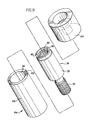
- Figure 8 discloses pivot post 74 which is mounted in the aligned openings 46 and 88.
- the pivot post 74 has a threaded end portion 76 which is secured within the opening 46.
- Cylindrical body portion 78 extends upwardly therefrom and terminates in keyways 80.
- Threaded opening 82 is centrally disposed within body portion 78. The keyways 80 are used for tightening the threaded portion 76 within the support 36.
- FIGS 7 and 9 disclose the pivot mechanism of the invention which utilizes the pivot post of Figure 8.
- Pivot post 74 as best shown in Figure 7, is secured within support 36 and extends upwardly therefrom.
- Eccentric cylider 84 is mounted about body portion 78 of pivot post 74 and is disposed within apertures 86 and 88.
- Washer clamp 94 is mounted within enlarged diameter opening 96 which is coaxial with the openings 86 and 88.
- Bolt 98 extends through washer clamp 94 into central opening 82 and thereby prevents unintended rotation of the eccentric cylinder 84.
- Eccentric cylinder 84 has keyways 100 at the upper end thereof.
- the keyways 100 just as the keyways 80, permit the respective member to be rotated upon the appropriate tool being inserted therein. In this way, the pivot post 74 may be firmly secured to the support 36, or the eccentric cylinder 84 may be rotated.
- Eccentric cylinder 84 has a pair of non-coaxial axes because the axis of the opening 92 is non-coaxial or offset with respect to the axis of the outer wall 102. Consequently, rotation of the eccentric cylinder 84 causes the outer wall 102 to move relative to the axis of rotation of the opening 92. Movement of the outer wall 102 relative to the axis of rotation of the eccentric cylinder 84, as defined by the axis of the opening 92, causes the outer wall 102 to engage the inner walls defined by the openings 86 and 88 and to thereby displace the plate 38 and tailstock 22. Consequently, it is possible to adjust the alignment of the work engaging portion 24 of the tailstock 22 by suitable rotation of the eccentric cylinder 84. It should be noted that the tailstock 22 and plate 38 move substantially linearly with respect to support 36 and the axis of collet 10, rather than being pivoted.
- the washer clamp 94 and its bolt 98 prevent access to pivot post 74 and the eccentric cylinder 84. Should adjustment of the work engaging portion 24 be required, then it is necessary to loosen the bolts 62 and 64, as well as to remove the washer clamp 94 and its bolt 98. The work engaging portion 24 may then be adjusted relative to the axis of collet 10 by rotation of the eccentric cylinder 84 until proper alignment is achieved. Once properly aligned, then the bolt 62 and 64 should then again be properly torqued and the washer clamp 94 and the bolt 98 replaced.
- Figure 6 discloses cylinder 104 and piston 106 used to drive the tailstock 22 toward and away from the spindle assembly S.
- the piston 106 is secured to member 108, such as by bolt 110.
- the member 108 is operably connected with tailstock 22 so that extension and retraction of piston 106 causes corresponding movement of the tailstock 22, as well as telescoping operation of the way cover assemblies 30 and 32.
- base B has an opening 112 at one end thereof which is sized to permit the member 108 to pass therethrough.
- Ledge 114 receives the recessed portion 116 of member 108 and thereby provides a positive forward stop for assuring that the tailstock 22 is in a known position.
- Rear portion 118 of member 108 is engageable with shoulder 120 in order to provide a positive rear stop for like reasons.
- the stops provided by ledge 114 and shoulder 120 permit the machine M to use an hydraulic cylinder 104 for causing reciprocation of the tailstock 22 in a manner which avoids the previous complex servomechanisms and the like.
- the shoulder 120 assures that the tailstock 22 is in a known position when the piston 106 is fully retracted.
- Figure 10 discloses a secondary spindle assembly 122 mounted to support 36 and plate 38 through base 123.
- the secondary spindle assembly 122 includes a rotary spindle mechanism 124 comprising a collet or similar work holding element which thereby permits the workpiece to be exchanged between the collet 10 and the spindle 24. In this way, it is possible to permit the tools 20 to operate on both end portions of a particular piece of work.
- secondary spindle assembly 122 includes the necessary drive motor and operating mechanisms needed to assure operation of the mechanism 124.
- the secondary spindle assembly 122 is normally utilized with the piston 106 in the fully retracted position. Therefore, the machine controls (not shown) are always sure of the location of the workpiece (not shown). It is merely necessary to move the turret assembly T relative to the secondary spindle assembly 122 in order to complete the part.
- the tailstock 22 and the turret assembly T move very rapidly with respect to each other and with respect to the base B.
- the machine tool M is, customarily, either manually operated or operated by means of a programmed control system. Should an error in the programming or manual operation occur, then it is possible for the turret assembly T to engage the tailstock 22 with substantial force.
- the bolts 62 and 64 which secure the plate 38 and the tailstock 22 in contiguous overlying relation to support 36, move in the slots 42, 43 and 44, 45 and thereby permit the plate 38 and the tailstock 22, or the secondary spindle 122, to move relative to the support 36. Movement of the plate 38 and the tailstock 22 relative to the support 36 prevents the ways 26 and 28 from being damaged, and thereby the machine M be rendered unserviceable.
- the slots 42, 43 and 44, 45 are angularly disposed relative to the edge 48 and thereby permit the plate 38 and the tailstock 22 or the secondary spindle 122 to pivot about pivot post 74.
- the pivoting action occurs within a defined range of amplitude by reason of the proximity switch 54 and the force absorbed by bolts 62 and 64 prior to and when being moved in the slots.
- the controls (not shown) of the machine tool M are notified and all further action is stopped.
- This emergency stop feature prevents further damage to the machine M and assures that the ways 26 and 28 are not damaged.
- the heads 66 and 68 and washers 67 by being free to slide within the recessed portion 70 and 72, are likewise not damaged.
- slots 42, 43 and 44, 45 are sufficiently long to permit the impact force to be absorbed without the bolts 62 and 64 striking an end portion thereof and becoming bent or broken.
- pivot post 74 in order to permit the plate 38 and tailstock 22 to pivot, it should be clear that the post 74 could be replaced with a further bolt and slot combination. In that event, the plate 38 and tailstock 22 would move linearly, or in any desired direction, but there would be no adjustment feature.
- the adjustment feature is important, in our opinion, in order to accommodate wear, and to permit a tailstock to be replaced with another tailstock from inventory.
Landscapes
- Engineering & Computer Science (AREA)
- Mechanical Engineering (AREA)
- Auxiliary Devices For Machine Tools (AREA)
- Portable Nailing Machines And Staplers (AREA)
- Turning (AREA)
- Bending Of Plates, Rods, And Pipes (AREA)
- Connection Of Plates (AREA)
Abstract

Description
- A conventional machine tool has a base to which is secured a spindle which rotates the workpiece. The machine may have a tailstock to maintain the workpiece in proper alignment as the workpiece is operated upon by a tool. The tool is typically mounted to a turret which is movable relative to the spindle through a cross-slide. The turret may move parallel to the axis of the workpiece and/or transverse thereto. Proper operation of the machine tool requires that the various elements cooperate in a manner which assures good part repeatability.
- The tailstock and turret are, as noted, movable both toward and away from the spindle. Additionally, the turret is movable toward the tailstock, thereby presenting the possibility of contacting the tailstock should the machine be improperly programmed or should a malfunction occur. The ever increasing speed with which the tailstock and cross-slide move have necessitated the use of accurately aligned track systems upon which to move. For example, linear ways have now become conventional because they permit the tailstock and turret to move with speeds in excess of several hundred inches per minute.
- The use of linear ways, however, requires that they be accurately initially aligned, and maintained in alignment. Should the ways get out of alignment or otherwise become distorted, then the relevant tool element will not properly move therealong. One cause of misalignment or damage to the ways is through impact of the turret with the tailstock, or other tool element used in place of the tailstock.
- Should the linear ways become damaged, such as by a collision between the turret and the tailstock, then it has previously been necessary for those ways to be replaced for the machine to once again be capable of functioning with the tolerances required. Removal and replacement of the linear ways is a time consuming process, normally requiring in excess of one day. During that period, the machine tool is not operating and thereby represents a loss of productive assets.
- In view of the above, it can be seen that there is a need for a tool element mounting system which alleviates the time consuming process of way replacement in the event of a collision between the turret and the tailstock. The disclosed invention is a method of mounting a tool element in order to prevent damage to the linear ways by permitting the tailstock or other such tool element to move relative to those ways, and to be replaced rapidly and in accurate alignment.
- The primary object of the disclosed invention is a break away machine tool assembly and method of mounting which prevents damage to the machine tool ways and which permits the tailstock or other similar tool element to be rapidly repositioned and accurately aligned in order to avoid excessive down time while assuring good part repeatability.
- A break away machine tool assembly according to the invention comprises a support. A bearing plate overlies the support and is contiguous thereto and is movable relative thereto. A tool element overlies and is contiguous the plate and is movable therewith. Means releasably secure the plate and the element in overlying relation to the support for permitting the plate and the element to move relative to the support within a defined range upon being subjected to an impact.
- A machine tool assembly comprises a base to which a headstock is mounted at one end thereof and the headstock includes means rotatable on a first axis for gripping and releasing work. A first tool element is displaceably mounted to the base and includes a work engaging portion coaxial with the first axis and the first tool element is movable on a second axis parallel to the first axis. A second tool element is displaceably mounted to the base and includes a work engaging portion. The second tool element is movable on a third axis parallel to the first axis and also on a fourth axis generally transverse to the first axis. The first tool element includes a support, a bearing plate overlying and contiguous the support, tool means overlying and contiguous the plate, and means releaseably secure the plate and the tool means in overlying relation to the support for permitting the plate and the tool means to move relative to the support within a defined range upon the first and second tool elements contacting each other.
- The method of mounting a machine tool tool element to prevent damage to the ways comprises the steps of providing a support movable along the machine tool base. Overlying the support is a bearing plate which is also contiguous therewith. Overlying the bearing plate and contiguous therewith is a tool element. Securing the bearing plate and tool element to the support is accomplished through releaseable securing means which permit the bearing plate and the tool element to move relative to the support within a defined range upon the plate and the tool element being subjected to impact.
- These and other objects and advantages of the invention will be readily apparent in view of the following description and drawings of the above described invention.
- The above and other objects and advantages and novel features of the present invention will become apparent from the following detailed description of the preferred embodiment of the invention illustrated in the accompanying drawings, wherein:
- Figure 1 is a plan view of a machine tool according to the invention with arrows indicating direction of movement;
- Figure 2 is a cross-sectional view taken along the section 2-2 of Figure 1 and with portions broken away for clarity;
- Figure 3 is an elevational view, with portions broken away, of the tailstock of Figure 1;
- Figure 4 is a cross-sectional view taken along the section 4-4 of Figure 3 and viewed in the direction of the arrows and with arrows and dotted lines indicating movement;
- Figure 5 is a plan view of the tailstock of Figure 1;
- Figure 6 is a fragmentary cross-sectional view taken along the section 6-6 of Figure 1;
- Figure 7 is a fragmentary cross-sectional view of the pivot mechanism used with the invention, the section being taken along the lines 7-7 of Figure 5 and viewed in the direction of the arrows;
- Figure 8 is an elevational view; partially in section, of the pivot post of the invention;
- Figure 9 is an exploded assembly drawing of the pivoting and adjustment mechanism of the invention;
- Figure 10 is an elevational view of a secondary spindle used in place of the tailstock of Figure 5; and,
- Figure 11 is a fragmentary cross-sectional view taken along the section 11-11 of Figure 4.
- Machine tool M, as best shown in Figure 1, includes a base B to one end of which headstock H is mounted. Headstock H include a spindle assembly S with a rotary work holder, such as
collet 10. The base B may, in certain instances, be disposed at a substantial angle to the horizontal in order to permit cuttings and the like to slide along the base B in order to facilitate removal. - Turret assembly T is movably mounted on cross-slide C. The cross-slide C include telescoping means 12 permitting the turret assembly T to move generally transverse to the axis of
collet 10 and furthermore includes telescoping means 14 permitting movement parallel to the axis ofcollet 10. The turret assembly T has amotor 16 to which indexabletool holding head 18 is mounted. Thehead 18 carries a number oftools 20 in order to permit a piece of work rotated by thecollet 10 to be operated on, and to thereby achieve a desired shape, configuration or the like. The motion of the turret assembly T parallel and transverse to the axis of thecollet 10 permits thetools 20 to be moved longitudinally and transversely of the workpiece. - Tailstock 22 is similarly mounted to base B for reciprocation toward and away from
collet 10. Thetailstock 22 has awork engaging portion 24 which is coaxial with the axis of rotation ofcollet 10. Thetailstock 22 is movable upon spacedparallel ways ways tailstock 22 toward and away from thecollet 10. Theways way cover systems 30 and 32 are operably connected to and movable withtailstock 22 and extend therefrom for overlying and protectingways ways way cover systems 30 and 32 comprises a plurality of U-shapedcovers 34 which are nestled one in another in order to achieve a telescopic action as thetailstock 22 moves. -
Support 36, as best shown in Figure 2, is secured toway cover systems 30 and 32.Bearing plate 38 overlies and is contiguous withsupport 36. The bearingplate 38 is, preferably, comprised of stainless steel and a non-water soluble lubricant is disposed between theplate 38 and thesupport 36 in order to prevent galling and to permit movement of theplate 38 relative to thesupport 36. Thetailstock 22 has abase portion 40 which overlies and is contiguous withplate 38. Preferably, a non-water soluble lubricant is disposed between thebase portion 40 and theplate 38 for like reasons. - The
plate 38 has a pair ofoval slots slots 43 and 45 in thesupport 36, respectively, as best shown in Figure 11. Theslots slots 43 and 45 when thetailstock 22 is in the operating configuration of Figure 1. Thesupport 36 and theplate 38 also have alignedopenings slots forward edge 48. Each of theslots edge 48 in order to facilitate pivoting of theplate 38 around theopenings slots edge 48 than are theslots 42 and 43 because theslots openings slots 42 and 43. - Figures 3 and 4
disclose recess 50 insupport 36 along lower edge 52 thereof. The edge 52 is, in the normal operating position of Figure 1, parallel to the axis of rotation of thecollet 10, while theedge 48 extends generally transverse thereto.Proximity switch 54 is mounted inrecess 50 and is disposed belowplate 38. Theplate 38 has a cut-outportion 56 which corresponds to the configuration of therecess 50. In this way, movement of theplate 38 about the axis of pivoting defined by theopenings proximity switch 54. When theproximity switch 54 senses movement of theplate 38, then a signal to that effect is sent bycable 58 to the automatic controls (not shown) of the machine M. Figure 3 also disclosescover plate 60 which is secured tobase portion 40 and protects theproximity switch 54. -
Bolts 62 and 64 are secured intailstock 22 and extend therefrom through the alignedslots bolts 62 and 64 has a threaded portion, only the threadedportion 65 ofbolt 64 being shown in Figure 3, and a head portion and thehead portions support 36, as best shown in Figure 2.Washers 67 are disposed betweenhead portions support 36. Thesupport 36 has recessedportions head portions washers 67, as best shown in Figure 2. Thebolts 62 and 64 are, preferably, torqued to 40 ft/lbs., in order to secure theplate 38 and thetailstock 22 to thesupport 36, and to permit theplate 38 andtailstock 22 to move relative thereto when subjected to impact. Thewashers 67 minimize localization of the compression force because their area exceeds that ofhead portions - Figure 8 discloses
pivot post 74 which is mounted in the alignedopenings pivot post 74 has a threadedend portion 76 which is secured within theopening 46.Cylindrical body portion 78 extends upwardly therefrom and terminates inkeyways 80. Threadedopening 82 is centrally disposed withinbody portion 78. Thekeyways 80 are used for tightening the threadedportion 76 within thesupport 36. - Figures 7 and 9 disclose the pivot mechanism of the invention which utilizes the pivot post of Figure 8. Pivot
post 74, as best shown in Figure 7, is secured withinsupport 36 and extends upwardly therefrom.Eccentric cylider 84 is mounted aboutbody portion 78 ofpivot post 74 and is disposed withinapertures Washer clamp 94 is mounted withinenlarged diameter opening 96 which is coaxial with theopenings Bolt 98 extends throughwasher clamp 94 intocentral opening 82 and thereby prevents unintended rotation of theeccentric cylinder 84. -
Eccentric cylinder 84, as best shown in Figure 9, haskeyways 100 at the upper end thereof. Thekeyways 100, just as thekeyways 80, permit the respective member to be rotated upon the appropriate tool being inserted therein. In this way, thepivot post 74 may be firmly secured to thesupport 36, or theeccentric cylinder 84 may be rotated. -
Eccentric cylinder 84, as suggested by its name, has a pair of non-coaxial axes because the axis of theopening 92 is non-coaxial or offset with respect to the axis of theouter wall 102. Consequently, rotation of theeccentric cylinder 84 causes theouter wall 102 to move relative to the axis of rotation of theopening 92. Movement of theouter wall 102 relative to the axis of rotation of theeccentric cylinder 84, as defined by the axis of theopening 92, causes theouter wall 102 to engage the inner walls defined by theopenings plate 38 andtailstock 22. Consequently, it is possible to adjust the alignment of thework engaging portion 24 of thetailstock 22 by suitable rotation of theeccentric cylinder 84. It should be noted that thetailstock 22 andplate 38 move substantially linearly with respect to support 36 and the axis ofcollet 10, rather than being pivoted. - As noted, the
washer clamp 94 and itsbolt 98 prevent access to pivotpost 74 and theeccentric cylinder 84. Should adjustment of thework engaging portion 24 be required, then it is necessary to loosen thebolts 62 and 64, as well as to remove thewasher clamp 94 and itsbolt 98. Thework engaging portion 24 may then be adjusted relative to the axis ofcollet 10 by rotation of theeccentric cylinder 84 until proper alignment is achieved. Once properly aligned, then thebolt 62 and 64 should then again be properly torqued and thewasher clamp 94 and thebolt 98 replaced. - Figure 6 discloses
cylinder 104 andpiston 106 used to drive thetailstock 22 toward and away from the spindle assembly S. Thepiston 106 is secured tomember 108, such as bybolt 110. Themember 108 is operably connected withtailstock 22 so that extension and retraction ofpiston 106 causes corresponding movement of thetailstock 22, as well as telescoping operation of theway cover assemblies 30 and 32. It can be noted in Figure 6 that base B has anopening 112 at one end thereof which is sized to permit themember 108 to pass therethrough.Ledge 114 receives the recessedportion 116 ofmember 108 and thereby provides a positive forward stop for assuring that thetailstock 22 is in a known position.Rear portion 118 ofmember 108 is engageable withshoulder 120 in order to provide a positive rear stop for like reasons. - The stops provided by
ledge 114 andshoulder 120 permit the machine M to use anhydraulic cylinder 104 for causing reciprocation of thetailstock 22 in a manner which avoids the previous complex servomechanisms and the like. Theshoulder 120 assures that thetailstock 22 is in a known position when thepiston 106 is fully retracted. - Figure 10 discloses a
secondary spindle assembly 122 mounted to support 36 andplate 38 throughbase 123. Thesecondary spindle assembly 122 includes arotary spindle mechanism 124 comprising a collet or similar work holding element which thereby permits the workpiece to be exchanged between thecollet 10 and thespindle 24. In this way, it is possible to permit thetools 20 to operate on both end portions of a particular piece of work. Naturally,secondary spindle assembly 122 includes the necessary drive motor and operating mechanisms needed to assure operation of themechanism 124. - The
secondary spindle assembly 122 is normally utilized with thepiston 106 in the fully retracted position. Therefore, the machine controls (not shown) are always sure of the location of the workpiece (not shown). It is merely necessary to move the turret assembly T relative to thesecondary spindle assembly 122 in order to complete the part. - As previously explained, the
tailstock 22 and the turret assembly T move very rapidly with respect to each other and with respect to the base B. The machine tool M is, customarily, either manually operated or operated by means of a programmed control system. Should an error in the programming or manual operation occur, then it is possible for the turret assembly T to engage thetailstock 22 with substantial force. In the event of such an impact, then thebolts 62 and 64 which secure theplate 38 and thetailstock 22 in contiguous overlying relation to support 36, move in theslots plate 38 and thetailstock 22, or thesecondary spindle 122, to move relative to thesupport 36. Movement of theplate 38 and thetailstock 22 relative to thesupport 36 prevents theways - As noted, the
slots edge 48 and thereby permit theplate 38 and thetailstock 22 or thesecondary spindle 122 to pivot aboutpivot post 74. The pivoting action occurs within a defined range of amplitude by reason of theproximity switch 54 and the force absorbed bybolts 62 and 64 prior to and when being moved in the slots. Once theproximity switch 54 senses movement of theplate 38, then the controls (not shown) of the machine tool M are notified and all further action is stopped. This emergency stop feature prevents further damage to the machine M and assures that theways heads washers 67, by being free to slide within the recessedportion secondary spindle 122 should a collision occur. Also,slots bolts 62 and 64 striking an end portion thereof and becoming bent or broken. - Should a collision between the turret assembly T and the
tailstock 22 orsecondary spindle 122 occur, then it is possible to once again have the machine tool M useable within a very short period because theways bolts 62 and 64 and to swing theplate 38 and thetailstock 22 orsecondary spindle 122 into general alignment with the axis of rotation of thecollet 10. Theeccentric cylinder 84 is then rotated in order to achieve proper alignment between thework engaging portion 24 or the axis of rotation of thespindle 124 with the axis of rotation of thecollet 10. Once proper alignment has been achieved, then thebolts 62 and 64 are once again torqued to 40 ft/lbs., or whatever torque is required, and thewasher clamp 94 andbolt 98 replaced. The entire procedure requires just a few minutes, as opposed to the two days or more required with prior systems. - While we prefer the use of pivot post 74 in order to permit the
plate 38 andtailstock 22 to pivot, it should be clear that thepost 74 could be replaced with a further bolt and slot combination. In that event, theplate 38 andtailstock 22 would move linearly, or in any desired direction, but there would be no adjustment feature. The adjustment feature is important, in our opinion, in order to accommodate wear, and to permit a tailstock to be replaced with another tailstock from inventory. - While the invention has been described has having a preferred design, it is understood that it is capable of further modifications, uses, and/or adaptations of the invention, following in general the principle of the invention, and including such departures from the present disclosure as come within known or customary practice in the art to which the invention pertains, and as may be applied to the central features hereinbefore set forth, and fall within the scope of the invention of the limits of the appended claims.
Claims (32)
Applications Claiming Priority (2)
| Application Number | Priority Date | Filing Date | Title |
|---|---|---|---|
| US199090 | 1988-05-26 | ||
| US07/199,090 US4893532A (en) | 1988-05-26 | 1988-05-26 | Break away tool element and method of mounting |
Publications (3)
| Publication Number | Publication Date |
|---|---|
| EP0343315A2 true EP0343315A2 (en) | 1989-11-29 |
| EP0343315A3 EP0343315A3 (en) | 1991-07-10 |
| EP0343315B1 EP0343315B1 (en) | 1994-08-24 |
Family
ID=22736169
Family Applications (1)
| Application Number | Title | Priority Date | Filing Date |
|---|---|---|---|
| EP89100091A Expired - Lifetime EP0343315B1 (en) | 1988-05-26 | 1989-01-04 | Break away tool element and method of mounting |
Country Status (4)
| Country | Link |
|---|---|
| US (1) | US4893532A (en) |
| EP (1) | EP0343315B1 (en) |
| AT (1) | ATE110313T1 (en) |
| DE (1) | DE68917640D1 (en) |
Cited By (2)
| Publication number | Priority date | Publication date | Assignee | Title |
|---|---|---|---|---|
| EP1004395A3 (en) * | 1998-11-27 | 2002-06-19 | Machining Centers Manufacturing S.p.A. | Shock-absorbing device for spindle headstocks |
| EP1182003A3 (en) * | 2000-08-16 | 2002-06-19 | Index-Werke Gmbh & Co. Kg Hahn & Tessky | Machine tool and method of operating a machine tool |
Families Citing this family (9)
| Publication number | Priority date | Publication date | Assignee | Title |
|---|---|---|---|---|
| US4995434A (en) * | 1989-08-08 | 1991-02-26 | Christiansen Clead M | Woodworking lathe tailstock assembly |
| FR2667935B1 (en) * | 1990-10-12 | 1997-01-17 | Valeo Thermique Moteur Sa | DEVICE FOR FIXING A SECONDARY HEAT EXCHANGER OF THE COIL TYPE ON A MAIN HEAT EXCHANGER AND SET OF EXCHANGERS THUS OBTAINED |
| DE4229423C3 (en) * | 1992-09-03 | 1998-10-01 | Index Werke Kg Hahn & Tessky | Lathe |
| US5251522A (en) * | 1992-11-02 | 1993-10-12 | Chin Long Wu | Protective apparatus preventing lathe tool from breaking |
| US5565116A (en) * | 1995-01-18 | 1996-10-15 | David D. Barton | Stud welding |
| DE19516984C2 (en) * | 1995-05-09 | 1998-04-30 | Sauter Kg Feinmechanik | Tool turret |
| US20070256811A1 (en) * | 2006-05-04 | 2007-11-08 | Jerome Matter | Mounting boss for a brazed heat exchanger |
| JP4981556B2 (en) * | 2007-07-12 | 2012-07-25 | 津田駒工業株式会社 | Machine tool spindle head |
| US20110271804A1 (en) * | 2010-05-04 | 2011-11-10 | Chun-Ta Hsieh | Centre drilling/turning tool holder |
Family Cites Families (16)
| Publication number | Priority date | Publication date | Assignee | Title |
|---|---|---|---|---|
| US1772940A (en) * | 1929-06-08 | 1930-08-12 | Emil G Forsberg | Lathe-driven tailstock feed |
| US2243588A (en) * | 1939-07-31 | 1941-05-27 | Wahnish George | Lathe tailstock adjusting means |
| US2357062A (en) * | 1943-10-20 | 1944-08-29 | Henry C Stoll | Angle plate for lathes |
| US2451658A (en) * | 1943-12-03 | 1948-10-19 | Bugtember Ettore | Mounting of grinding wheels, especially on grinding machines |
| US2470871A (en) * | 1945-11-03 | 1949-05-24 | Gilbert C Schwantes | Headstock attachment for lathes |
| FR1012035A (en) * | 1949-05-20 | 1952-07-02 | Cazeneuve Sa | Improvements made to the safety devices of machine tool counterpoints |
| US2802385A (en) * | 1953-11-04 | 1957-08-13 | Walter V Schmidt | Tailstock clamp unit |
| US3600988A (en) * | 1969-07-07 | 1971-08-24 | Lear Siegler Inc | Multiple adjustable stock |
| GB1603791A (en) * | 1978-05-24 | 1981-11-25 | White Bsa Tools Ltd | Overload system for a machine tool |
| US4442725A (en) * | 1981-05-26 | 1984-04-17 | Shigiya Machinery Works, Ltd. | Shock absorbing apparatus for travelling a table or tool rest in machine tools |
| DE3137878C2 (en) * | 1981-09-23 | 1990-04-19 | Oerlikon-Boehringer GmbH, 7320 Göppingen | Overload protection for the feed drive on a machine tool |
| US4506569A (en) * | 1982-11-02 | 1985-03-26 | Hardinge Brothers, Inc. | Multiple axis slant bed machine |
| SU1140930A1 (en) * | 1984-01-06 | 1985-02-23 | Курское Отделение Всесоюзного Научно-Исследовательского,Проектно-Конструкторского И Технологического Института Низковольтного Аппаратостроения | Device for setting metal-cutting machine working member in working position |
| US4661038A (en) * | 1984-10-09 | 1987-04-28 | Siemens Aktiengesellschaft | Protection arrangement for industrial robotics |
| EP0228007B1 (en) * | 1985-12-28 | 1992-04-15 | Paul Forkardt GmbH & Co. KG | Machine tool and its method of operation |
| US4800790A (en) * | 1986-11-14 | 1989-01-31 | Cincinnati Milacron Inc. | Modal coupling tailstock |
-
1988
- 1988-05-26 US US07/199,090 patent/US4893532A/en not_active Expired - Lifetime
-
1989
- 1989-01-04 DE DE68917640T patent/DE68917640D1/en not_active Expired - Lifetime
- 1989-01-04 AT AT89100091T patent/ATE110313T1/en not_active IP Right Cessation
- 1989-01-04 EP EP89100091A patent/EP0343315B1/en not_active Expired - Lifetime
Cited By (2)
| Publication number | Priority date | Publication date | Assignee | Title |
|---|---|---|---|---|
| EP1004395A3 (en) * | 1998-11-27 | 2002-06-19 | Machining Centers Manufacturing S.p.A. | Shock-absorbing device for spindle headstocks |
| EP1182003A3 (en) * | 2000-08-16 | 2002-06-19 | Index-Werke Gmbh & Co. Kg Hahn & Tessky | Machine tool and method of operating a machine tool |
Also Published As
| Publication number | Publication date |
|---|---|
| EP0343315B1 (en) | 1994-08-24 |
| DE68917640D1 (en) | 1994-09-29 |
| ATE110313T1 (en) | 1994-09-15 |
| EP0343315A3 (en) | 1991-07-10 |
| US4893532A (en) | 1990-01-16 |
Similar Documents
| Publication | Publication Date | Title |
|---|---|---|
| US5769577A (en) | Removable spinning tool assembly | |
| US4893532A (en) | Break away tool element and method of mounting | |
| US4196506A (en) | Tool changer machining center | |
| US5367754A (en) | Gang tooling for a computerized numerically controlled lathe | |
| GB2323318A (en) | Adjustable punch assembly | |
| DE2412533A1 (en) | TOOL CHANGING DEVICE | |
| US4053968A (en) | Tool support for tool interchange system | |
| US4338709A (en) | Magazine for storing toolholders with tools mounted therein for machine tools | |
| EP2329913B1 (en) | Vertical processing centre in gantry form with a balancing device for the workpiece table | |
| EP0433895A1 (en) | Method of detecting the presence or the dimensions or the correct position of a workpiece on a machine tool | |
| EP0296460A1 (en) | Tool for circumferential machining of workpieces, particularly for boring | |
| US4884481A (en) | Radially adjustable tool | |
| DE1602774C3 (en) | Device for optionally attaching a chuck to the spindle of a machine tool or to a chuck change disk and chuck for this purpose | |
| EP0128512B1 (en) | Tool holder for machine tools | |
| US5772566A (en) | Machine tool | |
| DE19825922C2 (en) | Lens wheel grinding machine | |
| DE3822565C2 (en) | ||
| US4250777A (en) | Boring head | |
| JPS61288951A (en) | Milling machine or drilling machine | |
| CN113997109B (en) | Cutter head of machine tool | |
| JPS5856707A (en) | Regulator for rotatory tool | |
| EP2319646B1 (en) | Whirling cutting device | |
| US6626058B2 (en) | C-axis driving system for machine tools | |
| CA1279467C (en) | Transfer press | |
| DE3002060A1 (en) | Angled drill attachment for machine tool - has spring loaded bolt and locating key to suit spindle housing |
Legal Events
| Date | Code | Title | Description |
|---|---|---|---|
| PUAI | Public reference made under article 153(3) epc to a published international application that has entered the european phase |
Free format text: ORIGINAL CODE: 0009012 |
|
| AK | Designated contracting states |
Kind code of ref document: A2 Designated state(s): AT BE CH DE ES FR GB GR IT LI LU NL SE |
|
| PUAL | Search report despatched |
Free format text: ORIGINAL CODE: 0009013 |
|
| AK | Designated contracting states |
Kind code of ref document: A3 Designated state(s): AT BE CH DE ES FR GB GR IT LI LU NL SE |
|
| 17P | Request for examination filed |
Effective date: 19911231 |
|
| 17Q | First examination report despatched |
Effective date: 19930517 |
|
| GRAA | (expected) grant |
Free format text: ORIGINAL CODE: 0009210 |
|
| AK | Designated contracting states |
Kind code of ref document: B1 Designated state(s): AT BE CH DE ES FR GB GR IT LI LU NL SE |
|
| PG25 | Lapsed in a contracting state [announced via postgrant information from national office to epo] |
Ref country code: IT Free format text: LAPSE BECAUSE OF FAILURE TO SUBMIT A TRANSLATION OF THE DESCRIPTION OR TO PAY THE FEE WITHIN THE PRESCRIBED TIME-LIMIT;WARNING: LAPSES OF ITALIAN PATENTS WITH EFFECTIVE DATE BEFORE 2007 MAY HAVE OCCURRED AT ANY TIME BEFORE 2007. THE CORRECT EFFECTIVE DATE MAY BE DIFFERENT FROM THE ONE RECORDED. Effective date: 19940824 Ref country code: GR Free format text: LAPSE BECAUSE OF FAILURE TO SUBMIT A TRANSLATION OF THE DESCRIPTION OR TO PAY THE FEE WITHIN THE PRESCRIBED TIME-LIMIT Effective date: 19940824 Ref country code: FR Effective date: 19940824 Ref country code: LI Effective date: 19940824 Ref country code: BE Effective date: 19940824 Ref country code: CH Effective date: 19940824 Ref country code: AT Effective date: 19940824 Ref country code: ES Free format text: THE PATENT HAS BEEN ANNULLED BY A DECISION OF A NATIONAL AUTHORITY Effective date: 19940824 Ref country code: NL Effective date: 19940824 |
|
| REF | Corresponds to: |
Ref document number: 110313 Country of ref document: AT Date of ref document: 19940915 Kind code of ref document: T |
|
| REF | Corresponds to: |
Ref document number: 68917640 Country of ref document: DE Date of ref document: 19940929 |
|
| PG25 | Lapsed in a contracting state [announced via postgrant information from national office to epo] |
Ref country code: SE Effective date: 19941124 |
|
| PG25 | Lapsed in a contracting state [announced via postgrant information from national office to epo] |
Ref country code: DE Effective date: 19941125 |
|
| REG | Reference to a national code |
Ref country code: CH Ref legal event code: PL |
|
| EN | Fr: translation not filed | ||
| PG25 | Lapsed in a contracting state [announced via postgrant information from national office to epo] |
Ref country code: LU Free format text: LAPSE BECAUSE OF NON-PAYMENT OF DUE FEES Effective date: 19950131 |
|
| NLV1 | Nl: lapsed or annulled due to failure to fulfill the requirements of art. 29p and 29m of the patents act | ||
| PLBE | No opposition filed within time limit |
Free format text: ORIGINAL CODE: 0009261 |
|
| STAA | Information on the status of an ep patent application or granted ep patent |
Free format text: STATUS: NO OPPOSITION FILED WITHIN TIME LIMIT |
|
| 26N | No opposition filed | ||
| PGFP | Annual fee paid to national office [announced via postgrant information from national office to epo] |
Ref country code: GB Payment date: 20001227 Year of fee payment: 13 |
|
| REG | Reference to a national code |
Ref country code: GB Ref legal event code: IF02 |
|
| PG25 | Lapsed in a contracting state [announced via postgrant information from national office to epo] |
Ref country code: GB Free format text: LAPSE BECAUSE OF NON-PAYMENT OF DUE FEES Effective date: 20020104 |
|
| GBPC | Gb: european patent ceased through non-payment of renewal fee |
Effective date: 20020104 |