EP0343267A1 - Methode und Gerät zur Regelung der Ultrafiltration während einer Hemodialyse - Google Patents
Methode und Gerät zur Regelung der Ultrafiltration während einer Hemodialyse Download PDFInfo
- Publication number
- EP0343267A1 EP0343267A1 EP19880108276 EP88108276A EP0343267A1 EP 0343267 A1 EP0343267 A1 EP 0343267A1 EP 19880108276 EP19880108276 EP 19880108276 EP 88108276 A EP88108276 A EP 88108276A EP 0343267 A1 EP0343267 A1 EP 0343267A1
- Authority
- EP
- European Patent Office
- Prior art keywords
- dialysate
- receptacle
- fresh
- receptacles
- hemodialyzer
- Prior art date
- Legal status (The legal status is an assumption and is not a legal conclusion. Google has not performed a legal analysis and makes no representation as to the accuracy of the status listed.)
- Withdrawn
Links
Images

Classifications
-
- A—HUMAN NECESSITIES
- A61—MEDICAL OR VETERINARY SCIENCE; HYGIENE
- A61M—DEVICES FOR INTRODUCING MEDIA INTO, OR ONTO, THE BODY; DEVICES FOR TRANSDUCING BODY MEDIA OR FOR TAKING MEDIA FROM THE BODY; DEVICES FOR PRODUCING OR ENDING SLEEP OR STUPOR
- A61M1/00—Suction or pumping devices for medical purposes; Devices for carrying-off, for treatment of, or for carrying-over, body-liquids; Drainage systems
- A61M1/14—Dialysis systems; Artificial kidneys; Blood oxygenators ; Reciprocating systems for treatment of body fluids, e.g. single needle systems for hemofiltration or pheresis
- A61M1/16—Dialysis systems; Artificial kidneys; Blood oxygenators ; Reciprocating systems for treatment of body fluids, e.g. single needle systems for hemofiltration or pheresis with membranes
- A61M1/1601—Control or regulation
- A61M1/1603—Regulation parameters
- A61M1/1605—Physical characteristics of the dialysate fluid
-
- A—HUMAN NECESSITIES
- A61—MEDICAL OR VETERINARY SCIENCE; HYGIENE
- A61M—DEVICES FOR INTRODUCING MEDIA INTO, OR ONTO, THE BODY; DEVICES FOR TRANSDUCING BODY MEDIA OR FOR TAKING MEDIA FROM THE BODY; DEVICES FOR PRODUCING OR ENDING SLEEP OR STUPOR
- A61M1/00—Suction or pumping devices for medical purposes; Devices for carrying-off, for treatment of, or for carrying-over, body-liquids; Drainage systems
- A61M1/14—Dialysis systems; Artificial kidneys; Blood oxygenators ; Reciprocating systems for treatment of body fluids, e.g. single needle systems for hemofiltration or pheresis
- A61M1/16—Dialysis systems; Artificial kidneys; Blood oxygenators ; Reciprocating systems for treatment of body fluids, e.g. single needle systems for hemofiltration or pheresis with membranes
- A61M1/1621—Constructional aspects thereof
- A61M1/1635—Constructional aspects thereof with volume chamber balancing devices between used and fresh dialysis fluid
- A61M1/1641—Constructional aspects thereof with volume chamber balancing devices between used and fresh dialysis fluid linked by pistons
-
- A—HUMAN NECESSITIES
- A61—MEDICAL OR VETERINARY SCIENCE; HYGIENE
- A61M—DEVICES FOR INTRODUCING MEDIA INTO, OR ONTO, THE BODY; DEVICES FOR TRANSDUCING BODY MEDIA OR FOR TAKING MEDIA FROM THE BODY; DEVICES FOR PRODUCING OR ENDING SLEEP OR STUPOR
- A61M1/00—Suction or pumping devices for medical purposes; Devices for carrying-off, for treatment of, or for carrying-over, body-liquids; Drainage systems
- A61M1/34—Filtering material out of the blood by passing it through a membrane, i.e. hemofiltration or diafiltration
- A61M1/3403—Regulation parameters
- A61M1/341—Regulation parameters by measuring the filtrate rate or volume
-
- A—HUMAN NECESSITIES
- A61—MEDICAL OR VETERINARY SCIENCE; HYGIENE
- A61M—DEVICES FOR INTRODUCING MEDIA INTO, OR ONTO, THE BODY; DEVICES FOR TRANSDUCING BODY MEDIA OR FOR TAKING MEDIA FROM THE BODY; DEVICES FOR PRODUCING OR ENDING SLEEP OR STUPOR
- A61M1/00—Suction or pumping devices for medical purposes; Devices for carrying-off, for treatment of, or for carrying-over, body-liquids; Drainage systems
- A61M1/34—Filtering material out of the blood by passing it through a membrane, i.e. hemofiltration or diafiltration
- A61M1/342—Adding solutions to the blood, e.g. substitution solutions
- A61M1/3424—Substitution fluid path
- A61M1/3427—Substitution fluid path back through the membrane, e.g. by inverted trans-membrane pressure [TMP]
-
- A—HUMAN NECESSITIES
- A61—MEDICAL OR VETERINARY SCIENCE; HYGIENE
- A61M—DEVICES FOR INTRODUCING MEDIA INTO, OR ONTO, THE BODY; DEVICES FOR TRANSDUCING BODY MEDIA OR FOR TAKING MEDIA FROM THE BODY; DEVICES FOR PRODUCING OR ENDING SLEEP OR STUPOR
- A61M2205/00—General characteristics of the apparatus
- A61M2205/33—Controlling, regulating or measuring
- A61M2205/3331—Pressure; Flow
- A61M2205/3334—Measuring or controlling the flow rate
-
- A—HUMAN NECESSITIES
- A61—MEDICAL OR VETERINARY SCIENCE; HYGIENE
- A61M—DEVICES FOR INTRODUCING MEDIA INTO, OR ONTO, THE BODY; DEVICES FOR TRANSDUCING BODY MEDIA OR FOR TAKING MEDIA FROM THE BODY; DEVICES FOR PRODUCING OR ENDING SLEEP OR STUPOR
- A61M2205/00—General characteristics of the apparatus
- A61M2205/33—Controlling, regulating or measuring
- A61M2205/3379—Masses, volumes, levels of fluids in reservoirs, flow rates
- A61M2205/3389—Continuous level detection
-
- A—HUMAN NECESSITIES
- A61—MEDICAL OR VETERINARY SCIENCE; HYGIENE
- A61M—DEVICES FOR INTRODUCING MEDIA INTO, OR ONTO, THE BODY; DEVICES FOR TRANSDUCING BODY MEDIA OR FOR TAKING MEDIA FROM THE BODY; DEVICES FOR PRODUCING OR ENDING SLEEP OR STUPOR
- A61M2205/00—General characteristics of the apparatus
- A61M2205/50—General characteristics of the apparatus with microprocessors or computers
Definitions
- the present invention relates to volumetric ultrafiltration or infusion systems. More particularly, the invention concerns a method and apparatus for controlling ultrafiltration during hemodialysis.
- Ultrafiltration is a procedure during hemodialysis wherein excess water is removed from the blood. It is well-known that satisfactory ultrafiltration is achieved by maintaining dialysate pressure within a dialyzer lower than that of the blood pressure. While excess water in the blood is being removed, the rate of ultrafiltration is a critical factor, since rapid removal of water from the blood may traumatically affect the patient.
- Various solutions for controlling the rate of ultrafiltration have been proposed, such as those described in U.S. Patent Nos. 3,939,069; 4,209,391; and 4,267,041.
- U.S. Patent No. 4,209,391 achieves ultrafiltration control by means of a volumetric system that relies upon volume conservation.
- a known and equal quantity of fluid is moved into and out of the dialyzer by two matched positive displacement pumps.
- a third pump extracts the programmed amount of dialysate from the fresh dialysate supply.
- the spent dialysate pump demands a fixed quantity of fluid and the difference that is extracted from the fresh dialysate supply is made up by the ultrafiltrate drawn across the dialyzer membrane.
- U.S. Patent No. 4,267,041 discloses an apparatus including a plurality of storage containers for the dialysis liquid. These containers are connected in parallel flow arrangement to each other by groups of valves which are controlled by an automatic timer mechanism so that the containers may be operatively connected to the circulatory system in a timed sequence.
- a branching pump is provided for withdrawing dialysis liquid from the system to control the ultrafiltration in connection with the hemodialysis treatment.
- the present invention is a method of hemodialytic ultrafiltration in a device utilizing a dialysate flow path, a hemodialyzer, a first receptacle and a second receptacle.
- Blood from the patient is supplied to the hemodialyzer and is also removed therefrom.
- Fresh dialysate is supplied to the first receptacle and spent dialysate is withdrawn from the second receptacle at substantially equivalent rates.
- Fresh dialysate is variably withdrawn from the first receptacle and is supplied to the hemodialyzer.
- Spent dialysate is variably withdrawn from the hemodialyzer and is delivered to the second receptacle.
- This method requires maintaining the dialysate levels in the receptacles at substantially equivalent, predetermined levels. A controlled amount of dialysate is withdrawn from either of the receptacles, thereby effecting a withdrawal of ultrafiltrate from the patient's blood into the dialysate flow path to substantially balance the amount of dialysate withdrawn therefrom.
- fresh dialysate is first supplied to a reservoir.
- Fresh dialysate is withdrawn from the reservoir and delivered to the first receptacle and then the hemodialyzer at a controlled rate.
- This method includes sensing the volume of fresh dialysate in the first receptacle and maintaining it at a relatively constant, predetermined level. Further, the volume of spent dialysate in the second receptacle is sensed and this volume is maintained at a relatively constant, predetermined level.
- dialysate from either of the receptacles causes a system response which exerts a negative pressure in the dialysate section of the hemodialyzer to effect the withdrawal of ultrafiltrate from the patient's blood into the dialysate flow path.
- a hemodialysis ultrafiltration apparatus comprises a dialysate flow path. Included in this flow path is a hemodialyzer, a first receptacle and a second receptacle.
- First means supplies fresh dialysate to the first receptacle and withdraws spent dialysate from the second receptacle at substantially equivalent, fixed rates.
- Second means variably withdraws fresh dialysate from the first receptacle and supplies it to the hemodialyzer and also variably withdraws spent dialysate from the hemodialyzer and delivers it to the second receptacle.
- Ultrafiltrate removal means withdraws a controlled amount of dialysate from either of the receptacles to thereby effect a withdrawal of ultrafiltrate from the patient's blood into the flow path to substantially balance the amount of dialysate withdrawn therefrom.
- a further aspect of the present invention includes a method and apparatus for hemodialytic infusion.
- This method and apparatus are substantially the same as the method and apparatus for ultrafiltration, except that the ultrafiltrate removal step and means, respectively, is reversed in direction.
- This reversal in conjunction with infusate delivery means supplies a controlled amount of infusate to the fresh dialysate in the first receptacle. This causes an infusion of infusate into the patient's blood from the flow path to substantially balance the amount of infusate supplied thereto.
- a volumetric ultrafiltration system for hemodialysis which is simple and straightforward in structure, design and use, operates accurately and has the flexibility to be used on a variety of dialysis machines.
- the present invention operates independently of the dialysate proportioning system found in typical dialysis machines. Accuracy of the present invention is not affected by air which is one critical source of error in presently known and available ultrafiltration devices. Any errors in the present invention are limited to total compliance of the dialyzer, tubing and volume of liquid in the receptacles.
- the present invention may be operated at atmospheric pressure, which is preferable, or may be operated at a preselected pressure which is different from atmospheric pressure.
- the present invention is readily calibrated so that mass balance of the fresh dialysate and spent dialysate is achieved during operation of the equipment. Once such mass balance occurs, ultrafiltration is expeditiously performed. Furthermore, the positioning of the ultrafiltration removal means is no critical and may be located to withdraw dialysate from either of the receptacles, or the dialysate flow path between the receptacles, containing fresh dialysate or spent dialysate. As pointed out above, the present invention may also be employed to accurately infuse liquid into a patient preferably by reversing the flow of the ultrafiltrate removal pump or similar means.
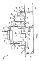
- Figure 1 is a flow diagram of a preferred apparatus of the present invention for controlling ultrafiltration during hemodialysis.
- Figure 2 is a flow diagram of a preferred apparatus of the present invention for controlling infusion during hemodialysis.
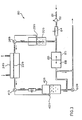
- Figure 3 is a flow diagram of an alternative embodiment of an apparatus of the present invention for controlling ultrafiltration during hemodialysis.
- Apparatus 10 comprises a continuous loop or circuit flow path 12 for dialysate originating with a fresh dialysate supply line 14 and terminating in a spent dialysate removal line 15.
- Supply line 14 is connectable to the host dialysis machine so that fresh dialysate may be delivered to apparatus 10.
- removal line 15 is connectable to the same host dialysis machine and provides a mechanism for draining spent dialysate from the apparatus herein described.
- all fresh dialysate enters flow path 12 through supply line 14 while all spent dialysate leaves the closed loop flow path by being drained from removal line 15.
- a reservoir 16 Connected immediately to supply 14 is a reservoir 16 which holds a quantity of fresh dialysate which is delivered thereto.
- An overflow line 18 is provided in case the level of fresh dialysate inside the reservoir exceeds a pre-determined level. This overflow line 18 is connected to removal line 15 so that excess dialysate is readily drained from the flow path.
- An air vent 19 is included in overflow line 18 near the interface with the first receptacle to control the pressures influencing the operation of the pumps to be described hereinafter.
- a first receptacle 20 is included in the continuous loop flow path and is in fluid communication with reservoir 16 by virtue of flow line 21.
- a first metering pump 22, in flow line 21, is provided to withdraw fresh dialysate from the reservoir and deliver it to the first receptacle 20.
- Pump 22 is intended to operate at a fixed rate of speed for delivering fresh dialysate at a pre-determined, controlled rate to the receptacle.
- the flow path extends to the dialysate section of a hemodialyzer 24 by virtue of flow line 25 which provides fluid communication between the first receptacle and an inlet dialysate port 26 of the hemodialyzer.
- Pump 28 is preferably a variable flow pump which is controllable to adjust the rate of flow of the fresh dialysate toward the hemodialyzer.
- the reason that variable rates of fresh dialysate delivery are required is related to the level or volume of fresh dialysate in the first receptacle.
- the level of fresh dialysate in the first receptacle should be maintained relatively constant, preferably at a predetermined level.
- a liquid sensing device 29 is included in first receptacle 20 to detect the level or volume of liquid contained therein.
- Sensing device 29 is preferably electrically connected to pump 28 so that the flow from pump 28 can be varied as a function of the level of liquid inside the first receptacle. For instance, if the level of liquid is lower than a pre-determined level, the flow from pump 28 would be decreased whereby the level of liquid in the first receptacle would increase; conversely, if the level of liquid is higher than the pre-determined level, sensing device 29 would control the flow from pump 28 to increase the flow to readjust the level downward toward the pre-determined level.
- Hemodialyzer 24 may be any of the well-known dialyzers useful for hemodialysis and including a membrane 32 therein adapted to remove waste materials and ultrafiltrate from the blood.
- Fresh dialysate enters the hemodialyzer through dialysate inlet port 26, and after collecting waste materials and ultrafiltrate from the blood, spent dialysate exits the hemodialyzer through dialysate outlet port 34.
- the hemodialyzer includes a blood inlet port 35 through which blood from a hemodialysis patient enters.
- a blood outlet port 36 is provided on the hemodialyzer to return blood, from which waste materials and ultrafiltrate have been removed, to the patient.
- Spent dialysate is withdrawn from hemodialyzer 24 through flow line 38 and is delivered into a second receptacle 40.
- a second variable rate pump 41 which is provided in flow line 39.
- Pump 41 is preferably, but not necessarily, similar to pump 28, and has its flow controlled by virtue of a liquid sensing device 42 which, once again, is similar to sensing device 29.
- Sensing device 42 senses the level or volume of spent dialysate inside receptacle 40 and is electrically connected to pump 41 to adjust its flow during in-line operation to assure that the level of spent dialysate in the second receptacle is maintained at a relatively constant, pre-determined level.
- the pre-determined levels to be sensed in both receptacles are tightly controlled, thereby contributing to mass balance of dialysate entering and leaving the hemodialyzer.
- Spent dialysate is withdrawn from second receptacle 40 through a flow line 44 which is in fluid communication with spent dialysate removal line 15.
- a second, preferably, but not necessarily, fixed rate pump 45 is positioned in flow line 44 to withdraw spent dialysate from the second receptacle at substantially the same controlled rate that pump 22 withdraws fresh dialysate from the reservoir for delivery to the first receptacle.
- An air vent 46 similar to air vent 19, is included in removal line 15 near the output side of pump 45 for regulating pressures influencing the operation of the pumps.
- Matching outputs and calibration of pumps 22 and 45 may be accomplished in a number of ways.
- One preferable technique is illustrated in Figure 1.
- Receptacles 20 and 40 are by-passed by closing valves 48 and 49 in flow lines 21 and 44, respectively. Closing these valves opens shunt lines 50 and 51 connected to a calibration chamber 52.
- a calibration bleed-off line 55 is connected at one end to flow line 21 at the output side of pump 22 and is connected on the other end to reservoir 16.
- a valve 56 is opened while pump 22 is operating at a greater speed than pump 45, and while shunt lines 50 and 51 are opened. Calibration is achieved by bleeding-off excess fresh dialysate through port 58 until the level of liquid in sight tube 54 remains at a constant level. Valves 48, 49 and 56 are then closed with the assurance that the output of pump 22 substantially balances the intake of pump 45.
- the respective pumps may be balanced in other ways, including the use of the same motor to operate both pumps.
- a variable restriction may be placed in the dialysate flow path to restrict the flow of fresh or spent dialysate flow therethrough, particularly when pump 22 operates at a higher speed than pump 45.
- ultrafiltrate removal pump 60 is positioned in a flow line 61 extending between first receptacle 20 and spent dialysate removal line 15. By withdrawing a controlled amount of fresh dialysate from receptacle 20, the equilibrium of the fresh and spent dialysate is changed thereby causing a withdrawal of ultrafiltrate from the patient's blood.
- the operation of ultrafiltrate pump 60 can be controlled and programmed to withdraw metered quantities of dialysate from the flow path causing ultrafiltrate to be removed from the patient's blood in known and calculable amounts. Operation of the apparatus of Figure 1 will not be described.
- apparatus 10 operates at atmospheric pressure.
- air vents 64 and 65 in receptacles 20 and 40 are provided.
- Fresh dialysate supply line 14 is appropriately connected to the host dialysis machine (not shown) and spent dialysate removal line 15 is also appropriately connected to the host dialysis machine.
- Fresh dialysate, delivered to reservoir 16 from the host machine has been premixed, preheated and degassed as necessary.
- Pumps 22 and 45 have been calibrated, such as described above, so that the output of pump 22 balances the intake of pump 45.
- pump 22 withdraws a controlled amount of fresh dialysate from the reservoir, which typically may be at the rate of 500 ml/min, and delivers the fresh dialysate to receptacle 20.
- Pump 28 withdraws fresh dialysate from receptacle 20 at substantially the same rate that the fresh dialysate is delivered to the first receptacle.
- the level of fresh dialysate in receptacle 20 is held substantially constant in accordance with the level or volume sensing device 29 as described above which controls the flow rate at which pump 28 operates.
- pump 41 withdraws the spent dialysate therefrom and delivers same to receptacle 40.
- level or volume sensing device 42 adjusts the flow from pump 41 to maintain a relatively constant, pre-determined level of spent dialysate in receptacle 40.
- Spent dialysate is removed from the hemodialyzer also at substantially the same rate that fresh dialysate is delivered thereto.
- spent dialysate is withdrawn by virtue of pump 45 whereupon the spent dialysate enters removal line 15 so that it may be drained from the system.
- pump 45 withdraws spent dialysate at substantially the same rate that fresh dialysate is withdrawn by pump 22 from reservoir 16. If pumps 22 and 45 have been matched so that the output of pump 22 substantially matches the intake of pump 45, mass balance of dialysate will be achieved.
- ultrafiltrate removal pump 60 is activated to withdraw a controlled amount of dialysate from receptacle 20. This amount may vary according to the needs and condition of the patient, and may typically range between zero and 300 ml/min.
- an imbalance in the pre-established equilibrium occurs which causes pumps 28 and 41 to increase or decrease flow rates to once again seek the equilibrium of the pre-determined levels of dialysate in the respective receptacles. While this is occurring, a negative or positive pressure is exerted in the dialysate section of the hemodialyzer to effect a withdrawal of ultrafiltrate from the patient's blood across membrane 32.
- This ultrafiltrate enters the dialysate flow patch to substantially balance the amount of dialysate withdrawn therefrom.
- the amount of ultrafiltrate removed from the patient's blood matches the amount of dialysate withdrawn from either of the receptacles. It can be seen that this mechanism of controlling ultrafiltration during hemodialysis is simply constructed, straight-forward in use and performs accurately, particularly since accuracy is not affected by air in the system.
- FIG. 1 While the embodiment of Figure 1 has been described as preferably operating at atmospheric pressure, it is not limited to operation at that pressure.
- air vents 64 and 65 in receptacles 20 and 40, respectively, may be closed to provide a substantially air-tight closed circuit section between pump 22 and pump 45.
- the ultrafiltration apparatus of Figure 1 may be operated at a chosen pressure within the design capabilities of the system. If other than atmospheric pressures operation is selected, however, the pressures inside receptacles 20 and 40 should be tightly controlled.
- An air trap (not shown) should also be included in the line between pump 41 and receptacle 40.
- sensing devices 29 and 42 could be selected could be selected to sense pressures inside the respective receptacles. Use of pressure sensors would then be compatible with operation of the apparatus at a pressure other than atmospheric pressure.
- variable rate pumps 28 and 41 there are also other techniques for producing mass balance of the fresh and spent dialysate besides the preferable variable rate pumps as described in conjuction with Figure 1.
- the speed of the pumps may be held constant.
- Flow control may be established by way of variable recirculating loops (not shown) which may contain control valves which are regulated by the levels of liquid in the respective receptacles.
- Other techniques are also within the purview of the present invention.
- infusion apparatus 70 is the same as ultrafiltration apparatus 10 as illustrated in Figure 1. Accordingly, the elements or components of apparatus 70 which similarly correspond to elements of apparatus 10 have been designated with the same numerals as found in apparatus 10 followed by the suffix "a.” The modification of apparatus 10 lies essentially in the arrangement of infusate delivery pump 72.
- pump 72 is not connected to removal line 15a in the same fashion as ultrafiltrate pump 60 is connected to removal line 15 as described above.
- an infusate container 74 for holding infusate is provided and a flow line 75 is in fluid communication between container 74 and first receptacle 20a.
- Infusate delivery pump 72 which operates in reverse fashion from ultrafiltrate removal pump 60, withdraws infusate from container 74 in a controlled amount and supplies this infusate to the fresh dialysate in first receptacle 20a. Once mass balance between the fresh and spent dialysate has been achieved, addition of the liquid infusate into receptacle 20a will change the equilibrium characteristics.
- variable speed pump 28 may be replaced with a control valve. While this approach may be less expensive than the use of the variable speed pump, some sacrifice in operation is necessary. Specifically, if a control valve is used, zero ultrafiltration may not be possible to achieve. However, this may not be a significant sacrifice because most dialysis procedures today are performed with this limitation.
- Another alternative includes deleting both preferably fixed rate pumps 22 and 45 and replacing them with metering valves or flow restrictors. In this approach, judicious rearrangement of the receptacles will permit gravity to perform the pumping operation that pumps 22 and 45 had assumed.
- reservoir 16 may function without overflow line 18 connected to removal line 15.
- a control valve upstream of the reservoir, can be used to regulate the amount of fresh dialysate within the reservoir. This control valve would operate in similar fashion to sensing devices 29 and 42.
- Double acting piston 85 similar to that described in U.S. Patent No. 4,209,391, includes two chambers 86 and 88, respectively.
- Chamber 86 regulates the delivery of fresh dialysate into first receptacle 20b, while chamber 88 regulates the withdrawal of spent dialysate from second receptacle 40b.
- Ultrafiltration pump 60b may be driven by the action of variable speed pump 41b which may also drive the inlet of chamber 88 of the double acting piston.
- the present invention controls the rate of fluid removal from, or addition to, the patient by accurately metering dialysate delivery to and from the hemodialyzer preferably by way of matched pumps.
- the system of the present invention is based on maintaining relatively constant levels of fresh dialysate and spent dialysate in pre- and post-dialyzer receptacles which may be maintained at atmospheric pressure for ease and convenience of operation.
Applications Claiming Priority (3)
| Application Number | Priority Date | Filing Date | Title |
|---|---|---|---|
| US56232883A | 1983-12-16 | 1983-12-16 | |
| US06/873,264 US4747950A (en) | 1983-12-16 | 1986-06-06 | Method and apparatus for controlled ultrafiltration during hemodialysis |
| PCT/US1988/001710 WO1989011320A1 (en) | 1983-12-16 | 1988-05-24 | Hemodialysis method and apparatus with controlled ultrafiltration |
Publications (1)
| Publication Number | Publication Date |
|---|---|
| EP0343267A1 true EP0343267A1 (de) | 1989-11-29 |
Family
ID=27072922
Family Applications (2)
| Application Number | Title | Priority Date | Filing Date |
|---|---|---|---|
| EP19880108276 Withdrawn EP0343267A1 (de) | 1983-12-16 | 1988-05-24 | Methode und Gerät zur Regelung der Ultrafiltration während einer Hemodialyse |
| EP19880906271 Pending EP0377577A4 (en) | 1983-12-16 | 1988-05-24 | Hemodialysis method and apparatus with controlled ultrafiltration |
Family Applications After (1)
| Application Number | Title | Priority Date | Filing Date |
|---|---|---|---|
| EP19880906271 Pending EP0377577A4 (en) | 1983-12-16 | 1988-05-24 | Hemodialysis method and apparatus with controlled ultrafiltration |
Country Status (5)
| Country | Link |
|---|---|
| US (1) | US4747950A (de) |
| EP (2) | EP0343267A1 (de) |
| JP (1) | JPH02504348A (de) |
| AU (1) | AU624332B2 (de) |
| WO (1) | WO1989011320A1 (de) |
Cited By (4)
| Publication number | Priority date | Publication date | Assignee | Title |
|---|---|---|---|---|
| WO1992011878A1 (en) * | 1991-01-03 | 1992-07-23 | Robert Smith Pedersen | Hemodialysis apparatus |
| US6703073B2 (en) | 2000-02-25 | 2004-03-09 | Tesa Ag | Polar acrylic pressure-sensitive adhesive compositions |
| DE102009048561A1 (de) * | 2009-10-07 | 2011-04-14 | Fresenius Medical Care Deutschland Gmbh | Vorrichtung zur Dialysebehandlung und Verfahren zum Bilanzieren von frischer und verbrauchter Dialysierflüssigkeit |
| US9814818B2 (en) | 2009-09-29 | 2017-11-14 | Fresenius Medical Care Deutschland Gmbh | Device and method for detecting blood or blood constituents in the liquid system of a device for extracorporeal blood treatment |
Families Citing this family (23)
| Publication number | Priority date | Publication date | Assignee | Title |
|---|---|---|---|---|
| FR2597753B1 (fr) * | 1986-04-25 | 1990-09-28 | Hospal Ind | Rein artificiel avec dispositif de controle des quantites de liquide circulant dans le circuit de liquide de dialyse |
| US5247434A (en) * | 1991-04-19 | 1993-09-21 | Althin Medical, Inc. | Method and apparatus for kidney dialysis |
| US5486286A (en) * | 1991-04-19 | 1996-01-23 | Althin Medical, Inc. | Apparatus for performing a self-test of kidney dialysis membrane |
| SE510511C2 (sv) * | 1997-12-16 | 1999-05-31 | Gambro Lundia Ab | System och förfarande för övervakning av en doseringspump i en dialysmaskin |
| US6331252B1 (en) | 1998-07-31 | 2001-12-18 | Baxter International Inc. | Methods for priming a blood compartment of a hemodialyzer |
| US7241272B2 (en) | 2001-11-13 | 2007-07-10 | Baxter International Inc. | Method and composition for removing uremic toxins in dialysis processes |
| DE60336724D1 (de) | 2002-07-19 | 2011-05-26 | Baxter Healthcare Sa | System für die peritonealdialyse |
| US7029456B2 (en) * | 2003-10-15 | 2006-04-18 | Baxter International Inc. | Medical fluid therapy flow balancing and synchronization system |
| US8029454B2 (en) | 2003-11-05 | 2011-10-04 | Baxter International Inc. | High convection home hemodialysis/hemofiltration and sorbent system |
| US8092414B2 (en) | 2005-11-09 | 2012-01-10 | Nxstage Medical, Inc. | Diaphragm pressure pod for medical fluids |
| US8114276B2 (en) | 2007-10-24 | 2012-02-14 | Baxter International Inc. | Personal hemodialysis system |
| ES2542999T5 (es) | 2007-10-24 | 2024-02-23 | Nikkiso Co Ltd | Optimización del aclaramiento para moléculas unidas a proteínas usando terapia de filtración en cascada |
| US9415150B2 (en) | 2007-11-09 | 2016-08-16 | Baxter Healthcare S.A. | Balanced flow dialysis machine |
| EP2343092B2 (de) | 2009-12-22 | 2016-07-13 | Gambro Lundia AB | Verfahren und Vorrichtung zur Steuerung einer Strömungsrate in einer Flüssigkeitstransportleitung einer medizinischen Vorrichtung |
| CN103619372A (zh) | 2011-03-23 | 2014-03-05 | 纳科斯达格医药股份有限公司 | 腹膜透析系统、装置和方法 |
| US9551625B2 (en) | 2011-05-31 | 2017-01-24 | Nxstage Medical, Inc. | Pressure measurement devices, methods, and systems |
| EP2644259A1 (de) * | 2012-03-29 | 2013-10-02 | Roche Diagniostics GmbH | Mikroflussfiltrationssystem und Flussfiltrationsverfahren |
| WO2014076519A1 (fr) * | 2012-10-29 | 2014-05-22 | Debiotech S.A. | Dispositif de traitement extra corporel du sang |
| US10328192B2 (en) | 2013-07-15 | 2019-06-25 | Gambro Lundia Ab | Relative pump calibration for ultrafiltration control in a dialysis apparatus |
| CN104470553B (zh) * | 2013-07-15 | 2017-02-22 | 甘布罗伦迪亚股份公司 | 用于透析装置中的超滤控制的单泵校准 |
| US10195418B2 (en) | 2014-10-10 | 2019-02-05 | Nxstage Medical, Inc. | Pinch clamp devices, methods, and systems |
| JP6873838B2 (ja) * | 2017-06-20 | 2021-05-19 | 日機装株式会社 | 血液浄化装置 |
| US11207454B2 (en) | 2018-02-28 | 2021-12-28 | Nxstage Medical, Inc. | Fluid preparation and treatment devices methods and systems |
Citations (4)
| Publication number | Priority date | Publication date | Assignee | Title |
|---|---|---|---|---|
| BE739297A (de) * | 1969-09-24 | 1970-03-02 | ||
| FR2434624A1 (fr) * | 1978-09-02 | 1980-03-28 | Fresenius Chem Pharm Ind | Appareil de commande d'ultrafiltration dans l'hemodialyse |
| DE8117448U1 (de) * | 1981-06-12 | 1981-11-12 | Schlick, Bernhard, 6800 Mannheim | Vorrichtung zur Hämodialysebehandlung |
| EP0104460A2 (de) * | 1982-08-31 | 1984-04-04 | CD Medical Inc. | Hämodialysevorrichtung |
Family Cites Families (8)
| Publication number | Priority date | Publication date | Assignee | Title |
|---|---|---|---|---|
| US3757947A (en) * | 1969-06-25 | 1973-09-11 | Univ Washington | Research test dialyzer system |
| FR2344297A1 (fr) * | 1976-03-15 | 1977-10-14 | Rhone Poulenc Ind | Perfectionnement aux reins artificiels |
| US4178240A (en) * | 1976-05-17 | 1979-12-11 | Pinkerton Harry E | Fluid handling system |
| FR2397197A1 (en) * | 1978-11-03 | 1979-02-09 | Sodip Sa | Extracorporeal blood purificn. - by simultaneous haemodialysis and haemo-filtration with incorporated flow ewuilibrantion |
| FR2457694A1 (fr) * | 1979-06-01 | 1980-12-26 | Nice Cote Azur Assoc Rgle Aide | Procede d'hemofiltration et appareil a fonctionnement automatique pour la mise en oeuvre de ce procede |
| JPS56132961A (en) * | 1980-03-22 | 1981-10-17 | Daicel Ltd | Artificial kidney device |
| US4486303A (en) * | 1981-10-06 | 1984-12-04 | Brous Donald W | Ultrafiltration in hemodialysis |
| FR2597753B1 (fr) * | 1986-04-25 | 1990-09-28 | Hospal Ind | Rein artificiel avec dispositif de controle des quantites de liquide circulant dans le circuit de liquide de dialyse |
-
1986
- 1986-06-06 US US06/873,264 patent/US4747950A/en not_active Expired - Fee Related
-
1988
- 1988-05-24 EP EP19880108276 patent/EP0343267A1/de not_active Withdrawn
- 1988-05-24 WO PCT/US1988/001710 patent/WO1989011320A1/en not_active Application Discontinuation
- 1988-05-24 EP EP19880906271 patent/EP0377577A4/en active Pending
- 1988-05-24 JP JP63505759A patent/JPH02504348A/ja active Pending
- 1988-05-24 AU AU19842/88A patent/AU624332B2/en not_active Expired - Fee Related
Patent Citations (4)
| Publication number | Priority date | Publication date | Assignee | Title |
|---|---|---|---|---|
| BE739297A (de) * | 1969-09-24 | 1970-03-02 | ||
| FR2434624A1 (fr) * | 1978-09-02 | 1980-03-28 | Fresenius Chem Pharm Ind | Appareil de commande d'ultrafiltration dans l'hemodialyse |
| DE8117448U1 (de) * | 1981-06-12 | 1981-11-12 | Schlick, Bernhard, 6800 Mannheim | Vorrichtung zur Hämodialysebehandlung |
| EP0104460A2 (de) * | 1982-08-31 | 1984-04-04 | CD Medical Inc. | Hämodialysevorrichtung |
Cited By (5)
| Publication number | Priority date | Publication date | Assignee | Title |
|---|---|---|---|---|
| WO1992011878A1 (en) * | 1991-01-03 | 1992-07-23 | Robert Smith Pedersen | Hemodialysis apparatus |
| US6703073B2 (en) | 2000-02-25 | 2004-03-09 | Tesa Ag | Polar acrylic pressure-sensitive adhesive compositions |
| US9814818B2 (en) | 2009-09-29 | 2017-11-14 | Fresenius Medical Care Deutschland Gmbh | Device and method for detecting blood or blood constituents in the liquid system of a device for extracorporeal blood treatment |
| DE102009048561A1 (de) * | 2009-10-07 | 2011-04-14 | Fresenius Medical Care Deutschland Gmbh | Vorrichtung zur Dialysebehandlung und Verfahren zum Bilanzieren von frischer und verbrauchter Dialysierflüssigkeit |
| DE102009048561B4 (de) * | 2009-10-07 | 2017-01-26 | Fresenius Medical Care Deutschland Gmbh | Vorrichtung zur Dialysebehandlung |
Also Published As
| Publication number | Publication date |
|---|---|
| US4747950A (en) | 1988-05-31 |
| AU1984288A (en) | 1989-12-12 |
| JPH02504348A (ja) | 1990-12-13 |
| AU624332B2 (en) | 1992-06-11 |
| WO1989011320A1 (en) | 1989-11-30 |
| EP0377577A4 (en) | 1991-04-03 |
| EP0377577A1 (de) | 1990-07-18 |
Similar Documents
| Publication | Publication Date | Title |
|---|---|---|
| AU624332B2 (en) | Hemodialysis method and apparatus with controlled ultrafiltration | |
| EP1434646B2 (de) | Vorrichtung zur steuerung eines dialysegerätes | |
| US4708802A (en) | Apparatus for hemodiafiltration | |
| US6156002A (en) | Method of measuring the efficiency of mass and energy transfer in hemodialysis | |
| EP1424089B1 (de) | Dialysemaschine | |
| US7540958B2 (en) | Device for controlling blood circulation for a single needle circuit | |
| US7563240B2 (en) | Haemodialysis device | |
| EP1729836B1 (de) | Blutbehandlungsausrüstung und softwareprogramm für die infusionskontrolle | |
| US4728433A (en) | Ultrafiltration regulation by differential weighing | |
| US9220830B2 (en) | Apparatus for extracorporeal blood treatment | |
| CA2495561C (en) | Blood purifying device and method of operating the same | |
| US6824524B1 (en) | Tubing for the extracorporal purification of the blood and use thereof | |
| US3990973A (en) | Apparatus for measuring ultrafiltration rate | |
| JPS6129361A (ja) | 血液透析装置 | |
| US10220130B2 (en) | Device and method for balancing between an inflow into and an outflow out of a medical treatment device | |
| JP3180309B2 (ja) | 持続的血液浄化用装置 | |
| CN110891625B (zh) | 用于校准用于血液治疗的泵的方法和装置 | |
| EP1722837B1 (de) | Einzelnadelvorrichtung für die extrakorporale behandlung von blut | |
| JPH0910304A (ja) | 持続的血液浄化用装置 | |
| JPH02239870A (ja) | 血液透析装置の除水量制御装置 | |
| JPS6329655A (ja) | 人工腎臓装置 | |
| JPS6226804B2 (de) | ||
| CN117479966A (zh) | 用于体外血液处理的设备 | |
| JPS62120858A (ja) | 開放式患者流体処理方法 | |
| JPS5995053A (ja) | 限外「ろ」過量の測定装置 |
Legal Events
| Date | Code | Title | Description |
|---|---|---|---|
| PUAI | Public reference made under article 153(3) epc to a published international application that has entered the european phase |
Free format text: ORIGINAL CODE: 0009012 |
|
| 17P | Request for examination filed |
Effective date: 19890706 |
|
| AK | Designated contracting states |
Kind code of ref document: A1 Designated state(s): ES |
|
| RBV | Designated contracting states (corrected) |
Designated state(s): AT BE CH DE ES FR GB IT LI LU NL SE |
|
| XX | Miscellaneous (additional remarks) |
Free format text: VERBUNDEN MIT 88906271.7/0377577 (EUROPAEISCHE ANMELDENUMMER/VEROEFFENTLICHUNGSNUMMER) DURCH ENTSCHEIDUNG VOM 03.07.91. |
|
| 17Q | First examination report despatched |
Effective date: 19911025 |
|
| RAP1 | Party data changed (applicant data changed or rights of an application transferred) |
Owner name: ALTHIN CD MEDICAL, INC. |
|
| RAP3 | Party data changed (applicant data changed or rights of an application transferred) |
Owner name: ALTHIN CD MEDICAL, INC. |
|
| STAA | Information on the status of an ep patent application or granted ep patent |
Free format text: STATUS: THE APPLICATION IS DEEMED TO BE WITHDRAWN |
|
| 18D | Application deemed to be withdrawn |
Effective date: 19930107 |