EP0343033A1 - Aufbau zum Messen und Prüfen von frischen Betonprodukten - Google Patents
Aufbau zum Messen und Prüfen von frischen Betonprodukten Download PDFInfo
- Publication number
- EP0343033A1 EP0343033A1 EP89401250A EP89401250A EP0343033A1 EP 0343033 A1 EP0343033 A1 EP 0343033A1 EP 89401250 A EP89401250 A EP 89401250A EP 89401250 A EP89401250 A EP 89401250A EP 0343033 A1 EP0343033 A1 EP 0343033A1
- Authority
- EP
- European Patent Office
- Prior art keywords
- products
- probe
- sensor
- support
- upper face
- Prior art date
- Legal status (The legal status is an assumption and is not a legal conclusion. Google has not performed a legal analysis and makes no representation as to the accuracy of the status listed.)
- Withdrawn
Links
- 239000000523 sample Substances 0.000 claims abstract description 69
- 238000012545 processing Methods 0.000 claims abstract description 16
- 238000000465 moulding Methods 0.000 claims description 15
- 238000005266 casting Methods 0.000 claims description 6
- 238000006073 displacement reaction Methods 0.000 claims description 6
- 230000005855 radiation Effects 0.000 claims description 4
- 238000005259 measurement Methods 0.000 description 23
- 238000004519 manufacturing process Methods 0.000 description 11
- 238000009434 installation Methods 0.000 description 7
- 238000012546 transfer Methods 0.000 description 6
- 238000003860 storage Methods 0.000 description 5
- 230000007547 defect Effects 0.000 description 3
- 238000001514 detection method Methods 0.000 description 3
- 238000002604 ultrasonography Methods 0.000 description 3
- 230000002950 deficient Effects 0.000 description 2
- 238000010586 diagram Methods 0.000 description 2
- 238000012986 modification Methods 0.000 description 2
- 230000004048 modification Effects 0.000 description 2
- 238000012935 Averaging Methods 0.000 description 1
- 241000237536 Mytilus edulis Species 0.000 description 1
- 230000002159 abnormal effect Effects 0.000 description 1
- 239000004020 conductor Substances 0.000 description 1
- 235000020638 mussel Nutrition 0.000 description 1
- 230000003287 optical effect Effects 0.000 description 1
- 230000000284 resting effect Effects 0.000 description 1
- 238000005096 rolling process Methods 0.000 description 1
Images

Classifications
-
- G—PHYSICS
- G01—MEASURING; TESTING
- G01B—MEASURING LENGTH, THICKNESS OR SIMILAR LINEAR DIMENSIONS; MEASURING ANGLES; MEASURING AREAS; MEASURING IRREGULARITIES OF SURFACES OR CONTOURS
- G01B17/00—Measuring arrangements characterised by the use of infrasonic, sonic or ultrasonic vibrations
-
- B—PERFORMING OPERATIONS; TRANSPORTING
- B28—WORKING CEMENT, CLAY, OR STONE
- B28B—SHAPING CLAY OR OTHER CERAMIC COMPOSITIONS; SHAPING SLAG; SHAPING MIXTURES CONTAINING CEMENTITIOUS MATERIAL, e.g. PLASTER
- B28B17/00—Details of, or accessories for, apparatus for shaping the material; Auxiliary measures taken in connection with such shaping
- B28B17/0063—Control arrangements
- B28B17/0072—Product control or inspection
-
- G—PHYSICS
- G01—MEASURING; TESTING
- G01B—MEASURING LENGTH, THICKNESS OR SIMILAR LINEAR DIMENSIONS; MEASURING ANGLES; MEASURING AREAS; MEASURING IRREGULARITIES OF SURFACES OR CONTOURS
- G01B21/00—Measuring arrangements or details thereof, where the measuring technique is not covered by the other groups of this subclass, unspecified or not relevant
- G01B21/02—Measuring arrangements or details thereof, where the measuring technique is not covered by the other groups of this subclass, unspecified or not relevant for measuring length, width, or thickness
Definitions
- the invention relates to an assembly for measuring and controlling the size of fresh concrete products carried by a horizontal support, such as a board, mold base, etc., at the outlet of a manufacturing machine, and more particularly an assembly of the type comprising at least one sensor making it possible to determine a dimension of the products carried by the support, by difference between the height of the upper face of the products and the height of the upper face of the support on which the products rest, or of any other reference.
- a dimensional check of concrete products such as blocks, interjoists, pavers, curbs, prestressed pre-slabs, ... is carried out at the manufacturing stage to ensure that their dimensions are within a predetermined range. It is important that this check is carried out as soon as possible after manufacture in order to intervene on the machine as quickly as possible.
- document FR-A-2 586 610 discloses a measurement and control assembly of the aforementioned type placed at the outlet of the molding machine and comprising roller feelers which explore by contact the upper face of the products and the face upper of the support board in order to provide, by difference, information representative of the dimension of the products between their lower and upper faces.
- contact roller probes require a good surface condition of the explored parts and is only possible with products that are not very fragile or not deformable. However, this is not always the case in the case of fresh concrete products, in particular for products with thin walls offering to the roller of the probe narrow, brittle and often uneven upper rolling surfaces.
- the support on which the products rest also has an uneven upper face, in particular due to the inevitable presence of debris.
- the object of the present invention is to provide a measurement and control unit capable of measuring a dimension of fresh concrete products in the state in which they are presented on their support at the end of manufacture without meeting the drawbacks. cited above.
- the or each sensor is a contactless sensor comprising a transmitting and receiving probe d '' radiation capable of providing a signal representative of the distance between the probe and a surface located opposite the probe, the or each probe is arranged so as to supply by means of the or each sensor first information representative of the height of an upper face of at least one product carried by the support, at different points on this upper face, and second information representative of the height of the upper face of the support on which the products rest, at different points thereof, the first and second information being obtained during a relative scrolling between the or each probe and the support on which are based on one or more products, and -
- the or each sensor is connected to a processing circuit receiving the first and second information and comprising means for calculating the desired dimension from the first and second information.
- the use of distance sensors using radiation such as ultrasonic radiation or a laser beam allows a measurement of the height of the upper face of the products without contact, so that the measurement and control assembly according to the invention can be used with fresh concrete products, even fragile, brittle or deformable.
- the height of the upper face of the products and the height of the upper face of the support on which the products rest, or of any other reference representative of the height of the support, are measured continuously during the relative scrolling between the or each probe and the support on which the products are based.
- the desired dimension can be obtained by calculating an average value from the information received by the processing circuit.
- the measurement and control assembly may include at least a first sensor having a probe located facing an upper face of a product carried by the board and a second sensor having a probe located facing the upper face of the support outside of the area thereof occupied by the products, during the relative scrolling between the probes and the support.
- the first and second height information is then provided respectively by the first sensor and the second sensor.
- Height measurements can be carried out during the transfer of the products onto a board between a molding machine and a next station in the product manufacturing installation, for example, for products produced on vibrating presses, a pre-storage elevator.
- the relative displacement between the probes and the board is then produced by the transfer movement of the board with regard to the probes.
- the measurement and control device according to the invention can then be integrated into the product manufacturing installation without any modification of this installation or of the manufacturing process since the movement of transfer of the products by the board does not have to be interrupted.
- a single ultrasonic distance sensor may be provided.
- the probe is then placed or moved to be alternately or successively opposite an upper face of the products or the upper surface of the product support board, during the relative scrolling between the probe and the board.
- a first possibility consists in placing the probe in a location such that, during the transfer movement of the board at the outlet of the molding machine, the probe is alternately opposite the upper faces of the walls of the product and opposite the board. , through the cells of the product when they open out, between the walls of the latter.
- Another possibility consists in mounting the probe on a mobile support so as to sweep successively an upper face of a product carried by the board and the upper face of the board, or vice versa.
- Measuring the height of an upper face of a product carried by the board is generally sufficient to give a representative indication of the size not only of this product, but also of other products molded simultaneously and carried by the same board.
- the upper face of the product located opposite the probe is then the one whose height has the greatest probability of being affected by a defect or an incident occurring in the molding machine, such as for example a mold filling defect.
- the heights of the upper faces of several walls of the same product or of walls of different products carried by the same board can be measured by means of a sensor whose probe is movable transversely relative to the direction of relative travel. between the probe (s) and the board.
- the measurement and control assembly according to the invention can also be mounted on mobile machines for casting slabs, on the casting tracks (in particular in prestressing).
- the height measurement of the slabs is then preferably carried out by means of at least three fixed sensors mounted at the rear of the machine. At least two first sensors each have a probe located opposite the upper face of the product, these probes being widely spaced from each other due to the large width of the product.
- a second sensor has a probe located opposite the bottom of the mold or any other reference. The relative displacement between the probes and the mold base is given by the advance of the machine on its running rails.
- the circuit for processing the information supplied by the or each sensor includes means for comparing the measured dimension with one or more threshold values so as to be able to trigger an alarm and order the stopping of the molding machine. or pouring when, for example, the dimension measured is less than a predetermined minimum value.
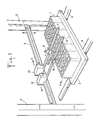
- the measurement and control assembly is arranged on the path of fresh concrete products 1, such as blocks, between a molding machine (not shown) and a next station in the installation.
- Manufacturing products for example a pre-storage elevator 2.
- the demolded products 1 are supported by a horizontal board 3.
- the transfer of the products 1 in the horizontal direction X between the molding machine and the pre-storage elevator is ensured by means of a conveyor 4.
- the measurement and control assembly comprises two ultrasonic distance sensors mounted on a horizontal crosspiece 5 fixed for example to the frame of the prestocking elevator and extending in direction Y perpendicular to the direction X of movement of the products 1.
- Each sensor comprises a probe 10, 11 emitting-receiving ultrasound connected to a housing, respectively 12, 13 by means of flexible conductors.
- Each housing 12, 13 comprises the electronic circuits necessary, on the one hand, for exciting the associated probe to cause the emission of ultrasound and, on the other hand, for processing the signals produced by the probe in response to reception of the ultrasound reflected by a surface located opposite the probe, so as to deliver, for example in digital form, a signal representative of the distance between the probe and the surface located opposite the latter.
- Ultrasonic distance sensors of this type are known.
- the sensors are provided with means for compensating for drifts of thermal origin, which makes it possible to integrate them without problem into an installation where the outside temperature generally prevails, that is to say a temperature subject to strong variations.
- the ultrasonic sensors can be replaced by laser optical triangulation distance sensors such as for example those offered by the Japanese company Matsuchita under the reference MQLA1S1AC240VH01.
- This type of sensor makes it possible to measure distances between 50 and 100 mm with an accuracy of the order of half a millimeter, at a frequency of 100 Hz and with compensation for thermal drifts.
- Each sensor is mounted on an horizontal arm or fork 6, 7 carried by the cross-member 5 and extend perpendicularly to the latter, in the direction of the molding machine.
- the probe 10 of the first sensor is mounted on the arm 6 in an adjustable position along the latter, while the associated housing 12 is mounted on the same arm, at the end of the latter fixed to the cross-member 5.
- the position of the arm 6 along the crosspiece 5 is adjustable so that the probe 10 is vertical to the upper surface of the board 3, outside the area thereof occupied by the products 1, during the displacement of the board in the direction of the pre-storage elevator.
- the probe 11 of the second sensor is mounted on the arm 7 in an adjustable position along the latter, while the associated housing 13 is mounted on the same arm, at the end of the latter fixed to the cross-member 5.
- the position of the arm 7 along the cross-member 5 is adjustable so that the probe 11 is located vertically on the upper face of a wall of a product 1 carried by the board when it moves towards the 'pre-storage elevator.
- the sensors provide information representative of the distance between the probe 10 and the upper face of the board 3 and of the distance between the probe 11 and the upper face of the product carried by the board opposite this probe, that is to say say information representative of the heights of these upper faces.
- the location of the probe 11 will be chosen to measure the dimension of the product which has the highest probability of being defective in the event of an incident occurring during molding, such as example, incorrect filling of the mold.
- the information provided by the sensors is transmitted to a processing circuit 20.
- the same information can also be sent to digital display devices 14, 15 which directly indicate the distances measured by the sensors.
- These display devices are, for example, those proposed by the aforementioned company Honeywell S.A. for use with the sensors of the "Microsonic" 942 series.
- the processing circuit 20 is a microprocessor circuit to which terminals such as a console 22 provided with a keyboard and a printer 24 can be connected, as well as an alarm circuit 26.
- the digital information delivered by the sensors is received at a measurement frequency of several tens of Hertz. Given the horizontal dimension of the board and the products in the direction of their travel in relation to the probes, the travel speed and the surface condition, we thus have a measurement by exploration distance of several millimeters. It is then possible to envisage a statistical processing of the digital information received in order to get rid of erroneous values due in particular to the presence of concrete debris, surface irregularities of the board or of the products.
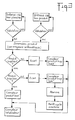
- FIG. 3 illustrates an example of operations carried out by the processing circuit under the control of permanently recorded programs.
- the digital information representative of the distance between the probe 10 and the board 3 is validated after checking that they are within a predefined range, this in order to eliminate any manifestly abnormal values. The same is true for digital information representative of the distance between the probe 11 and the upper face of the product passing opposite the probe.
- the statistical processing carried out on the validated digital information consists, for example, of averaging.
- the dimension sought is calculated by the difference between the arithmetic means obtained for the distances between probe and board and between probe and product.
- the detection of a product that is too low controls the emission of an alarm, for example an audible alarm, and the stopping of the cycle in progress of the molding machine, the defect observed presumably coming from a defective filling. mussels.
- a counter known as a totalizer is incremented with each manufacture of a board of products. A comparison with the sum of the three previous counters makes it possible to qualify the rate of taking into account.
- the calculated dimension, any deviations from the minimum and maximum thresholds and, if applicable, the contents of the counters are displayed on the console 22 or on additional displays and, if desired, edited by means of the printer 24.
- a single distance sensor can be used so that, when the relative scrolling between the board carrying the products and the probe, the latter is alternately or successively opposite the board and a upper side of at least one product.
- the probe could be arranged so as to alternately face an upper face of a transverse wall of a product and an area of the upper surface of the board, through a through-hole of the product. It would also be conceivable to provide a sensor movable in the transverse direction relative to the direction of travel of the board with, optionally, the probe movable along its support arm to successively scan part of the upper surface of the board and at least an upper side of a product.
- measurements can be made on several products carried by the same board.
- at least one of the sensors is mounted on a movable arm along the cross-member 5 to scan the upper faces of several products located side by side on the board.
- the movements are advantageously controlled by means of stepping motors whose electronics are coupled to the processing circuit . It is thus possible to program the trajectory of the mobile sensor exploring the upper face of the product or products according to the geometric configuration of the products on the board.
- a control system is, for example, produced by the French company SOCITEC.
- measurements of the height of prestressed pre-slabs can be carried out by mounting this set on the pre-slab casting machine.
- the width of the products requires the use of at least three fixed sensors mounted on probe rods at the rear of the casting machine, at least two sensors being used to measure the height of the upper face of the product.
Landscapes
- Physics & Mathematics (AREA)
- General Physics & Mathematics (AREA)
- Chemical & Material Sciences (AREA)
- Engineering & Computer Science (AREA)
- Ceramic Engineering (AREA)
- Mechanical Engineering (AREA)
- Investigating Or Analyzing Materials By The Use Of Ultrasonic Waves (AREA)
- Length Measuring Devices With Unspecified Measuring Means (AREA)
- Length Measuring Devices Characterised By Use Of Acoustic Means (AREA)
Applications Claiming Priority (2)
| Application Number | Priority Date | Filing Date | Title |
|---|---|---|---|
| FR8805933 | 1988-05-03 | ||
| FR8805933A FR2631113B1 (fr) | 1988-05-03 | 1988-05-03 | Ensemble de mesure et de controle de produits frais en beton |
Publications (1)
| Publication Number | Publication Date |
|---|---|
| EP0343033A1 true EP0343033A1 (de) | 1989-11-23 |
Family
ID=9365945
Family Applications (1)
| Application Number | Title | Priority Date | Filing Date |
|---|---|---|---|
| EP89401250A Withdrawn EP0343033A1 (de) | 1988-05-03 | 1989-05-03 | Aufbau zum Messen und Prüfen von frischen Betonprodukten |
Country Status (5)
| Country | Link |
|---|---|
| EP (1) | EP0343033A1 (de) |
| DK (1) | DK215089A (de) |
| FI (1) | FI892102A7 (de) |
| FR (1) | FR2631113B1 (de) |
| NO (1) | NO891812L (de) |
Cited By (9)
| Publication number | Priority date | Publication date | Assignee | Title |
|---|---|---|---|---|
| EP0657260A1 (de) * | 1993-12-08 | 1995-06-14 | Betonwerk Lintel GmbH & Co. KG | Verfahren zur Qualitätssicherung bzw. zur Qualitätsüberwachung von geformten Bauelementen |
| DE19527147A1 (de) * | 1994-10-10 | 1996-04-11 | Laeis & Bucher Gmbh | Verfahren und Vorrichtung zur Qualitätsprüfung von Formteilen |
| DE19511324A1 (de) * | 1995-03-28 | 1996-10-10 | Masa Ag | Verfahren und Vorrichtung zur Qualitätsprüfung während der Herstellung von Betonsteinen |
| DE29702402U1 (de) * | 1997-02-12 | 1997-04-10 | ELSAT Elektroanlagen GmbH, 26683 Saterland | Einrichtung zur Qualitätsprüfung von Formkörpern, insbesondere Betonsteinen |
| EP1211511A3 (de) * | 2000-11-07 | 2002-09-25 | Dyckerhoff Aktiengesellschaft | Verfahren zur zerstörungsfreien, automatisierten Festigkeitsbestimmung an Prüfkörpern sowie Prüfvorrichtung zur zerstörungsfreien Festigkeitsbestimmung |
| CN110038666A (zh) * | 2019-05-13 | 2019-07-23 | 闽江师范高等专科学校 | 智能压碎机及工作方法 |
| CN111300630A (zh) * | 2020-03-12 | 2020-06-19 | 浙江吉成新材股份有限公司 | 一种用于等静压处理工艺的装置 |
| CN115183719A (zh) * | 2022-07-06 | 2022-10-14 | 苏州华星光电技术有限公司 | 一种高度测量装置及方法 |
| EP4331797A1 (de) * | 2022-08-23 | 2024-03-06 | HESS Group GmbH | Messeinrichtung für eine rütteleinrichtung einer betonsteinfertigungsanlage und verfahren zur bestimmung des vertikalen abstands zwischen rütteltisch und prallleisten so einer rütteleinrichtung |
Citations (4)
| Publication number | Priority date | Publication date | Assignee | Title |
|---|---|---|---|---|
| DE2709612A1 (de) * | 1977-03-05 | 1978-09-07 | Tonindustrie Prueftechnik Gmbh | Verfahren zur messung der laenge einer wuerfelflaeche eines beton-probewuerfels und vorrichtung zur durchfuehrung des verfahrens |
| US4419384A (en) * | 1982-09-27 | 1983-12-06 | Armstrong World Industries, Inc. | Apparatus and process for ultrasonically identifying and coating articles having differing characteristics |
| DE3237090A1 (de) * | 1982-10-07 | 1984-04-12 | Dyckerhoff & Widmann AG, 8000 München | Verfahren zur pruefung von frischbeton sowie vorrichtung zum durchfuehren des verfahrens |
| FR2586610A1 (fr) * | 1985-08-28 | 1987-03-06 | Passavant Werke | Procede et dispositif pour produire des briquettes possedant un poids specifique apparent constant et des dimensions constantes |
-
1988
- 1988-05-03 FR FR8805933A patent/FR2631113B1/fr not_active Expired - Lifetime
-
1989
- 1989-05-02 DK DK215089A patent/DK215089A/da not_active Application Discontinuation
- 1989-05-02 FI FI892102A patent/FI892102A7/fi not_active IP Right Cessation
- 1989-05-02 NO NO89891812A patent/NO891812L/no unknown
- 1989-05-03 EP EP89401250A patent/EP0343033A1/de not_active Withdrawn
Patent Citations (4)
| Publication number | Priority date | Publication date | Assignee | Title |
|---|---|---|---|---|
| DE2709612A1 (de) * | 1977-03-05 | 1978-09-07 | Tonindustrie Prueftechnik Gmbh | Verfahren zur messung der laenge einer wuerfelflaeche eines beton-probewuerfels und vorrichtung zur durchfuehrung des verfahrens |
| US4419384A (en) * | 1982-09-27 | 1983-12-06 | Armstrong World Industries, Inc. | Apparatus and process for ultrasonically identifying and coating articles having differing characteristics |
| DE3237090A1 (de) * | 1982-10-07 | 1984-04-12 | Dyckerhoff & Widmann AG, 8000 München | Verfahren zur pruefung von frischbeton sowie vorrichtung zum durchfuehren des verfahrens |
| FR2586610A1 (fr) * | 1985-08-28 | 1987-03-06 | Passavant Werke | Procede et dispositif pour produire des briquettes possedant un poids specifique apparent constant et des dimensions constantes |
Cited By (16)
| Publication number | Priority date | Publication date | Assignee | Title |
|---|---|---|---|---|
| EP0657260A1 (de) * | 1993-12-08 | 1995-06-14 | Betonwerk Lintel GmbH & Co. KG | Verfahren zur Qualitätssicherung bzw. zur Qualitätsüberwachung von geformten Bauelementen |
| DE19527147A1 (de) * | 1994-10-10 | 1996-04-11 | Laeis & Bucher Gmbh | Verfahren und Vorrichtung zur Qualitätsprüfung von Formteilen |
| EP0706868A1 (de) * | 1994-10-10 | 1996-04-17 | LAEIS + BUCHER GmbH | Verfahren und Vorrichtung zur Qualitätsprüfung von Formteilen |
| US5748322A (en) * | 1994-10-10 | 1998-05-05 | Laeis + Bucher Gmbh | Method and apparatus for quality inspection or molded of formed articles |
| DE19511324A1 (de) * | 1995-03-28 | 1996-10-10 | Masa Ag | Verfahren und Vorrichtung zur Qualitätsprüfung während der Herstellung von Betonsteinen |
| US5766538A (en) * | 1995-03-28 | 1998-06-16 | Masa Aktiengesellschaft | Method of quality control during production of concrete blocks |
| DE19511324C2 (de) * | 1995-03-28 | 1999-05-06 | Masa Ag | Verfahren und Vorrichtung zur Qualitätsprüfung während der Herstellung von Betonsteinen |
| DE29702402U1 (de) * | 1997-02-12 | 1997-04-10 | ELSAT Elektroanlagen GmbH, 26683 Saterland | Einrichtung zur Qualitätsprüfung von Formkörpern, insbesondere Betonsteinen |
| EP1211511A3 (de) * | 2000-11-07 | 2002-09-25 | Dyckerhoff Aktiengesellschaft | Verfahren zur zerstörungsfreien, automatisierten Festigkeitsbestimmung an Prüfkörpern sowie Prüfvorrichtung zur zerstörungsfreien Festigkeitsbestimmung |
| CN110038666A (zh) * | 2019-05-13 | 2019-07-23 | 闽江师范高等专科学校 | 智能压碎机及工作方法 |
| CN110038666B (zh) * | 2019-05-13 | 2024-03-29 | 闽江师范高等专科学校 | 智能压碎机 |
| CN111300630A (zh) * | 2020-03-12 | 2020-06-19 | 浙江吉成新材股份有限公司 | 一种用于等静压处理工艺的装置 |
| CN111300630B (zh) * | 2020-03-12 | 2021-06-15 | 浙江吉成新材股份有限公司 | 一种用于等静压处理工艺的装置 |
| CN115183719A (zh) * | 2022-07-06 | 2022-10-14 | 苏州华星光电技术有限公司 | 一种高度测量装置及方法 |
| EP4331797A1 (de) * | 2022-08-23 | 2024-03-06 | HESS Group GmbH | Messeinrichtung für eine rütteleinrichtung einer betonsteinfertigungsanlage und verfahren zur bestimmung des vertikalen abstands zwischen rütteltisch und prallleisten so einer rütteleinrichtung |
| US12544951B2 (en) | 2022-08-23 | 2026-02-10 | Hess Group Gmbh | Measuring device for a vibrating device of a concrete block production plant |
Also Published As
| Publication number | Publication date |
|---|---|
| NO891812L (no) | 1989-11-06 |
| DK215089D0 (da) | 1989-05-02 |
| FR2631113B1 (fr) | 1991-04-12 |
| NO891812D0 (no) | 1989-05-02 |
| FI892102A0 (fi) | 1989-05-02 |
| DK215089A (da) | 1989-11-04 |
| FR2631113A1 (fr) | 1989-11-10 |
| FI892102A7 (fi) | 1989-11-04 |
Similar Documents
| Publication | Publication Date | Title |
|---|---|---|
| KR102518930B1 (ko) | 시트 두께 측정 장치 | |
| EP0343033A1 (de) | Aufbau zum Messen und Prüfen von frischen Betonprodukten | |
| FR2512213A1 (fr) | Procede et dispositif pour indiquer la presence d'un objet dans une zone de mesure | |
| EP2553661B1 (de) | Verfahren und system für den nachweis und die bestimmung von form-, grössen- und positionseigenschaften von produkten auf einem massenförderer, im besonderen von grob geformten, aufgerauten oder halbfertigen stahlrohprodukten | |
| CA2008508A1 (fr) | Controle d'objets a forte cadence | |
| JPS6326042B2 (de) | ||
| FR2763699A1 (fr) | Detecteur-optoelectronique | |
| FR2481444A1 (fr) | Appareil pour controler la precision de dimensions, ou pour mesurer des dimensions | |
| FR2683627A1 (fr) | Dispositif de mesure pour la mesure continue de denivellations ondulatoires d'un rail. | |
| FR2543308A1 (fr) | Procede et dispositif de detection de la position d'objets stockes sur palettes, supports de reperes de position et ensemble de detection comprenant un tel dispositif et de tels supports | |
| FR2906883A1 (fr) | Systeme pour mesurer des dimensions et peser | |
| LU86375A1 (fr) | Procede et dispositif pour determiner l'emplacement de defauts presents dans du verre plat | |
| EP0649001B1 (de) | Vorrichtung und Verfahren zum Messen der Form oder/und der Flachheit eines sich bewegenden Materials | |
| FR2478147A1 (fr) | Systeme de programmation pour machine a coudre | |
| EP0622610B1 (de) | Verfahren und Anordnung zum Eichen der Dickenmessanordnung des Querprofils eines flächigen Gutes | |
| EP0035423B1 (de) | Vorrichtung zur Detektion und Lokalisation von Oberflächendiskontinuitäten mit einem Lichtbündel | |
| EP1067360A1 (de) | Vorrichtung zur Erfassung der Geometrie von auf einem Transportband beförderten Artikeln | |
| EP1971858B1 (de) | Vorrichtung zum durchleuchten von eiern | |
| EP0203010A1 (de) | Vorrichtung zur berührungslosen Messung von Abmessungen eines Parallelepipedons | |
| FR2683791A3 (fr) | Dispositif pour le controle optique de produits sosu emballage. | |
| EP0500478A1 (de) | Verfahren und Vorrichtung zum Schneiden eines Nahrungsmittelsstücks, insbesondere Käse, in Scheiben von konstanter Masse | |
| EP0057648A1 (de) | Verfahren und Vorrichtung zur Überwachung von Regelstäben eines Kernreaktors | |
| HU214530B (hu) | Berendezés adott esetben mozgó tárgy, elsősorban fatörzs méreteinek meghatározására | |
| KR102409053B1 (ko) | 원형 디저트의 상면에 이미지를 드로잉하는 방법 및 이를 이용한 컴퓨팅 장치 | |
| EP0036374A1 (de) | Verfahren und Vorrichtung zum Schweissen mit automatischem Folgen der Schweissnaht |
Legal Events
| Date | Code | Title | Description |
|---|---|---|---|
| PUAI | Public reference made under article 153(3) epc to a published international application that has entered the european phase |
Free format text: ORIGINAL CODE: 0009012 |
|
| AK | Designated contracting states |
Kind code of ref document: A1 Designated state(s): AT BE CH DE ES FR GB GR IT LI LU NL SE |
|
| 17P | Request for examination filed |
Effective date: 19900424 |
|
| 17Q | First examination report despatched |
Effective date: 19910219 |
|
| STAA | Information on the status of an ep patent application or granted ep patent |
Free format text: STATUS: THE APPLICATION IS DEEMED TO BE WITHDRAWN |
|
| 18D | Application deemed to be withdrawn |
Effective date: 19910702 |