EP0342909A2 - Adaptateur renversable et analyseur de gaz pour pneus - Google Patents
Adaptateur renversable et analyseur de gaz pour pneus Download PDFInfo
- Publication number
- EP0342909A2 EP0342909A2 EP89304905A EP89304905A EP0342909A2 EP 0342909 A2 EP0342909 A2 EP 0342909A2 EP 89304905 A EP89304905 A EP 89304905A EP 89304905 A EP89304905 A EP 89304905A EP 0342909 A2 EP0342909 A2 EP 0342909A2
- Authority
- EP
- European Patent Office
- Prior art keywords
- adaptor
- valve
- equipment
- connection
- spigot
- Prior art date
- Legal status (The legal status is an assumption and is not a legal conclusion. Google has not performed a legal analysis and makes no representation as to the accuracy of the status listed.)
- Withdrawn
Links
Images


Classifications
-
- B—PERFORMING OPERATIONS; TRANSPORTING
- B60—VEHICLES IN GENERAL
- B60S—SERVICING, CLEANING, REPAIRING, SUPPORTING, LIFTING, OR MANOEUVRING OF VEHICLES, NOT OTHERWISE PROVIDED FOR
- B60S5/00—Servicing, maintaining, repairing, or refitting of vehicles
- B60S5/04—Supplying air for tyre inflation
-
- B—PERFORMING OPERATIONS; TRANSPORTING
- B60—VEHICLES IN GENERAL
- B60C—VEHICLE TYRES; TYRE INFLATION; TYRE CHANGING; CONNECTING VALVES TO INFLATABLE ELASTIC BODIES IN GENERAL; DEVICES OR ARRANGEMENTS RELATED TO TYRES
- B60C29/00—Arrangements of tyre-inflating valves to tyres or rims; Accessories for tyre-inflating valves, not otherwise provided for
- B60C29/06—Accessories for tyre-inflating valves, e.g. housings, guards, covers for valve caps, locks, not otherwise provided for
-
- G—PHYSICS
- G01—MEASURING; TESTING
- G01N—INVESTIGATING OR ANALYSING MATERIALS BY DETERMINING THEIR CHEMICAL OR PHYSICAL PROPERTIES
- G01N1/00—Sampling; Preparing specimens for investigation
- G01N1/02—Devices for withdrawing samples
- G01N1/22—Devices for withdrawing samples in the gaseous state
- G01N1/2226—Sampling from a closed space, e.g. food package, head space
- G01N2001/2238—Sampling from a closed space, e.g. food package, head space the gas being compressed or pressurized
-
- Y—GENERAL TAGGING OF NEW TECHNOLOGICAL DEVELOPMENTS; GENERAL TAGGING OF CROSS-SECTIONAL TECHNOLOGIES SPANNING OVER SEVERAL SECTIONS OF THE IPC; TECHNICAL SUBJECTS COVERED BY FORMER USPC CROSS-REFERENCE ART COLLECTIONS [XRACs] AND DIGESTS
- Y10—TECHNICAL SUBJECTS COVERED BY FORMER USPC
- Y10T—TECHNICAL SUBJECTS COVERED BY FORMER US CLASSIFICATION
- Y10T137/00—Fluid handling
- Y10T137/3584—Inflatable article [e.g., tire filling chuck and/or stem]
- Y10T137/3724—With coupling means
Definitions
- This invention relates to adaptors for valves and in particular, though not exclusively to adaptors for connecting equipment to the inflation valve of pneumatic tyres, and to a gas analyser for testing the oxygen content of the inflation gas of pneumatic tyres.
- pneumatic includes air and other elastic fluid(s) and gas(es).
- Pneumatic tyres are normally mounted on a wheel rim and are inflated by connecting an inflation valve to a suitable source of compressed air or other suitable elastic fluid(s) or gas(es).
- the inflation valve also permits connection of a tyre pressure gauge to test the inflation pressure as well as other test equipment as commonly used.
- the present invention is intended to remedy the disadvantage aforementioned. It solves the problem of providing a separate adaptor for each valve size by the provision of a reversible adaptor for selective connection to either one of two different valve sizes.
- the adaptor comprises a tubular element of which each end has an inner portion and an outer portion with the inner portions being adapted for connection to a respective one of two valve sizes and the outer portions being adapted for connection to equipment to be connected to the valve.
- the invented adaptor enables equipment such as a tyre pressure gauge, tyre inflation means or the like to be connected to either one of two different valve sizes by connecting the adaptor to the equipment so as to present the inner end portion of the appropriate size for connection to the valve.
- Pneumatic tyres are normally inflated with atmospheric air which consists essentially of oxygen and nitorgen in the amounts of 20.99% oxygen and 78.03% nitrogen by volume, i.e. a ratio of approximately 1:4 by volume.
- overheating of pneumatic tyres can result in decomposition of the tyre materials to produce a gas which, when mixed with the normal oxygen content of inflation air under pressure, creates an explosive mixture.
- overheating can be caused by a number of factors including high loads, and/or speeds, incorrect inflation pressure, and brake malfunction.
- Aeroplane tyres are particularly susceptible to overheating in service and it is now a mandatory requirement in certain countries for aeroplane tyres to be inflated with dry nitrogen having a maximum oxygen content of 5% to prevent creation of such explosive mixture.
- the present invention provides a device for testing pneumatic tyres to determine the oxygen content of the inflation gas, in particular the oxygen content of the inflation gas of aeroplane tyres, whereby an oxygen content sufficient to give rise to a risk of an explosion occuring may be detected and rectified.
- the device comprises connector means for operative engagement with a tyre valve to open the valve and release the inflation gas into the device, sensor means for detecting the oxygen content of the gas, and display means responsive to an output signal generated by the sensor means to provide an indication of the oxygen content.
- the invented device enables the oxygen content of the inflation gas of aeroplane tyres to be checked during the normal pre-flight tests so that an oxygen content above a safe level, for example the 5% now mandatory in certain countries, can be detected and rectified before take-off.
- the sensor means is preferably calibrated against atmospheric air having known oxygen concentration before and/or after testing the tyre inflation gas. For example, by passing atmospheric air through the device by a motor driven fan housed within the device. In this way, errors or inaccuracies in the readings obtained are avoided.
- Aeroplane tyres are commonly provided with one of two different valve sizes with the result that, when connecting equipment to the tyres such as a tyre pressure gauge or a source of inflation gas(es), the user has previously always had to select and fit an appropriately sized adaptor according to the size of the valve.
- Figure 1 shows a portable gas analyser 1 for testing the oxygen content of aeroplane tyres and a reversible adaptor 2 for selectively connecting the analyser 1 to either one of the two different valve sizes.
- the analyser 1 has a tubular body 3 with the adaptor 2 releasably secured at one end for connection to a valve 4 of a tyre (not shown) to be tested.
- the other end of the body 3 is provided with an oxygen sensor 5 for detecting the oxygen content of the inflation gas and is connected to display means 6 for providing a read-out of the oxygen content.
- the display means 6 may provide a digital or analogue display of the oxygen concentration.
- the analyser 1 may provide a visual and/or audio warning of whether the oxygen concentration is inside or outside safe limits, for example by appropriate warning lights or buzzers, as desired.
- the adaptor 2 comprises a tubular element the end portions of which form spigots 7,8 for selective connection to the analyser 1 and valve 4. Intermediate the ends, the adaptor 2 has an external annular collar 9 which provides a grip for the user to facilitate mounting of the adaptor 2 in the end of the body 3.
- the spigots 7,8 are of different internal diameter for receiving a respective one of two different valve sizes and of the same external diameter provided with external screw threads for selective engagement with an end portion 10 of the body 3 provided with a complementary internal screw thread by means of which the adaptor 2 is releasably secured.
- the adaptor 2 is reversible for connecting the analyser 1 to each of two different valve sizes corresponding to the internal diameters of the spigots 7,8 as desired.
- the spigots 7,8 are formed with respective internal annular abutment shoulders 11,12 providing seatings for annular sealing rings 13,14 which ensure an air-tight seal with the stem 15 of the valve 4 received in the matching spigot 7,8.
- a valve actuator comprising a probe 16 is seated against an abutment shoulder 17 in the end of the body 3 and is retained by the inner end of the adaptor 2 screwed into the body 3.
- the probe 16 has a head 18 formed with a plurality of circumferentially spaced axially extending holes 19 and a central axially extending shank 20.
- the head 18 is sealed relative to the inner end of the adaptor 2 by a sealing ring 21 and the shank 20 extends with radial clearance through a central bore portion 22 connecting the spigots 7,8 into the outer end of the adaptor 2 for co-operating with the valve 4 in both fitted positions of the adaptor 2.
- the adaptor 2 is a push-fit on the valve stem 15 and the probe shank 20 engages and depresses the valve core 23 to open the valve 4 and release the inflation gas which passes through the adaptor 2 and the holes 19 in the probe head 18 and is admitted through a non-return ball valve 24 screwed into a threaded bore portion 25 of the body 3 to a sample chamber 26 within the body 3.
- the inflation gas passes through a snubber orifice 27 which reduces the pressure into an intermediate chamber 28 from where it passes through tube 29 into a detection chamber 30 and is directed past the oxygen sensor 5 before exiting from the analyser 1 through radial ports 31.
- the oxygen sensor 5 produces a signal related to the concentration of oxygen in the inflation gas and this signal is modified and/or amplified electronically to produce a digital or analogue read-out at the display means 6 indicating the proportion of oxygen in the inflation gas.
- the senor 5 is calibrated before and/or after testing by passing atmospheric air having a known oxygen content of 20.99% by volume through the analyser 1.
- an aspirator unit comprising a fan 32 and an electric motor 33 therefor is mounted in the intermediate chamber 28 and is controlled by a manually operable sleeve valve 35 externally mounted on the body 3.
- the valve 35 is rotatable to align a series of circumferentially spaced apart apertures 36 with radial orifices 34 leading from the intermediate chamber 28 to start the motor 33 which drives the fan 32 causing atmospheric air to be drawn into the analyser 1 through the ports 31 past the sensor 5 in the detection chamber 30 and into the intermediate chamber 28 from where it is expelled through the orifices 34.
- the orifices 34 are closed by rotating the sleeve valve 35 to move the apertures 36 out of registration with the orifices 34 and stop the motor 33.
- the gas analyser 1 enables the oxygen content of the inflation gas to be readily checked during routine pre-flight checks so that tyres having an oxygen content sufficient to create an explosive mixture can be replaced thereby providing improved safety.
- the adaptor 2 enables the analyser 1 to be connected to either one of the two valve sizes commonly used for aeroplane tyres thereby reducing the number of components with consequential cost savings and convenience to the user.
- analyser 1 and adaptor 2 have been described with reference to aeroplane tyres, it will be appreciated that they have application both in combination and separately to all types of pneumatic tyres for aeroplanes, cars, lorries, off-the-road vehicles and the like including both tubeless tyres in which the valve is mounted in the wheel rim and tyres provided with an inner tube incorporating the valve.
- the adaptor and the modifications described later herein have application to the connection of all types of equipment to either one of two valve sizes of pneumatic tyres as required.
- the adaptor has application to tyre pressure gauges, tyre inflation means and any other equipment such as the analyser above-described as may be connected to tyre valves for any purpose.
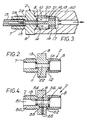
- reference numeral 40 indicates a handstock of a tyre pressure gauge (not shown) in which the reversible adaptor 2 and actuator probe 16 are mounted as described above with reference to Figures 1 and 2 and like reference numerals are used to indicate corresponding parts.
- the adaptor 2 is reversible to connect the gauge to either one of two valve sizes as desired and the probe 16 is arranged to open the valve in either fitted position of the adaptor 2 to admit the inflation gas to the gauge in similar manner to that described with reference to Figures 1 and 2 and will be understood by those skilled in the art without further description.
- the adaptor 2 comprises a tubular outer body 50 having a stepped through bore 51 and a tubular insert 52 slidably received in the bore 51.
- the opposed ends of the insert 52 are of different external diameter corresponding to the internal diameter of the spigots 7,8 forming an annular abutment shoulder 53 which seats against an annular abutment shoulder 54 formed at the junction of the spigots 7,8 to axially locate the insert 52 in the bore 51.
- the sealing rings 13,14 are secured, for example bonded, to the opposed ends of the insert 52 and the insert 52 is releasably secured in the bore 51 by a transverse grub screw 55 mounted in the collar 9 and engaging an annular groove 56 of V-shape formed in the outer surface of the insert 52.
- sealing rings 13,14 securing the sealing rings 13,14 to the insert 52 releasably secured in the adaptor bore 51 prevents accidental or inadvertent loss of the sealing rings 13,14 in service and facilitates replacement of one or both sealing rings 13,14 if required by simple removal and replacement of the insert 52.
- the adaptor 2 is reversible for connecting equipment to either one of two valve sizes as desired and retains an actuator probe for the valve as described previously herein.
- the outer body of the adaptor 2 has an elongated central portion and the insert 52 is of uniform diameter slidably received and retained in the wider end of the stepped bore 51 by grub screw 55 engaging groove 56.
- Sealing ring 14 is secured to one end of the insert 52 and sealing ring 13, separate from the insert 52, is seated against and retained between the abutment shoulder 53 within the bore 51 and the other end of the insert 52.
- both sealing rings 13 and 14 could be secured to the insert 52.
- the adaptor 2 is shown mounted with valve actuator probe 16 in a head 57 of the handstock 40 of a tyre pressure gauge.
- the head 57 has a main bore of stepped profile in which the probe 16 is retained by screwing one end of the adaptor 2 into the end of the bore.
- the probe shank 20 extends with radial clearance through the insert 52 to co-operate with a valve received in the outer end of the adaptor 2 and the probe head 18 has at least one through hole 19 for passage of the inflation medium as described previously herein.
- a pipe 58 Screwed into the head 57 at right angles to the main bore is a pipe 58 connected to the gauge by any suitable means indicated generally by reference numeral 59.
- the pipe 58 provides an extended reach and grip extending normal to longitudinal axis of the adaptor 2 for assisting the user in locating the adaptor 2 on the valve of a tyre (not shown), particularly where access to the valve is restricted for any reason.
- the spigots may be internally threaded for engagement with an externally threaded portion of the valve stem.
- any other suitable means may be used to provide a mechanical interlock between the adaptor and the valve stem.
- the spigots may be adapted for releasable connection to the equipment by any suitable means.
- valve actuator probe may be replaced by any suitable means for co-operating with the valve when received in either spigot.
- the analyser is not limited to the exemplary embodiment above-described.
- the reversible adaptor may be replaced by any other suitable means for connecting the analyser to a valve of a pneumatic tyre to be tested.
- the adaptor may be used to connected equipment to any pressurised body having a valve and is not limited to tyre valves as described in the exemplary embodiments.
Landscapes
- Engineering & Computer Science (AREA)
- Mechanical Engineering (AREA)
- Sampling And Sample Adjustment (AREA)
- Measuring Fluid Pressure (AREA)
Applications Claiming Priority (2)
| Application Number | Priority Date | Filing Date | Title |
|---|---|---|---|
| GB8811859 | 1988-05-18 | ||
| GB8811859A GB2218806B (en) | 1988-05-18 | 1988-05-18 | Device for testing pneumatic tyres |
Publications (2)
| Publication Number | Publication Date |
|---|---|
| EP0342909A2 true EP0342909A2 (fr) | 1989-11-23 |
| EP0342909A3 EP0342909A3 (fr) | 1990-10-24 |
Family
ID=10637167
Family Applications (1)
| Application Number | Title | Priority Date | Filing Date |
|---|---|---|---|
| EP19890304905 Withdrawn EP0342909A3 (fr) | 1988-05-18 | 1989-05-16 | Adaptateur renversable et analyseur de gaz pour pneus |
Country Status (3)
| Country | Link |
|---|---|
| US (2) | US4970904A (fr) |
| EP (1) | EP0342909A3 (fr) |
| GB (2) | GB2218806B (fr) |
Cited By (1)
| Publication number | Priority date | Publication date | Assignee | Title |
|---|---|---|---|---|
| KR200473709Y1 (ko) * | 2013-02-07 | 2014-07-24 | 한국환경공단 | 연소 가스 시료 채취용 플랜지 어댑터 |
Families Citing this family (13)
| Publication number | Priority date | Publication date | Assignee | Title |
|---|---|---|---|---|
| US5740835A (en) * | 1997-04-21 | 1998-04-21 | Tuthill Corporation | Valve connector |
| US6486771B1 (en) * | 1998-03-11 | 2002-11-26 | Fuller Brothers, Inc. | Tire inflation gas temperature, pressure, and oxygen monitoring system |
| DE60103895T2 (de) * | 2000-04-17 | 2005-07-07 | Newbow Aerospace Ltd., Park Farm North | Reifenprüfvorrichtung |
| US7591484B2 (en) | 2006-01-27 | 2009-09-22 | Cincinnati Test Systems, Inc. | Quick-connect fitting |
| US7478838B2 (en) * | 2006-01-27 | 2009-01-20 | Cincinnati Test Systems, Inc. | Quick-connect fitting |
| US7588048B2 (en) * | 2006-05-24 | 2009-09-15 | Ying-Che Huang | Air pump nozzle |
| WO2012075056A2 (fr) * | 2010-11-29 | 2012-06-07 | Saint-Gobain Performance Plastics Corporation | Articles présentant des micro-caractéristiques superficielles et leurs procédés de fabrication |
| CN103630429B (zh) * | 2013-12-04 | 2016-06-22 | 公安部天津消防研究所 | 一种基于近红外光谱分析的带压取样装置及取样方法 |
| US9347859B2 (en) * | 2013-12-12 | 2016-05-24 | Southwest Research Institute | Active fluid sampling from piston top land crevice of piston engine |
| US10508976B1 (en) | 2017-03-31 | 2019-12-17 | Advanced Micro Instruments, Inc. | Gas sampling device and method |
| JP6556196B2 (ja) | 2017-07-27 | 2019-08-07 | 倉敷化工株式会社 | アクティブ除振装置 |
| FR3074095B1 (fr) * | 2017-11-30 | 2020-12-11 | Ateq | Appareillage pour tester une fuite calibree de gaz sur une valve de pneumatique, bouchon pour un tel appareillage, et procede associe de controle de detection de fuite. |
| CN114992403B (zh) * | 2022-06-22 | 2023-11-14 | 青岛宏泰金属制品有限公司 | 一种高压自动防爆型新型铜管 |
Family Cites Families (8)
| Publication number | Priority date | Publication date | Assignee | Title |
|---|---|---|---|---|
| US1357153A (en) * | 1919-12-01 | 1920-10-26 | Dicken Ralph Chester | Compression-indicator |
| FR1147654A (fr) * | 1956-04-12 | 1957-11-28 | Raccord pour tubes | |
| FR1185495A (fr) * | 1957-10-24 | 1959-07-31 | Dispositif de détection et de contrôle de variations de composition d'un gaz, utilisable notamment comme prédétecteur d'incendie | |
| US3115033A (en) * | 1959-12-18 | 1963-12-24 | Kal Equip Company | Compression tester |
| US3786675A (en) * | 1970-11-23 | 1974-01-22 | Uson Corp | Portable gas leak detector |
| GB1599304A (en) * | 1977-09-23 | 1981-09-30 | Scovill Inc | Inflation valve connectors |
| US4345783A (en) * | 1980-06-09 | 1982-08-24 | Bergstrand Gunnar M | Pipe coupling device |
| US4914424A (en) * | 1987-03-02 | 1990-04-03 | Japan Storage Battery Company, Limited | Oxygen concentration monitor using galvanic cell type oxygen sensor |
-
1988
- 1988-05-18 GB GB8811859A patent/GB2218806B/en not_active Expired - Fee Related
-
1989
- 1989-05-16 EP EP19890304905 patent/EP0342909A3/fr not_active Withdrawn
- 1989-05-18 US US07/353,470 patent/US4970904A/en not_active Expired - Lifetime
-
1990
- 1990-09-06 US US07/578,245 patent/US5058418A/en not_active Expired - Fee Related
-
1991
- 1991-09-04 GB GB9118859A patent/GB2246860B/en not_active Expired - Fee Related
Cited By (1)
| Publication number | Priority date | Publication date | Assignee | Title |
|---|---|---|---|---|
| KR200473709Y1 (ko) * | 2013-02-07 | 2014-07-24 | 한국환경공단 | 연소 가스 시료 채취용 플랜지 어댑터 |
Also Published As
| Publication number | Publication date |
|---|---|
| GB2246860A (en) | 1992-02-12 |
| GB2218806A (en) | 1989-11-22 |
| US4970904A (en) | 1990-11-20 |
| EP0342909A3 (fr) | 1990-10-24 |
| US5058418A (en) | 1991-10-22 |
| GB9118859D0 (en) | 1991-10-23 |
| GB2246860B (en) | 1992-07-22 |
| GB2218806B (en) | 1992-07-22 |
| GB8811859D0 (en) | 1988-06-22 |
Similar Documents
| Publication | Publication Date | Title |
|---|---|---|
| US4970904A (en) | Reversible adaptor and gas analyzer for tires | |
| US4051803A (en) | Air leakage indicator device for a spare tire | |
| US6799455B1 (en) | Vehicle tire air monitor | |
| US4136560A (en) | Pressure gauge | |
| US7032611B1 (en) | Pressure regulator and method of use | |
| US3533063A (en) | Low pressure pneumatic tire transmitter | |
| US4373377A (en) | Universal tail pipe connector | |
| US4294110A (en) | Torque measuring system for an air tool | |
| US4901747A (en) | Tire inflation valve with pressure indicator | |
| US5665908A (en) | Manual tire deflating and pressure indicating device | |
| US5979232A (en) | Tire pressure indicator carried aboard a wheel | |
| US5557966A (en) | Cooling system pressure testing device for leak detection | |
| US4512278A (en) | Vehicle tire deflation signalling system | |
| US6588264B1 (en) | Pressure indicating devices | |
| EP0721403B1 (fr) | Valve de gonflage de pneus a indication de pression | |
| WO2001033054A2 (fr) | Adaptateur diagnostique destine a tester la pression d'un systeme de refroidissement | |
| WO2001016513A1 (fr) | Regulateur de pression et procede d'utilisation | |
| US3422836A (en) | Valve for dual chambered tires | |
| US2173619A (en) | Tire inflating and testing equipment | |
| US5771834A (en) | Double tire inflation balancer and tire pressure indicator | |
| US2742075A (en) | Tire and wheel construction | |
| US6418786B1 (en) | Aircheck safety valve | |
| EP3529088B1 (fr) | Indicateur visuel de débit de système de gonflage de pneu | |
| GB2087804A (en) | Apparatus for equalizing the pressures of pneumatic tyres | |
| GB2082734A (en) | A Valve and a Vehicle Tyre Deflation Signalling Means Incorporating the Valve |
Legal Events
| Date | Code | Title | Description |
|---|---|---|---|
| PUAI | Public reference made under article 153(3) epc to a published international application that has entered the european phase |
Free format text: ORIGINAL CODE: 0009012 |
|
| AK | Designated contracting states |
Kind code of ref document: A2 Designated state(s): AT BE CH DE ES FR GB GR IT LI LU NL SE |
|
| PUAL | Search report despatched |
Free format text: ORIGINAL CODE: 0009013 |
|
| AK | Designated contracting states |
Kind code of ref document: A3 Designated state(s): AT BE CH DE ES FR GB GR IT LI LU NL SE |
|
| STAA | Information on the status of an ep patent application or granted ep patent |
Free format text: STATUS: THE APPLICATION IS DEEMED TO BE WITHDRAWN |
|
| 18D | Application deemed to be withdrawn |
Effective date: 19910425 |