EP0342813B1 - Procédé et appareil pour la régénération capacitive de tissu et os - Google Patents
Procédé et appareil pour la régénération capacitive de tissu et os Download PDFInfo
- Publication number
- EP0342813B1 EP0342813B1 EP89304382A EP89304382A EP0342813B1 EP 0342813 B1 EP0342813 B1 EP 0342813B1 EP 89304382 A EP89304382 A EP 89304382A EP 89304382 A EP89304382 A EP 89304382A EP 0342813 B1 EP0342813 B1 EP 0342813B1
- Authority
- EP
- European Patent Office
- Prior art keywords
- resonator
- electrodes
- current
- patient
- series
- Prior art date
- Legal status (The legal status is an assumption and is not a legal conclusion. Google has not performed a legal analysis and makes no representation as to the accuracy of the status listed.)
- Expired - Lifetime
Links
Images


Classifications
-
- A—HUMAN NECESSITIES
- A61—MEDICAL OR VETERINARY SCIENCE; HYGIENE
- A61N—ELECTROTHERAPY; MAGNETOTHERAPY; RADIATION THERAPY; ULTRASOUND THERAPY
- A61N1/00—Electrotherapy; Circuits therefor
- A61N1/40—Applying electric fields by inductive or capacitive coupling ; Applying radio-frequency signals
-
- Y—GENERAL TAGGING OF NEW TECHNOLOGICAL DEVELOPMENTS; GENERAL TAGGING OF CROSS-SECTIONAL TECHNOLOGIES SPANNING OVER SEVERAL SECTIONS OF THE IPC; TECHNICAL SUBJECTS COVERED BY FORMER USPC CROSS-REFERENCE ART COLLECTIONS [XRACs] AND DIGESTS
- Y10—TECHNICAL SUBJECTS COVERED BY FORMER USPC
- Y10S—TECHNICAL SUBJECTS COVERED BY FORMER USPC CROSS-REFERENCE ART COLLECTIONS [XRACs] AND DIGESTS
- Y10S128/00—Surgery
- Y10S128/901—Suppression of noise in electric signal
Definitions
- This invention relates generally to the electric stimulation of tissue and bone and, more particularly, to the production of a stimulative electric current in the tissue or bone via a capacitively established electric field.
- auxiliary stimulating current is induced offers several alternative forms of classification.
- Invasive techniques involve the application of electric current directly to the site of the trauma or fracture through electrodes implanted at the site. While this approach minimizes the electric potential required to generate a particular desired current in the tissue or bone, it also involves the expense and risk of infection attendant surgical implantation procedures. As a result, noninvasive procedures, in which the flow of electric current in the tissue or bone is induced by apparatus external to the patient, are preferred.
- the noninvasive establishment of an AC current in tissue or bone can be further grouped according to the electric principle involved in its production.
- a resistive approach involves the conduction of current directly to the patient through special electrodes coupled to the patient's skin via conductive gel. This technique has the disadvantage of requiring good electrical contact between the electrodes and the skin, necessitating the periodic replacement of the conductive gel on the electrodes.
- a second, or inductive, approach employs magnetic fields to establish the desired AC current in the tissue or bone.
- this approach involves the application of an electric current to magnetic coils positioned proximate the patient. The flow of current through the coils produces a magnetic field in the patient's bone or tissue, resulting in the establishment of the desired alternating therapeutic current.
- This approach has a number of disadvantages including the required use of bulky magnetic coils and an energy source having an output whose frequency and waveform are sufficient to induce the desired stimulating currents at the patient site.
- the inductive approach also involves relatively large energy losses attributable to the heating of the coil windings produced by the flow of current therethrough.
- the third technique for noninvasively establishing an alternating current in the patient's tissue or bone can be referred to as the "capacitive" or electric field approach.
- This technique typically employs a pair of electrodes that are placed on opposite sides of the treatment site and are insulated from the patient's skin. Energy applied to the electrodes establishes an electric field between the electrodes, normal to the skin. It is this electric field that induces the alternating therapeutic current at the treatment site.
- the capacitive production of therapeutically effective levels of electric current at the patient treatment site traditionally presents several additional problems.
- the patient's skin normally contributes a series capacitive reactance to the equivalent electric circuit representative of the elements between the electrodes.
- a much larger variable capacitive reactance is exhibited by the insulative, dielectric "gaps" between the electrodes and the patient.
- the peak energy stored electrostatically in both the electrode-to-skin interface and the epidermis during one cycle of the alternating voltage potential applied to the electrodes is substantially larger than the energy absorbed by the tissue and bone being treated.
- This stored energy is typically either dissipated within the source or radiated as electromagnetic energy, resulting in a system inefficiency or energy loss. As a result, high levels of reactive power are required to establish the desired therapeutic current.
- an inductive reactance can be employed to produce a resonant circuit that reduces the energy losses.
- a series-connected inductor can be used to recapture the stored energy and apply it to the treatment site during the next cycle of the alternating voltage applied to the electrodes. As a result, only a relatively small amount of energy is dissipated and radiated.
- the capacitive technique of establishing therapeutic current in tissue and bone still presents several problems.
- the capacitive reactance exhibited by the dielectric gaps between the electrodes and the patient represents a rather large and variable electrical impedance to the drive circuit.
- the addition of the inductor to form a resonant circuit having a high quality factor Q provides a significant reduction in impedance when the circuit is operated at its resonant frequency.
- the capacitive portion of the circuit may vary substantially in response to both the condition of the patient and movement between the electrodes and patient, when a fixed inductance is employed the circuit can be maintained at resonance only by adjusting the frequency of the driver to correspond to the resonant frequency of the circuit as it varies with the changing capacitance.
- a variable inductive reactance can be used to negate the effect of the changes in capacitance, leaving the resonant frequency of the circuit unchanged.
- an apparatus for applying an electric current to a region of a patient through a pair of electrodes 14 positionable in non-contacting relationship with respect to the patient, the region of the patient and any gaps between the patient and the electrodes exhibiting a series of capacitance C1 and resistance R1 said apparatus being self oscillatory and comprising: inductive means L1, coupled to one of the electrodes 14, for defining a resonator 32 in cooperation with the series capacitance C1 and resistance R2; oscillation means 16, coupled to said inductive means L1, for providing to said resonator 32 a periodic current whose frequency is substantially equal to the resonant frequency of said resonator 32 and means C2 for limiting the occurrence of spurious frequencies in said periodic current provided by said oscillation means 16.
- the method comprising the steps of connecting the electrodes to a self oscillatory circuit, the self oscillatory circuit being provided by: providing inductive means L1 coupled to one of the electrodes for defining a resonator 32 in cooperation with the series capacitance C1 and resistance R2, providing to said resonator 32 a periodic current whose frequency is substantially equal to the resonant frequency of said resonator and limiting the occurrence of spurious oscillation frequencies in said periodic current provided to said resonator.
- FIGURE 1 a system 10 for facilitating the healing of traumatized tissue and broken or fractured bone is illustrated.
- the system 10 establishes an alternating electric current at a treatment site 12, which includes the bone and tissue for which enhanced regeneration is desired. As discussed in greater detail below, this therapeutic current is induced by the establishment of an electric field between a pair of electrodes 14 positioned on opposite sides of the site 12.
- a free-running oscillator 16, included in a control and output subsystem 18, provides the energy required to maintain the field between electrodes 14.
- Oscillator 16 is powered by a supply 20 and is controllably activated and deactivated in response to a timer 22.
- a visual display 24, included in subsystem 18, provides an output indicating that a therapeutic current is flowing at the treatment site 12.
- subsystem 18 includes a timing pulse counter 26 to provide information concerning the length of time during which therapeutic current is applied to the site 12 and an alarm 28 that indicates that supply 20 is no longer able to sustain the desired operation of oscillator 16.
- system 10 While the operation of system 10 is described in greater detail below, its primary function is to establish a therapeutic current at site 12. In the preferred arrangement, an alternating therapeutic current of approximately 5 milliamperes is produced. The frequency of the alternating current is a function of a variety of factors, including the structure of site 12, electrodes 14, and free-running oscillator 16, as well as the relative position of site 12 and electrodes 14.
- the current's frequency should be sufficiently high to prevent the deleterious electromigration of isotopes or ionic species at the treatment site 12.
- the frequency must be sufficiently low to ensure that current is induced, for example, in the fracture of a bone lying well beneath the surface of the patient's skin.
- electrodes 14 are constructed to satisfy a variety of operating criteria. For example, because the current-inducing electric field is established normal to the surface of electrodes 14, the area of electrodes 14 directly affects the cross-sectional area of the treatment site 12 in which a therapeutic current is produced. In addition, the construction details of electrodes 14, including their size and the materials employed, will influence the capacitive reactance introduced by the electrodes. In the preferred arrangement, electrodes 14 are circular plates of conductive elastomer, such as carbon-filled silicone rubber, having a diameter of 8 cm, a thickness of 0.1 cm, and a typical capacitance of 50 pF.
- conductive elastomer such as carbon-filled silicone rubber
- the electrodes 14 are preferably spaced apart from the treatment site 12 by gaps 30.
- the gaps 30 can be physically maintained by the inclusion of a rigid dielectric material between the electrodes 14 and site 12.
- the electrodes 14 are embedded in a cast that surrounds the traumatized tissue and broken or fractured bones.
- the gaps 30 then include both the dielectric cast material and any air gap interposed between electrodes 14 and the treatment site 12 of the patient. Because the length of the air gaps will likely vary substantially in response to, for example, patient movement, the equivalent capacitive reactance of the circuit may undergo significant variations. It is these variations that the free-running oscillator 16 is designed to compensate for, resulting in the production of an acceptable therapeutic current at the site 12 under all normally expected conditions.
- the oscillator 16 operates in connection with a series resonant circuit or resonator 32 defined by an equivalent site circuit 34 and an inductor L1.
- the equivalent circuit 34 includes a resistive component R1 and a capacitive component C1 that are representative of site 12, electrodes 14, and gaps 30.
- the oscillator 16 is constructed to ensure that its operating frequency precisely tracks the changing resonant frequency of resonator 32.
- Oscillator 16 is further constructed from a minimum of components, providing a stable level of injected current over a desired frequency range without the introduction of high-frequency spurious oscillations.
- free-running oscillator 16 is designed to operate resonator 32 at its resonant frequency.
- Resonance is, by definition, the condition in which the impedance of the resonator 32 is purely resistive, causing the voltage and current at the input of resonator 32 to be in phase. Because the inductive and capacitive components L1 and C1 do not affect the current flowing through resonator 32 in this condition, the magnitude of the current is a function only of the voltage applied to resonator 32 and the resistance of resonator 32.
- the circuit shown in FIGURE 2 can be considered to include a forward network 38 and a feedback network 40.
- the forward network 38 includes an amplifier 42 that amplifies the output V1 of feedback network 40 by a complex, frequency-dependent gain A to produce an output voltage V0.
- the feedback network 40 includes the resonator 32 and feedback elements 46.
- the feedback network 40 is characterized by a complex, frequency-dependent transfer function ⁇ and produces the output V1, which is equal to the product of voltage V0 and the transfer function ⁇ .
- the loop gain of the circuit in FIGURE 2 is equal to the product of the terms A and ⁇ . As this loop gain approaches +1, the ratio of the circuit's output voltage to its input voltage approaches infinity, allowing the circuit to oscillate or produce an output even when no input is applied. Both A and ⁇ are comples, frequency-dependent quantities that can be expressed in polar form as an amplitude and an angle. Because oscillation can take place only if the vector product of A and ⁇ is +1, the product of the amplitudes of A and ⁇ must be equal to +1, while the sum of the angles of A and ⁇ must equal 0. This latter characteristic defines the second requirement for oscillation, which is that the loop phase shift must be equal to 0 or some multiple of 360 degrees.
- resonator 32 can be considered to include four elements.
- the equivalent circuit 34 representative of site 12, electrodes 14, and gaps 30, includes a series capacitance C1 and resistance R1.
- the portion of C1 attributable to the gaps 30 is relatively large and variable, leading to fluctuations in the resonant frequency of resonator 32.
- the equivalent series resistance R1 includes the resistance inherent in the living tissue, which is on the order of 100 ohms.
- This resistance R1 also includes the effective series resistance associated with the forward network 38 and feedback network 40, as well as the losses in the series inductor L1. This latter component may be made relatively small by carefully designing the inductor L1 to provide a high quality factor Q.
- resonator 32 also includes a capacitor C2 connected in series with equivalent circuit 32.
- Capacitor C2 prevents oscillator 16 from operating in spurious and multiple high-frequency modes by introducing a high-frequency roll-off into the feedback network 42.
- the capacitance (e.g., 10 nF) of capacitor C2 is typically much greater than that of C1.
- One end of capacitor C2 is coupled to ground, while the other end is connected directly to equivalent circuit 34 and by feedback to the forward network 38.
- the series inductor L1 is included in resonator 32 to reduce the dissipation of energy from the electric field established between electrodes 14 by receiving most of the stored energy of the field and returning it during the next cycle of the alternating potential applied to the electrodes 14.
- Inductor L1 typically has an inductance on the order of 100 mH.
- network 40 preferably includes a source 42 that provides a low-impedance output voltage to resonator 32.
- the voltage source 42 also preferably operates in a switching mode for enhanced efficiency.
- a suitable source or amplifier 42 is a complementary, metal-oxide-semiconductor inverter of the type manufactured by Motorola under the designations MC14049UB or MC14069UB. Such an amplifier 42 provides a square wave output and introduces a phase shift of approximately 180 degrees into the loop at the desired operating frequency of around 50 kilohertz.
- Forward network 40 also includes a resistor R2.
- the capacitive and inductive reactances have a cancellative effect on each other, exerting no influence on the amplitude of the current flowing through resonator 32.
- the therapeutic current induced at the patient site 12 can be controlled either by altering the voltage applied to resonant circuit 32 or its series resistance.
- the resistor R2 is connected in series with the equivalent resistance R1 of resonator 32 to regulate the therapeutic current to the desired level.
- R2 has a resistance (e.g., 750 ohms) that is sufficient to increase the total series resistance of the circuit to approximately 1000 ohms.
- an oscillator output of approximately 5 volts rms is achieved, providing a normally desired therapeutic current of 5 milliamperes at resonance.
- feedback network 40 includes both the resonator 32 and feedback elements 46.
- Feedback elements 46 provide the loop with the desired unity gain and zero phase shift characteristics. While elements 46 could be merged with the forward network 38, both in theory and in practice, they are shown separately in FIGURE 2 to assist in an understanding of the circuit.
- the feedback elements 46 include an amplifier 48 and phase lag 50, which ensure that the complex transfer function ⁇ of the feedback network 40 satisfies the loop's unity gain and zero phase shift requirements.
- the gain provided by amplifier 48 compensates for both the gain of amplifer 42 and the attenuation introduced by resonator 32.
- phase shift the current flowing through the resonator 32 is in phase with the voltage at the output of the forward network 38 at resonance. This current produces a voltage across capacitor C2 having a phase that lags that of the output voltage from amplifier 42 by 90 degrees.
- phase lag 50 is required to provide the remaining 90 degrees of shift. As a result, 360 degrees of phase shift is produced, allowing stable oscillation.
- the combined gain of amplifiers 42 and 48 is designed to exceed any voltage attenuation introduced by the resonator 32 and phase shifter 50.
- the unity gain condition for stable oscillation of the loop is satisfied by making at least one of the amplifiers 42 or 48 saturable. With a 4049-type device employed for amplifer 42, such saturation is inherent.
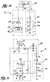
- FIGURE 3 illustrates, in slightly greater detail, a preferred embodiment of the system 10 of FIGURE 2.
- the capacitor C1 of FIGURE 2 has been depicted as two capacitors C1 a and C1 b in FIGURE 3.
- the capacitance of element C1 a corresponds to that of the electrodes 14 and gaps 30, while capacitor C1 b is representative of site 12.
- the series resonant circuit 32 of FIGURE 3 also includes an additional capacitor C3, having a capacitance on the order of 220 picofarads. While the inclusion of this capacitor C3 is not essential, it assures oscillation of system 10, regardless of the normal variation of capacitance of elements C1 a and C1 b . As will be appreciated, the series capacitance of elements C1 a and C1 b may become very large and even representative of a virtual short circuit when, for example, the patient is perspiring heavily and the electrodes 14 are spaced apart from the patient by only a woven cotton sleeve designed to "wick" perspiration from the site.
- the resonant frequency of resonator 32 could shift sufficiently to prevent oscillator 16 from achieving a unity loop gain or zero phase shift and, hence, oscillation.
- the resonant frequency of resonator 32 cannot drop to less than approximately one-half its nominal value and oscillation is assured. It is also preferable to use the additional capacitor C3 to prevent the possible flow of direct current through the electrode circuit. Such flow might have adverse consequences through electrolytic action, especially in the presence of moisture on the electrodes.
- FIGURE 3 also includes additional details regarding the construction of the feedback elements 46.
- this portion of network 42 is designed to satisfy the zero phase shift and unity gain requirements of oscillation by introducing a 90-degree phase lag into the circuit, as well as sufficient gain to overcome the loss introduced by the resonator 32. Both functions are conveniently provided by an operational amplifier 52 connected "open-loop" or without feedback.
- the operational amplifier 52 should have a sufficient open-loop gain over the range of expected operating frequencies to make the oscillator loop gain equal to unity without depending upon amplifier 42 for gain.
- a suitable operational amplifier 52 is provided by any one of the four operational amplifiers included in the integrated circuit device manufactured by Texas Instruments under the part designation TLC27M4. This device is available with internal compensation to provide a 90-degree phase shift over a wide frequency range, including the desired operating frequency of approximately 50 kilohertz.
- the inverting input of the operational amplifier 52 is coupled to a voltage divider formed by the series combination of resistors R3 and R4. More particularly, one end of resistor R3 is coupled to the supply 20, one end of resistor R4 is coupled to ground, and the connection of resistors R3 and R4 have a resistance that is on the inverting input. Because both resistors R3 and R4 is coupled to the order of 100 kilohms, a voltage equal to approximately one half the supply 20 voltage V dd is applied to the inverting input.
- the inverting input of operational amplifier 52 is also coupled to ground by a bypass capacitor C4 having a capacitance of 100 nF and the noninverting input is coupled to the resonator 32 at the ungrounded side of capacitor C2.
- Resistor R5 is coupled between the noninverting input of operational amplifier 52 and the output of the amplifier 42 in forward network 38, as shown in FIGURE 3.
- Resistor R5 has a resistance of approximately 100 kilohms and is included to ensure the initiation of oscillation by placing amplifiers 42 and 52 within their common-mode ranges at start-up.
- the forward network 38 preferably employs a complementary metal-oxide-semiconductor inverter for amplifier 42.
- the amplifier is driven rail-to-rail at the voltage V dd provided by supply 20 to enhance efficiency and is also coupled to a bypass capacitor C5 having a capacitance of approximately 100 nF.
- resistor R2 is included in the forward network 38 and has a resistance that is sufficient to provide the desired therapeutic current level for the particular output produced by amplifier 42.
- a pair of reverse, parallel-connected light-emitting diodes D1 and D2, such as those manufactured by Texas Instruments under the part number TIL213-2 are included in series with resistor R2.
- the diodes D1 and D2 output an easily observable quantity of light when energized at the therapeutic current level of approximately 5 milliamperes rms.
- the light-emitting diodes D1 and D2 directly indicate the application of therapeutically effective current to the site 12, rather than simply indicating that circuit power is available to establish such a current. This advantageously avoids the production of an output if oscillation ceases due to the failure of a component or an improper spacing of the electrodes 14.
- each light-emitting diode D1 and D2 only passes current in one direction, the reverse, parallel connection of diodes D1 and D2 is employed to accommodate the alternating current established in the resonant circuit 32.
- the forward drop of diodes D1 and D2 is on the order of one volt. As a result, the effective voltage applied to resonator 32 is reduced, requiring that the resistive value of resistor R1 be adjusted accordingly to maintain the desired level of therapeutic current.
- the active operational amplifier 52 can be removed from the circuit and a resistor R6 and capacitor C6 employed as the feedback elements 46.
- capacitor C2 exhibiting a high reactance, for example, at a capacitance of 1 nanofarad, the voltage across capacitor C2 will remain relatively high.
- resistor R6 and capacitor C6 also produces the desired phase shift of approximately 90 degrees for all frequencies that are attenuated by roughly a tenfold factor or more.
- amplifier 42 Another modification relates to the use of amplifier 42. While a single amplifier 42 is shown in the schematic diagram of FIGURE 3, a number of such elements are normally connected in parallel to achieve an internal series resistance that is relatively low in comparison to that of R2. As will be appreciated, the amplifier resistance is heavily dependent upon ambient temperature and varies from unit to unit in a production run. Because the series resistance of the circuit directly affects current level, the resistance of resistor R2 should always be dominant if the therapeutic current level is to be accurately maintained.
- a 9-volt battery may conveniently be employed for power supply 20.
- the use of such a battery not only ensures the absence of any high-voltage failure modes, it also contributes to the relative portability of system 10, which may be particularly desirable when system 10 is mounted to a patient's cast for extended periods of use.
- a power supply voltage output 28 is included to provide an output indicative of the status of supply 20.
- a simple direct current voltmeter could be employed for output 28 in indicate the voltage available from supply 20.
- output 28 could include a comparator having the battery voltage as one input, a threshold voltage as another input, and an output coupled to an audible or visual alarm when the battery voltage drops below the threshold.
- Subsystem 18 also includes a timer 22 designed to sequence oscillator 16 on and off at desired intervals. More particularly, with empirical studies conducted to determine the cycling rate resulting in the production of an optimal therapeutic effect, timer 22 can then be set to cycle oscillator 16 on and off at that rate. In addition, timer 22 can be set to initiate and interrupt this cycled operation at desired times.
- timer 22 various constructions can be employed for timer 22, depending on the particular operation desired. For example, if an adjustable start time, stop time, and cycle rate are desired, along with the ability to retain output information regarding the treatment period, a microprocessor-based timer 22 programmed with an appropriate set of operating instruction may be useful. In this manner, a timing pulse output 26 can easily be provided, displaying information indicative of the number of timing pulses applied to oscillator 16, for analysis by the physician. Alternatively, output 26 can be a simple counter.
- the visual display 24 preferably includes a pair of reverse, parallel-connected, light-emitting diodes D1 and D2, which directly indicate the establishment of a therapeutic current at the site 12.
- diodes D1 and D2 will appear to be lit and extinguished for corresponding intervals.
- the cycle rate produced by timer 22 can be altered to provide a change in the display produced by diodes D1 and D2 indicating a low-battery conditon.
- the system 10 constructed in the manner described above has a number of advantages.
- the system 10 induces the desired therapeutic current at the patient site 12 in a straightforward manner with relatively few components.
- the system 10 is also stable, rejects high frequency spurious oscillations, and produces an output directly indicating the establishment of a therapeutic current at the treatment site 12.
- Another advantage of system 10 is that it enhances patient safety by avoiding the application of a high-voltage drive output directly to the electrodes 14. More particularly, with a constant drive voltage employed, the current established at the treatment site 12 varies in inverse proportion to the capacitive reactance of the equivalent circuit 34. In certain circumstances, for example, when electrodes 14 come into direct contact with the skin of a heavily perspiring patient, the capacitive reactance may be negligible, resulting in the production of a large and potentially injurious "fault" current.
- the disclosed system 10 overcomes this difficulty by providing a drive voltage that is limited, in case of direct electrode-to-skin contact, to the relatively low voltage V dd of the supply 20, for example, 9 volts. As a result, system 10 has no high-voltage failure modes. Further, the drive current is limited by resistor R2, which may be a series of several resistors or a single resistor constructed to have only an open-circuit failure mode. In no circumstance will any failure of an active component result in an over-current condition hazardous to the patient.
Landscapes
- Health & Medical Sciences (AREA)
- Animal Behavior & Ethology (AREA)
- Biomedical Technology (AREA)
- Nuclear Medicine, Radiotherapy & Molecular Imaging (AREA)
- Radiology & Medical Imaging (AREA)
- Life Sciences & Earth Sciences (AREA)
- Engineering & Computer Science (AREA)
- General Health & Medical Sciences (AREA)
- Public Health (AREA)
- Veterinary Medicine (AREA)
- Electrotherapy Devices (AREA)
- Oscillators With Electromechanical Resonators (AREA)
- Semiconductor Integrated Circuits (AREA)
Claims (18)
- Appareil pour l'application d'un courant électrique à une région d'un patient au travers d'une paire d'électrodes (14), pouvant être positionnées l'une par rapport à l'autre sans contact avec le patient, la région du patient et tous intervalles entre le patient et les électrodes présentant une capacitance C1 et une résistance R1 série, ledit appareil étant auto oscillatoire et comprenant :
des moyens inductifs L1, couplés à l'une des électrodes (14), pour définir un résonateur (32) en coopération avec la résistance R2 et la capacitance C1 série ;
des moyens d'oscillation (16) couplés auxdits moyens inductifs L1 pour fournir audit résonateur (32) un courant périodique dont la fréquence est sensiblement égale à la fréquence de résonance dudit résonateur (32) ; et
des moyens C2 pour limiter l'apparition de fréquences parasites dans ledit courant périodique fourni par lesdits moyens (16) d'oscillation. - Appareil selon la revendication 1, dans lequel lesdits moyens d'oscillation (16) définissent une boucle fermée avec ledit résonateur (32) et comprennent en outre une première section (38) pour fournir un premier ajustement d'amplitude et un premier écart de phase dans les signaux conduits par ladite boucle, et une seconde section (40) pour fournir un second ajustement d'amplitude et un second écart de phase pour les signaux conduits par ladite boucle, ladite boucle fermée ayant un gain d'une unité et un écart de phase équivalent de zéro degré.
- Appareil selon la revendication 2, dans lequel lesdits moyens C2 pour limiter l'apparition de fréquences oscillatoires parasites est un élément capacitif C2 définissant en outre ledit résonateur (32) en coopération avec lesdits moyens inductifs L1 et ladite capacitance C1 et résistance R1 série, ledit élément capacitif C2 introduisant un écart de phase d'environ 90° à l'intérieur de ladite boucle.
- Appareil selon la revendication 3, dans lequel ladite première section (38) comprend un inverseur complémentaire (42) métal-oxyde-semi-conducteur, ledit premier écart de phase étant approximativement égal à 180°.
- Appareil selon la revendication 4, dans lequel ladite section (40) comprend un amplificateur opérational (52), ledit second écart de phase étant approximativement égal à 90°.
- Appareil selon la revendication 5, comprenant en outre des moyens R2 résistifs de commande de courant, couplés audit résonateur (32), pour commander l'amplitude dudit courant périodique fourni audit résonateur.
- Appareil selon la revendication 6, comprenant en outre des moyens de sortie visuels (24) pour produire une sortie visuelle indicatrice de la fourniture dudit courant périodique audit résonateur (32).
- Appareil selon la revendication 7, dans lequel lesdits moyens de sortie visuels (24) comprennent une paire de diodes inversées D1, D2, émettrices de lumière, reliées en parallèle, couplées en série avec ledit résonateur (32).
- Appareil selon la revendication 1, comprenant en outre des moyens pour refermer lesdits moyens d'oscillation (16) entre les périodes durant lesquelles ledit courant du résonateur est fourni et n'est fourni.
- Appareil selon la revendication 9, comprenant en outre des moyens (26) pour produire un signal de sortie indiquant le nombre de périodes desdits moyens d'oscillation (16) qui ont été refermées.
- Appareil selon la revendication 1, dans lequel l'actionnement desdits moyens d'oscillation (16) peuvent être commandés par une source de tension (20), ledit appareil comprenant en outre des moyens (28) pour indiquer si la tension disponible à la source (20) a chuté en dessous d'un niveau donné prédéterminé.
- Appareil selon la revendication 1, comprenant en outre des moyens visuels de sortie (24) pour fournir une sortie visuelle indiquant la fourniture dudit courant périodique audit résonateur (32).
- Appareil selon la revendication 12, dans lequel lesdits moyens visuels (24) comprennent une paire de diodes inversées D1, D2, émettrices de lumière, reliées en parallèle, couplées en série avec ledit résonateur.
- Appareil selon la revendication 1, dans lequel l'actionnement desdits moyens d'oscillation (16) peut être commandé par une source de tension (20), ledit appareil comprenant en outre des moyens de sortie (24) pour fournir un premier signal de sortie indiquant la fourniture dudit courant périodique audit résonateur (32) lorsque la tension disponible à la source (20) se situe au-dessus d'un niveau prédéterminé et un second signal de sortie lorsque la tension disponible à la source (20) est située en-dessous du niveau prédéterminé.
- Appareil selon l'une quelconque des revendications précédentes, dans lequel la source (16) de tension à basse impédance peut être actionnée de façon à appliquer, à l'une des électrodes (14), une onde de sortie carrée, décalée en phase d'environ 180° par rapport à une source d'entrée.
- Appareil selon l'une quelconque des revendications précédentes, dans lequel le champ électrique établi présente une fréquence et une amplitude stables.
- Procédé pour appliquer un courant électrique à une région d'un patient à travers une paire d'électrodes (14), pouvant être positionnées en relation par rapport au patient sans contact avec lui, la région du patient et tous intervalles entre le patient et les électrodes (14) présentant une résistance R1 et une capacitance C1 série, le procédé comprenant les étapes consistant à relier les électrodes à un circuit auto oscillatoire, le circuit auto oscillatoire étant constitué de la façon suivante :
on couple dos moyens inductifs L1 à l'une des électrodes de façon à définir un résonateur (32) en coopération avec la résistance R2 et la capacitance C1 série ;
on fournit audit résonateur (32) un courant périodique dont la fréquence est sensiblement égale à la fréquence de résonance dudit résonateur (32) ; et
on limite l'apparition de fréquences oscillatoires parasites dans ledit courant périodique fourni audit résonateur (32). - Procédé selon la revendication 17, comprenant en outre l'étape consistant à produire un signal de sortie lorsque ledit courant périodique est fourni audit résonateur (32).
Applications Claiming Priority (2)
| Application Number | Priority Date | Filing Date | Title |
|---|---|---|---|
| US07/188,337 US5038780A (en) | 1988-04-29 | 1988-04-29 | Method and apparatus for capacitively regenerating tissue and bone |
| US188337 | 2005-07-25 |
Publications (3)
| Publication Number | Publication Date |
|---|---|
| EP0342813A2 EP0342813A2 (fr) | 1989-11-23 |
| EP0342813A3 EP0342813A3 (fr) | 1992-02-12 |
| EP0342813B1 true EP0342813B1 (fr) | 1996-04-10 |
Family
ID=22692744
Family Applications (1)
| Application Number | Title | Priority Date | Filing Date |
|---|---|---|---|
| EP89304382A Expired - Lifetime EP0342813B1 (fr) | 1988-04-29 | 1989-05-02 | Procédé et appareil pour la régénération capacitive de tissu et os |
Country Status (4)
| Country | Link |
|---|---|
| US (2) | US5038780A (fr) |
| EP (1) | EP0342813B1 (fr) |
| AT (1) | ATE136473T1 (fr) |
| DE (1) | DE68926179T2 (fr) |
Families Citing this family (28)
| Publication number | Priority date | Publication date | Assignee | Title |
|---|---|---|---|---|
| US5267939A (en) * | 1989-01-09 | 1993-12-07 | Life Resonances, Inc. | Techniques for controlling osteoporosis using non-invasive magnetic fields |
| JP2598568B2 (ja) * | 1990-11-20 | 1997-04-09 | オリンパス光学工業株式会社 | 電子内視鏡装置 |
| US5565005A (en) * | 1992-02-20 | 1996-10-15 | Amei Technologies Inc. | Implantable growth tissue stimulator and method operation |
| DE69228531T2 (de) * | 1992-02-20 | 1999-07-29 | Neomedics Inc | Implantierbarer Knochenwachstumsstimulator |
| JP3526587B2 (ja) * | 1992-11-12 | 2004-05-17 | 昇 堀口 | 生命体の治癒力向上装置 |
| US5524624A (en) * | 1994-05-05 | 1996-06-11 | Amei Technologies Inc. | Apparatus and method for stimulating tissue growth with ultrasound |
| FR2726477B1 (fr) * | 1994-11-04 | 1996-12-27 | Patois Raymond | Resonateur-emetteur d'ondes electromagnetiques h.f. a effets therapeutiques renforces |
| US7452358B2 (en) | 1996-01-05 | 2008-11-18 | Thermage, Inc. | RF electrode assembly for handpiece |
| US7473251B2 (en) | 1996-01-05 | 2009-01-06 | Thermage, Inc. | Methods for creating tissue effect utilizing electromagnetic energy and a reverse thermal gradient |
| US7229436B2 (en) | 1996-01-05 | 2007-06-12 | Thermage, Inc. | Method and kit for treatment of tissue |
| US20030212393A1 (en) | 1996-01-05 | 2003-11-13 | Knowlton Edward W. | Handpiece with RF electrode and non-volatile memory |
| DE69941557D1 (de) * | 1998-01-15 | 2009-12-03 | Regenesis Biomedical Inc | Verbesserte vorrichtung zur behandlung mittels pulsierter elektromagnetischer energie |
| AU763938B2 (en) * | 1998-09-11 | 2003-08-07 | Gr Intellectual Reserve, Llc | Methods for using resonant acoustic energy to detect or effect structures |
| US6061597A (en) * | 1998-12-18 | 2000-05-09 | Robert D. Rieman | Method and device for healing bone fractures |
| US7177696B1 (en) | 1999-06-09 | 2007-02-13 | H & P Medical Research, Inc. | Multiple selectable field/current-voltage pads having individually powered and controlled cells |
| WO2002006234A1 (fr) * | 2000-07-17 | 2002-01-24 | Takeda Chemical Industries, Ltd. | Derives de sulfonate, procede de production et utilisation de ces derives |
| US7010353B2 (en) * | 2002-01-07 | 2006-03-07 | Ebi, L.P. | Non-invasive capacitively coupled electrical stimulation device for treatment of soft tissue wounds |
| GB2406519B (en) | 2003-09-30 | 2007-04-25 | David John Chapman-Jones | Dressing for tissue treatment |
| US8082038B2 (en) * | 2004-07-09 | 2011-12-20 | Ebi, Llc | Method for treating degenerative disc disease using noninvasive capacitively coupled electrical stimulation device |
| US7486993B2 (en) * | 2004-08-05 | 2009-02-03 | Neurotone Systems, Inc. | Brain stimulation method and device |
| US9215788B2 (en) * | 2005-01-18 | 2015-12-15 | Alma Lasers Ltd. | System and method for treating biological tissue with a plasma gas discharge |
| CA2526671C (fr) * | 2005-01-18 | 2015-08-11 | Msq Ltd. | Systeme et methode ameliores de chauffage des tissus biologiques au moyen d'energie rf |
| AT505042B1 (de) * | 2007-03-21 | 2009-11-15 | Med El Elektromed Geraete Gmbh | System zur elektrostimulation |
| FR2929450B1 (fr) * | 2008-03-28 | 2010-08-20 | Seb Sa | Appareil electromenager comportant une pompe piezo-electrique munie d'un circuit d'alimentation electrique simplifie |
| AU2009295227B2 (en) * | 2008-09-19 | 2015-07-16 | Terry William Burton Moore | A method and device for reducing muscle tension through electrical manipulation |
| WO2010054080A1 (fr) | 2008-11-05 | 2010-05-14 | Fmc Technologies, Inc. | Coalesceur electrostatique a gaz |
| CN109173054B (zh) * | 2018-10-17 | 2023-11-03 | 丁毅 | 一种电位治疗仪 |
| EP4288138A1 (fr) | 2021-02-05 | 2023-12-13 | Theragen, Inc. | Systèmes, méthodes et dispositifs de thérapie par stimulation électrique |
Family Cites Families (26)
| Publication number | Priority date | Publication date | Assignee | Title |
|---|---|---|---|---|
| US3368565A (en) * | 1965-04-02 | 1968-02-13 | Dynapower Systems Corp Of Cali | Electrotherapeutic treatment head with tuning means |
| US3457924A (en) * | 1966-07-21 | 1969-07-29 | Dynapower Systems Corp Of Cali | Body load sensitive electrotherapeutic equipment |
| US3566877A (en) * | 1968-01-05 | 1971-03-02 | Luther B Smith | Electrotherapeutic apparatus and treatment head and method for tuning said treatment head |
| US3785383A (en) * | 1971-03-29 | 1974-01-15 | Anglemyer A | Electrostatic wand |
| US3893462A (en) * | 1972-01-28 | 1975-07-08 | Esb Inc | Bioelectrochemical regenerator and stimulator devices and methods for applying electrical energy to cells and/or tissue in a living body |
| DE2314573C2 (de) * | 1973-03-23 | 1986-12-18 | Werner Dipl.-Ing. 8000 München Kraus | Gerät zur Förderung von Heilungsprozessen |
| US4105017A (en) * | 1976-11-17 | 1978-08-08 | Electro-Biology, Inc. | Modification of the growth repair and maintenance behavior of living tissue and cells by a specific and selective change in electrical environment |
| US4315503A (en) * | 1976-11-17 | 1982-02-16 | Electro-Biology, Inc. | Modification of the growth, repair and maintenance behavior of living tissues and cells by a specific and selective change in electrical environment |
| US4266532A (en) * | 1976-11-17 | 1981-05-12 | Electro-Biology, Inc. | Modification of the growth, repair and maintenance behavior of living tissues and cells by a specific and selective change in electrical environment |
| US4140130A (en) * | 1977-05-31 | 1979-02-20 | Storm Iii Frederick K | Electrode structure for radio frequency localized heating of tumor bearing tissue |
| US4289134A (en) * | 1979-07-23 | 1981-09-15 | Electro-Catheter Corporation | Tripolar catheter apparatus |
| DE3105548A1 (de) * | 1980-02-20 | 1982-02-04 | Molins Ltd., London | Herstellung von zigaretten |
| EP0039163A1 (fr) * | 1980-04-17 | 1981-11-04 | Electro-Biology, Inc | Procédé et assemblage pour la stimulation électromagnétique d'un processus végétatif |
| EP0039988B1 (fr) * | 1980-04-29 | 1984-05-23 | Electro-Biology, Inc | Appareil pour le traitement d'un organisme animal intact, portant un procédé néoplastique et subissant un traitement par des produits pharmaceutiques |
| CA1166318A (fr) * | 1980-07-25 | 1984-04-24 | John P. Ryaby | Appareil electromagnetique pour favoriser la cicatrisation des tissus |
| CA1157527A (fr) * | 1980-07-25 | 1983-11-22 | John P. Ryaby | Appareil therapeutique a bobinages fonctionnant a impulsions |
| US4436093A (en) * | 1980-11-04 | 1984-03-13 | Norland Corporation | Cardiac pacer having active notch filter system |
| US4414979A (en) * | 1981-02-23 | 1983-11-15 | Telectronics Pty. Ltd. | Monitorable bone growth stimulator |
| US4432361A (en) * | 1982-01-18 | 1984-02-21 | Sutter Biomedical Inc. | Portable continuously self-monitoring bone healing device and method |
| US4459988A (en) * | 1982-02-22 | 1984-07-17 | Biolectron, Inc. | Electrical stimulating apparatus |
| US4509520A (en) * | 1982-02-22 | 1985-04-09 | Biolectron, Inc. | Electrical stimulating apparatus |
| US4467808A (en) * | 1982-09-17 | 1984-08-28 | Biolectron, Inc. | Method for preventing and treating osteoporosis in a living body by using electrical stimulation non-invasively |
| US4674482A (en) * | 1984-09-12 | 1987-06-23 | Irt, Inc. | Pulse electro-magnetic field therapy device with auto bias circuit |
| US4600010A (en) * | 1984-10-04 | 1986-07-15 | Biolectron, Inc. | Electric stimulator and test instrument therefor |
| US4665920A (en) * | 1984-11-28 | 1987-05-19 | Minnesota Mining And Manufacturing Company | Skeletal tissue stimulator and a low voltage oscillator circuit for use therein |
| CN86103803B (zh) * | 1986-06-05 | 1987-11-18 | 北京信息工程学院 | 静电场治疗装置 |
-
1988
- 1988-04-29 US US07/188,337 patent/US5038780A/en not_active Expired - Lifetime
-
1989
- 1989-05-02 AT AT89304382T patent/ATE136473T1/de not_active IP Right Cessation
- 1989-05-02 DE DE68926179T patent/DE68926179T2/de not_active Expired - Fee Related
- 1989-05-02 EP EP89304382A patent/EP0342813B1/fr not_active Expired - Lifetime
-
1992
- 1992-03-23 US US07/856,838 patent/US5324314A/en not_active Expired - Fee Related
Also Published As
| Publication number | Publication date |
|---|---|
| DE68926179T2 (de) | 1996-10-24 |
| EP0342813A3 (fr) | 1992-02-12 |
| US5324314A (en) | 1994-06-28 |
| EP0342813A2 (fr) | 1989-11-23 |
| US5038780A (en) | 1991-08-13 |
| DE68926179D1 (de) | 1996-05-15 |
| ATE136473T1 (de) | 1996-04-15 |
Similar Documents
| Publication | Publication Date | Title |
|---|---|---|
| EP0342813B1 (fr) | Procédé et appareil pour la régénération capacitive de tissu et os | |
| US4846178A (en) | Electric field therapeutic apparatus | |
| US5269745A (en) | Method and apparatus for controlling tissue growth with an applied fluctuating magnetic field | |
| US4932951A (en) | Method and apparatus for controlling tissue growth and an applied fluctuating magnetic field | |
| EP3768370B1 (fr) | Système de régénération osseuse | |
| US20090132003A1 (en) | Wireless Electrical Stimulation of Neural Injury | |
| US5217009A (en) | Compact biomedical pulsed signal generator for bone tissue stimulation | |
| US5123898A (en) | Method and apparatus for controlling tissue growth with an applied fluctuating magnetic field | |
| US3241556A (en) | Cardiac stimulators | |
| US3915151A (en) | Apparatus for promoting healing processes | |
| US5106361A (en) | Method and apparatus for controlling the growth of non-osseous non-cartilaginous solid connective tissue | |
| EP3740275B1 (fr) | Emplâtre électronique externe pour accélérer la guérison ou la régénération osseuse après un traumatisme | |
| US20080306571A1 (en) | Devices For Treatment of Central Nervous System Injuries | |
| CA2626571A1 (fr) | Systeme commandable de maniere telemetrique pour le traitement de lesions du systeme nerveux | |
| EP0357647A1 (fr) | Dispositif d'electrostimulation. | |
| EP0172163B1 (fr) | Stimulateur de la croissance osseuse | |
| CA1328906C (fr) | Methode et appareil de regeneration des tissus et des os au moyen d'un courant capacitif | |
| EP0252594B1 (fr) | Système d'électrothérapie portable | |
| US20070247247A1 (en) | High stability fast start up oscillator for implants | |
| JP2960493B2 (ja) | 骨癒合促進装置 | |
| JPH0482568A (ja) | 骨癒合促進装置 | |
| RU2780941C1 (ru) | Устройство для индуктивной передачи энергии к имплантируемым медицинским приборам | |
| Hogan et al. | Electrical techniques for stimulation of the phrenic nerve to pace the diaphragm: inductive coupling and battery powered total implant in asynchronous and demand modes | |
| JP2001095930A (ja) | 電気治療器 | |
| CN1042839A (zh) | 模拟生理愈合过程的生物组织供电设备 |
Legal Events
| Date | Code | Title | Description |
|---|---|---|---|
| PUAI | Public reference made under article 153(3) epc to a published international application that has entered the european phase |
Free format text: ORIGINAL CODE: 0009012 |
|
| AK | Designated contracting states |
Kind code of ref document: A2 Designated state(s): AT BE CH DE ES FR GB GR IT LI LU NL SE |
|
| PUAL | Search report despatched |
Free format text: ORIGINAL CODE: 0009013 |
|
| AK | Designated contracting states |
Kind code of ref document: A3 Designated state(s): AT BE CH DE ES FR GB GR IT LI LU NL SE |
|
| RHK1 | Main classification (correction) |
Ipc: A61N 2/00 |
|
| 17P | Request for examination filed |
Effective date: 19920721 |
|
| 17Q | First examination report despatched |
Effective date: 19940502 |
|
| GRAA | (expected) grant |
Free format text: ORIGINAL CODE: 0009210 |
|
| GRAH | Despatch of communication of intention to grant a patent |
Free format text: ORIGINAL CODE: EPIDOS IGRA |
|
| AK | Designated contracting states |
Kind code of ref document: B1 Designated state(s): AT BE CH DE ES FR GB GR IT LI LU NL SE |
|
| PG25 | Lapsed in a contracting state [announced via postgrant information from national office to epo] |
Ref country code: FR Effective date: 19960410 Ref country code: IT Free format text: LAPSE BECAUSE OF FAILURE TO SUBMIT A TRANSLATION OF THE DESCRIPTION OR TO PAY THE FEE WITHIN THE PRESCRIBED TIME-LIMIT;WARNING: LAPSES OF ITALIAN PATENTS WITH EFFECTIVE DATE BEFORE 2007 MAY HAVE OCCURRED AT ANY TIME BEFORE 2007. THE CORRECT EFFECTIVE DATE MAY BE DIFFERENT FROM THE ONE RECORDED. Effective date: 19960410 Ref country code: NL Free format text: LAPSE BECAUSE OF FAILURE TO SUBMIT A TRANSLATION OF THE DESCRIPTION OR TO PAY THE FEE WITHIN THE PRESCRIBED TIME-LIMIT Effective date: 19960410 Ref country code: ES Free format text: THE PATENT HAS BEEN ANNULLED BY A DECISION OF A NATIONAL AUTHORITY Effective date: 19960410 Ref country code: LI Free format text: LAPSE BECAUSE OF FAILURE TO SUBMIT A TRANSLATION OF THE DESCRIPTION OR TO PAY THE FEE WITHIN THE PRESCRIBED TIME-LIMIT Effective date: 19960410 Ref country code: GR Free format text: LAPSE BECAUSE OF FAILURE TO SUBMIT A TRANSLATION OF THE DESCRIPTION OR TO PAY THE FEE WITHIN THE PRESCRIBED TIME-LIMIT Effective date: 19960410 Ref country code: BE Effective date: 19960410 Ref country code: CH Free format text: LAPSE BECAUSE OF FAILURE TO SUBMIT A TRANSLATION OF THE DESCRIPTION OR TO PAY THE FEE WITHIN THE PRESCRIBED TIME-LIMIT Effective date: 19960410 Ref country code: AT Effective date: 19960410 |
|
| REF | Corresponds to: |
Ref document number: 136473 Country of ref document: AT Date of ref document: 19960415 Kind code of ref document: T |
|
| REF | Corresponds to: |
Ref document number: 68926179 Country of ref document: DE Date of ref document: 19960515 |
|
| PG25 | Lapsed in a contracting state [announced via postgrant information from national office to epo] |
Ref country code: LU Free format text: LAPSE BECAUSE OF NON-PAYMENT OF DUE FEES Effective date: 19960531 |
|
| PG25 | Lapsed in a contracting state [announced via postgrant information from national office to epo] |
Ref country code: SE Effective date: 19960710 |
|
| NLV1 | Nl: lapsed or annulled due to failure to fulfill the requirements of art. 29p and 29m of the patents act | ||
| EN | Fr: translation not filed | ||
| REG | Reference to a national code |
Ref country code: CH Ref legal event code: PL |
|
| PLBE | No opposition filed within time limit |
Free format text: ORIGINAL CODE: 0009261 |
|
| STAA | Information on the status of an ep patent application or granted ep patent |
Free format text: STATUS: NO OPPOSITION FILED WITHIN TIME LIMIT |
|
| 26N | No opposition filed | ||
| REG | Reference to a national code |
Ref country code: GB Ref legal event code: IF02 |
|
| PGFP | Annual fee paid to national office [announced via postgrant information from national office to epo] |
Ref country code: GB Payment date: 20020412 Year of fee payment: 14 |
|
| PGFP | Annual fee paid to national office [announced via postgrant information from national office to epo] |
Ref country code: DE Payment date: 20020726 Year of fee payment: 14 |
|
| PG25 | Lapsed in a contracting state [announced via postgrant information from national office to epo] |
Ref country code: GB Free format text: LAPSE BECAUSE OF NON-PAYMENT OF DUE FEES Effective date: 20030502 |
|
| PG25 | Lapsed in a contracting state [announced via postgrant information from national office to epo] |
Ref country code: DE Free format text: LAPSE BECAUSE OF NON-PAYMENT OF DUE FEES Effective date: 20031202 |
|
| GBPC | Gb: european patent ceased through non-payment of renewal fee |
Effective date: 20030502 |