EP0342724B1 - Wandbefestigungsvorrichtung für freitragende Möbel - Google Patents
Wandbefestigungsvorrichtung für freitragende Möbel Download PDFInfo
- Publication number
- EP0342724B1 EP0342724B1 EP89200981A EP89200981A EP0342724B1 EP 0342724 B1 EP0342724 B1 EP 0342724B1 EP 89200981 A EP89200981 A EP 89200981A EP 89200981 A EP89200981 A EP 89200981A EP 0342724 B1 EP0342724 B1 EP 0342724B1
- Authority
- EP
- European Patent Office
- Prior art keywords
- anchoring element
- furniture
- structural shape
- piece
- drive means
- Prior art date
- Legal status (The legal status is an assumption and is not a legal conclusion. Google has not performed a legal analysis and makes no representation as to the accuracy of the status listed.)
- Expired - Lifetime
Links
- 238000004873 anchoring Methods 0.000 claims abstract description 53
- 230000000717 retained effect Effects 0.000 claims 1
- 230000000295 complement effect Effects 0.000 description 2
- 239000000463 material Substances 0.000 description 2
- 230000000284 resting effect Effects 0.000 description 2
- XLYOFNOQVPJJNP-UHFFFAOYSA-N water Substances O XLYOFNOQVPJJNP-UHFFFAOYSA-N 0.000 description 2
- 230000010355 oscillation Effects 0.000 description 1
Images

Classifications
-
- A—HUMAN NECESSITIES
- A47—FURNITURE; DOMESTIC ARTICLES OR APPLIANCES; COFFEE MILLS; SPICE MILLS; SUCTION CLEANERS IN GENERAL
- A47B—TABLES; DESKS; OFFICE FURNITURE; CABINETS; DRAWERS; GENERAL DETAILS OF FURNITURE
- A47B95/00—Fittings for furniture
- A47B95/008—Suspension fittings for cabinets to be hung on walls
-
- A—HUMAN NECESSITIES
- A47—FURNITURE; DOMESTIC ARTICLES OR APPLIANCES; COFFEE MILLS; SPICE MILLS; SUCTION CLEANERS IN GENERAL
- A47B—TABLES; DESKS; OFFICE FURNITURE; CABINETS; DRAWERS; GENERAL DETAILS OF FURNITURE
- A47B77/00—Kitchen cabinets
- A47B77/02—General layout, e.g. relative arrangement of compartments, working surface or surfaces, supports for apparatus
-
- Y—GENERAL TAGGING OF NEW TECHNOLOGICAL DEVELOPMENTS; GENERAL TAGGING OF CROSS-SECTIONAL TECHNOLOGIES SPANNING OVER SEVERAL SECTIONS OF THE IPC; TECHNICAL SUBJECTS COVERED BY FORMER USPC CROSS-REFERENCE ART COLLECTIONS [XRACs] AND DIGESTS
- Y10—TECHNICAL SUBJECTS COVERED BY FORMER USPC
- Y10S—TECHNICAL SUBJECTS COVERED BY FORMER USPC CROSS-REFERENCE ART COLLECTIONS [XRACs] AND DIGESTS
- Y10S24/00—Buckles, buttons, clasps
- Y10S24/30—Separable-fastener or required component thereof
- Y10S24/51—Separable-fastener or required component thereof including receiving member having cavity and mating member having insertable projection guided to interlock thereby
- Y10S24/53—Projection or cavity rotates about axis of cavity access opening to interlock
- Y10S24/54—Projection or cavity rotates about axis of cavity access opening to interlock having projection rotatably connected to its member
- Y10S24/55—And operator therefor
-
- Y—GENERAL TAGGING OF NEW TECHNOLOGICAL DEVELOPMENTS; GENERAL TAGGING OF CROSS-SECTIONAL TECHNOLOGIES SPANNING OVER SEVERAL SECTIONS OF THE IPC; TECHNICAL SUBJECTS COVERED BY FORMER USPC CROSS-REFERENCE ART COLLECTIONS [XRACs] AND DIGESTS
- Y10—TECHNICAL SUBJECTS COVERED BY FORMER USPC
- Y10T—TECHNICAL SUBJECTS COVERED BY FORMER US CLASSIFICATION
- Y10T24/00—Buckles, buttons, clasps, etc.
- Y10T24/45—Separable-fastener or required component thereof [e.g., projection and cavity to complete interlock]
- Y10T24/45225—Separable-fastener or required component thereof [e.g., projection and cavity to complete interlock] including member having distinct formations and mating member selectively interlocking therewith
- Y10T24/45241—Slot and tab or tongue
Definitions
- the present invention relates to an improved system for wall mounting a cantilevering piece of furniture, in particular, but not exclusively, a piece of furniture for kitchen fitting.
- European patent application No. 246,687 relates to a mount arrangement for pieces of furniture in which at least one base piece of furniture, destined to be positioned against a wall, is supported on the floor only by means of a set of legs mounted in its rear region, off barycentre, at a certain distance from said wall, and is fastened to the same wall, in order to prevent it from turning over, by means of freely releasable anchoring means, which can be adjusted in position.
- Said anchoring means comprise adjustable hooking means fastened to the piece of furniture which by means of pegs are constrained, with the possibility of being freely disengaged, to a beam fastened to said wall.
- Said beam has a "C"-shaped cross-section, the mutually opposite flanges of which are provided with a plurality of pairs of lined-up bores, suitable for receiving, each of them, one peg passing through the hook of a relevant hooking device.
- the invention which constitutes the subject-matter of European patent application No. 246,687 achieves the purpose of providing a piece of furniture, in particular a piece of furniture for kitchen fitting, which, although having the same aesthetical appearance as of a wall-hanging piece of furniture, is capable of withstanding very heavy loads without any problems.
- DE-A-3017940 relates to an anchoring means suitable for the mount arrangement of EP-A-246687.
- European patent application No. 246,687 is of providing a mount arrangement for pieces of furniture which provides a comfortable room for the passage of service ducts and cables (water, town-gas, electrical energy).
- the general purpose of the present invention is of improving the mount arrangement of European patent application No. 246,687, and the anchoring means of DE-A 3017940, from the viewpoint of the easiness of mounting and of removal of the piece of furniture, as well as of the stability and reliability of the anchoring to the wall.
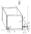
- a so-said base piece of furniture is schematically shown, which, e.g., is a part of a kitchen fitted with modular pieces of furniture, which base piece of furniture is mounted against a wall 11, only resting on a set of rear feet 12 (therefore, off barycentre), fastened onto the bottom 13 of the base piece of furniture in such as position as to define between them and the wall 11 a free chamber 14 suitable for housing service ducts and cable (water, town-gas, electrical energy).
- the free chamber 14 can be closed by applying to the feet 12 a customary wainscot 15 which is provided, for that purpose, with elements 16 of known type, by means it can be hooked to the same feet 12.
- the feet 12 will be such as to secure the base piece of furniture 10 to stably rest on the floor 17, so that such a base piece of furniture is capable of supporting considerable working loads, deriving, e.g., from the application of a worktop, of a sink, and anyway from the containment of heavy things, or of pieces of furniture of column type with built-in electrical household appliances.
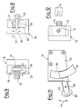
- the base piece of furniture 10 is prevented from overturning by being anchored to the wall 11 by means of the anchoring system according to the present invention, which comprises, in combination, a perforated bar or beam 18 fastened to the wall 11 in the nearby of the top plane of the same piece of furniture 10, to which beam anchoring devices 19 are constrained, which can be registered in position, and are generally fixed in correspondence of the shoulders of the piece of furniture 10.
- the anchoring system according to the present invention, which comprises, in combination, a perforated bar or beam 18 fastened to the wall 11 in the nearby of the top plane of the same piece of furniture 10, to which beam anchoring devices 19 are constrained, which can be registered in position, and are generally fixed in correspondence of the shoulders of the piece of furniture 10.
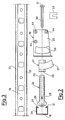
- the beam 18 has a generally "C"-shaped cross-section, and from its flanges 20 lips 21 jut out, which converge towards the interior of the beam; the purpose of said lips 21 will result clearly from the following.
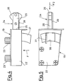
- the anchoring device 19 is structurally formed by a box-like body made from plastic material 22 which has a generally parallelepipedal shape. From a longitudinal side wall of said body, pegs 23 extend for the purpose of achieving a pressure-fastening inside complementary bores provided in the shoulder of the piece of furniture 10.
- Said box-like body 22 houses a rod-shaped anchoring element 24, a portion of which juts out from the open front side 25 of the same body 22 and ends with a lobe-shaped head 26.
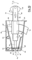
- the anchoring element 24 is structurally formed by a sleeve 27 through which a rod 28, adjustable in length, runs; for that purpose, the rod 28 is fastened to a fork 29, in different positions (see Figure 15).
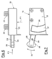
- a screw 30 is screwed down, the head 31 of which is loosely housed inside a suitable seat 32 provided inside the box-like body 22 and is constrained inside said seat by means of a "U"-piece 33 which enters purposely provided guide slots 40.
- the head 31 of the screw constitutes an articulation member for the anchoring element 24, which can both swing in the directions as shown by arrow 34 ( Figures 7, 10 and 11), and rotate around its own axis in the directions as indicated by the arrow 35, between the two positions as shown in Figures 8 and 9. Furthermore, by acting on the screw 30, the anchoring element 24 can be also driven to translate in the directions as indicated by the arrow 36 ( Figure 10).
- the tang 37 extends outwards from the box-like body 22, passing through the arcuate slot 38; when, on the contrary, the anchoring element 24 is in its operating position as shown in Figures 7, 9 and 11, the tang 37 is partially or totally contained inside the same complementary arcuate slot 38, anyway coplanar with the wall of the box-like body 22.
- the sleeve 27 is constrained to the box-like body 22 as regards the translation, but not as regards the rotation.
- the anchoring element 24 and the sleeve 27 are integral with each other as regards their swinging around the theoretical centre "C" in the directions as shown by the arrow 34 and as regards their rotation around their own axis in the directions as shown by the arrow 35, but not as regards the translation: in fact, the anchoring element 24 driven by the screw 30 can freely translate in the directions as shown by the arrow 36 by sliding inside the interior of the sleeve 27.
- the sleeve 27 has a cross-section of polygonal shape with rounded edges, so that its sides 39 cooperate with the inner walls of the box-like body 22 in order to positively determine the two positions as depicted in Figures 8 and 9; such positions are spring-wise determined thanks to the characteristics of elastic yielding of the opposite walls of the box-like body 22, preferably made from plastic material.
- the piece of furniture 10, resting on its feet 12 (with said feet being preferably provided with a plate 41 of adequate size) and provided with a plurality of devices 19, is approached to the wall 11 on which the beam 18 is already fixed (by means of screw anchors and/or screws), at a height approximately corresponding to the height of the devices 19.
- the devices 19 are prearranged with the anchoring element 24 being in its non-operating position as shown in Figures 4, 5 and 8, so that the head 26 can be inserted into the interior of the structural shape 18 in the position as shown in Figure 13.
- a slot 43 can be provided in advance. Now, it is just necessary to rotate, by means of the tang 37, the anchoring element 24 into its vertical operating condition as shown in Figures 7, 9, 10, 11 and 14, in order to prevent the head 26 from being prone to be slid out from the lips 21 of the structural shape 18.
- the piece of furniture 10 is perfectly aligned to the wall 11, thus securing a perfect stability of the same piece of furniture 10.
- the length of the anchoring element 24 can be adjusted in advance as a function of the distance of the device 19 from the wall 11.
- system according to the present invention could be practiced as well without the sleeve 27 and the relevant drive tang 37.
Landscapes
- Supports Or Holders For Household Use (AREA)
- Furniture Connections (AREA)
- Wing Frames And Configurations (AREA)
Claims (9)
- Wandbefestigungsvorrichtung für freitragende Möbel (10) des Typs, der in Kombination umfaßt: eine Konstruktionsform (18), die dazu geeignet ist, an der Wand (11) befestigt zu werden und eine Verankerungseinrichtung (19), die dazu geeignet ist, an dem genannten Möbel (10) befestigt und stabil wechselseitig mit der genannten Konstruktionsform (18) verbunden zu werden, wobei die genannte Verankerungseinrichtung (19) aus einem kastenartigen Körper (22) besteht, aus dem ein Verankerungselement (24) herausragt, das in einen geformten Kopf (26) ausläuft und dazu ausgebildet ist, mittels einer Antriebseinrichtung in Translation in bezug auf seine Längsachse bewegt zu werden, dadurch gekennzeichnet, daß das Verankerungselement (24) am genannten Körper (22) freischwingend befestigt und dazu ausgebildet ist, gleichfalls mittels einer Antriebseinrichtung (37) in bezug auf seine Längsachse rotiert zu werden, sodaß das genannte Verankerungselement (24) zwischen einer ersten Stellung, in der der genannte geformte Kopf (26) aus der genannten Konstruktionsform (18) freigesetzt werden kann, und einer zweiten Stellung rotiert werden kann, in der der genannte geformte Kopf (26) an der genannten Konstruktionsform (18) festgehalten wird, wobei die genannte Befestigung durch Translationsbewegung des genannten Verankerungselementes (24) stabilisiert wird.
- Vorrichtung nach Anspruch 1, dadurch gekennzeichnet, daß die Translationsbewegung des genannten Verankerungselements (24) mittels einer ersten Antriebseinrichtung (30) angetrieben wird, während seine Drehung um seine eigene Achse mittels einer zweiten Antriebseinrichtung (37) angetrieben wird.
- Befestigungsvorrichtung nach Anspruch 1 und 2, dadurch gekennzeichnet, daß das genannte Verankerungselement (24) strukturell von einer Hülse (27) gebildet wird, durch die sich eine Stange (28) erstreckt, wobei die genannte Stange (28) im genannten geformten Kopf (26) endet und die genannte Hülse (27) unlösbar bzw. formschlüssig an der genannten Stange (28) in bezug auf die Rotation, nicht aber auf die Translation befestigt ist und die genannte zweite Antriebseinrichtung (37) unlösbar bzw. formschlüssig mit der genannten Hülse (27) verbunden ist.
- Vorrichtung nach Anspruch 3, dadurch gekennzeichnet, daß die äußere Einfassung der genannten Hülse (27) mit einer solchen konturierten Form (39) ausgebildet ist, daß sie mit den einander gegenüberliegenden Wänden des kastenartigen Körpers (22) zusammenwirkt, um beide der vorstehend angeführten Stellungen des Verankerungselementes zwangsläufig durch Federwirkung festzulegen.
- Vorrichtung nach Anspruch 2, dadurch gekennzeichnet, daß die genannte zweite Antriebseinrichtung aus einem Heft (37) besteht, das sich seitlich nach außen durch einen Schlitz (38) erstreckt, der im genannten kastenartigen Körper (22) ausgebildet ist.
- Vorrichtung nach Anspruch 1, dadurch gekennzeichnet, daß die genannte erste Antriebseinrichtung aus einer Schraube (30) besteht, die am Ende des genannten Verankerungselementes (24) gegenüber dem genannten geformten Kopf (26) festgeschraubt ist. wobei der Antriebskopf (31) der genannten Schraube (30) lose innerhalb einer Kammer (32) aufgenommen ist, die an Ende des genannten kastenartigen Körpers (22) vorgesehen ist, der gegenüber jenem Ende gelegen ist, aus dem das genannte Verankerungselement (24) herausragt , wodurch die genannte Schraube (30) ein Drehelement für das genannte Verankerungselement (24) bildet.
- Vorrichtung nach Anspruch 1, dadurch gekennzeichnet, daß das genannte Verankerungselement (24) ein Element von variabler Länge ist.
- Vorrichtung nach Anspruch 1, dadurch gekennzeichnet, daß die genannte Konstruktionsform (18) einen im wesentlichen C-förmigen Querschnitt aufweist, aus dessen Flanschen (20) sich Lippen (21) erstrecken, die auf das Innere der genannten Konstruktionsform hin konvergieren, auf welchen Lippen (21) der genannte geformte Kopf (26) des genannten Verankerungselementes in der genannten zweiten Stellung desselben in Eingriff gebracht wird.
- Vorrichtung nach Anspruch 1, dadurch gekennzeichnet, daß der genannte Kopf (26) mit einem im wesentlichen lappenförmigen Umriß ausgebildet ist, sodaß er gleichzeitig frei schwingen und innerhalb des Inneren der Konstruktionsform (18) in Eingriff stehen kann.
Applications Claiming Priority (2)
| Application Number | Priority Date | Filing Date | Title |
|---|---|---|---|
| IT20654/88A IT1218247B (it) | 1988-05-20 | 1988-05-20 | Sistema perfezionamento per il montaggio a parete di un mobile a sbalzo |
| IT2065488 | 1988-05-20 |
Publications (3)
| Publication Number | Publication Date |
|---|---|
| EP0342724A2 EP0342724A2 (de) | 1989-11-23 |
| EP0342724A3 EP0342724A3 (de) | 1991-12-11 |
| EP0342724B1 true EP0342724B1 (de) | 1995-02-15 |
Family
ID=11170103
Family Applications (1)
| Application Number | Title | Priority Date | Filing Date |
|---|---|---|---|
| EP89200981A Expired - Lifetime EP0342724B1 (de) | 1988-05-20 | 1989-04-18 | Wandbefestigungsvorrichtung für freitragende Möbel |
Country Status (5)
| Country | Link |
|---|---|
| US (1) | US4936534A (de) |
| EP (1) | EP0342724B1 (de) |
| AT (1) | ATE118317T1 (de) |
| DE (1) | DE68921093T2 (de) |
| IT (1) | IT1218247B (de) |
Families Citing this family (11)
| Publication number | Priority date | Publication date | Assignee | Title |
|---|---|---|---|---|
| ES2074523T3 (es) * | 1989-03-20 | 1995-09-16 | Camar Spa | Dispositivo oculto para montar en pared un elemento mobiliario de pared. |
| GB2269981A (en) * | 1992-08-25 | 1994-03-02 | Titus Int Ltd | "Mounting device" |
| DE19711594A1 (de) * | 1997-03-20 | 1998-09-24 | Dornier Gmbh Lindauer | Vorrichtung zur Führung und Lagerung eines Greifertragorganes in Webmaschinen |
| US6073399A (en) * | 1998-01-28 | 2000-06-13 | Steelcase Development Inc. | Post and beam supported slatwall |
| IT1392140B1 (it) | 2008-07-17 | 2012-02-22 | Leonardo Srl | Reggipensile con mezzi perfezionati di fissaggio alla spalla del mobile pensile |
| IT1390845B1 (it) * | 2008-07-29 | 2011-10-19 | Leonardo Srl | Gruppo reggipensile regolabile per l'ancoraggio a parete di un mobile pensile |
| IT1391746B1 (it) * | 2008-07-29 | 2012-01-27 | Leonardo Srl | Gruppo reggipensile regolabile per l'ancoraggio a parete di un mobile pensile, con mezzi perfezionati di fissaggio alla spalla del mobile pensile |
| IT1393831B1 (it) * | 2009-04-24 | 2012-05-11 | Leonardo Srl | Sistema di antisganciamento per mobili pensili |
| DE102009049929B3 (de) * | 2009-09-16 | 2011-06-16 | Alno Ag | Hängeschrankbefestigungsvorrichtung |
| GB201305510D0 (en) | 2013-03-15 | 2013-05-08 | Leevw Jon O Van | Mountable furniture system |
| EP3175126B1 (de) | 2015-06-09 | 2020-08-19 | Dirtt Environmental Solutions, Ltd. | Modulare wandsysteme mit verschiebbarem möbelstück |
Family Cites Families (8)
| Publication number | Priority date | Publication date | Assignee | Title |
|---|---|---|---|---|
| US3737135A (en) * | 1971-09-20 | 1973-06-05 | Bertolini Engin Co Inc | Locking device |
| US3872555A (en) * | 1972-05-12 | 1975-03-25 | Value Engineering Company | Freight container coupler |
| CA989578A (en) * | 1972-09-25 | 1976-05-25 | George A.B. Austin | Fastenings for roof and wall sheeting |
| FR2350487A1 (fr) * | 1976-05-06 | 1977-12-02 | Legrand Leon | Dispositif pour la fixation reglable d'un element mural de meuble sur une paroi |
| DE2641648A1 (de) * | 1976-09-16 | 1978-03-30 | Hettich Hetal Werke | Verstellbare aufhaengevorrichtung fuer moebelstuecke |
| DE3017940A1 (de) * | 1980-05-10 | 1981-11-19 | Alfred Grass GmbH Metallwarenfabrik, 6973 Höchst, Vorarlberg | Abstandshalter fuer haengeschraenke u.dgl. |
| DE3409227A1 (de) * | 1983-09-26 | 1985-09-19 | Hetal-Werke Franz Hettich Gmbh & Co, 7297 Alpirsbach | Beschlag zum haengenden befestigen eines wandschrankes an einer gebaeudewand |
| DE3334768C2 (de) * | 1983-09-26 | 1987-03-26 | Hetal-Werke Franz Hettich Gmbh & Co, 7297 Alpirsbach | Beschlag zum hängenden Befestigen eines Wandschrankes an einer Gebäudewand |
-
1988
- 1988-05-20 IT IT20654/88A patent/IT1218247B/it active
-
1989
- 1989-04-18 EP EP89200981A patent/EP0342724B1/de not_active Expired - Lifetime
- 1989-04-18 AT AT89200981T patent/ATE118317T1/de not_active IP Right Cessation
- 1989-04-18 DE DE68921093T patent/DE68921093T2/de not_active Expired - Fee Related
- 1989-04-20 US US07/340,859 patent/US4936534A/en not_active Expired - Lifetime
Also Published As
| Publication number | Publication date |
|---|---|
| DE68921093T2 (de) | 1995-09-14 |
| IT8820654A0 (it) | 1988-05-20 |
| EP0342724A3 (de) | 1991-12-11 |
| ATE118317T1 (de) | 1995-03-15 |
| IT1218247B (it) | 1990-04-12 |
| EP0342724A2 (de) | 1989-11-23 |
| US4936534A (en) | 1990-06-26 |
| DE68921093D1 (de) | 1995-03-23 |
Similar Documents
| Publication | Publication Date | Title |
|---|---|---|
| EP0342724B1 (de) | Wandbefestigungsvorrichtung für freitragende Möbel | |
| US6349907B1 (en) | Height adjustable glide device | |
| US3771466A (en) | Pole shelving | |
| US3750989A (en) | Adjustable appliance support | |
| CA2025708C (en) | Stirrup assembly for examination table | |
| USRE37943E1 (en) | Rotary shelf mechanism | |
| US5285733A (en) | Height-adjustable table with a linear or straight guide | |
| US3944308A (en) | Frame for supporting articles | |
| KR101804752B1 (ko) | 벽부형 다목적 보관대 | |
| US3920276A (en) | Demountable swing seat construction for counters and the like | |
| US3698780A (en) | Under-cabinet radio | |
| USD362051S (en) | Furniture unit with wash basin, mirror, lateral cupboard and suspended drawers | |
| CA2071423A1 (en) | Method and Means for Dishwasher Tub and Support Assembly | |
| US6345795B1 (en) | Shelf bracket | |
| US3427024A (en) | Swing set construction | |
| EP2390447B1 (de) | Halterung mit Frontkupplung für Laufwagen von Schiebeflügeln oder -türen | |
| US6663182B1 (en) | Adjustable armrest for chairs | |
| US4009918A (en) | Height adjustable cabinet | |
| MX9505073A (es) | Herraje para ataud removible externamente que se traba de manera corrediza. | |
| US6176400B1 (en) | Garment supporting stand | |
| US4955094A (en) | Head-board recliner using the only one hinge | |
| KR100750904B1 (ko) | 조립식 진열대 결합구조 | |
| GB2271360A (en) | A collapsible ironing board assembly | |
| US3512742A (en) | Cable splicer's seat | |
| ATE201061T1 (de) | Möbel mit belüftung |
Legal Events
| Date | Code | Title | Description |
|---|---|---|---|
| PUAI | Public reference made under article 153(3) epc to a published international application that has entered the european phase |
Free format text: ORIGINAL CODE: 0009012 |
|
| AK | Designated contracting states |
Kind code of ref document: A2 Designated state(s): AT BE CH DE ES FR GB GR LI NL SE |
|
| PUAL | Search report despatched |
Free format text: ORIGINAL CODE: 0009013 |
|
| AK | Designated contracting states |
Kind code of ref document: A3 Designated state(s): AT BE CH DE ES FR GB GR LI NL SE |
|
| 17P | Request for examination filed |
Effective date: 19920414 |
|
| 17Q | First examination report despatched |
Effective date: 19930924 |
|
| GRAA | (expected) grant |
Free format text: ORIGINAL CODE: 0009210 |
|
| AK | Designated contracting states |
Kind code of ref document: B1 Designated state(s): AT BE CH DE ES FR GB GR LI NL SE |
|
| PG25 | Lapsed in a contracting state [announced via postgrant information from national office to epo] |
Ref country code: NL Effective date: 19950215 Ref country code: LI Effective date: 19950215 Ref country code: GR Free format text: LAPSE BECAUSE OF FAILURE TO SUBMIT A TRANSLATION OF THE DESCRIPTION OR TO PAY THE FEE WITHIN THE PRESCRIBED TIME-LIMIT Effective date: 19950215 Ref country code: FR Effective date: 19950215 Ref country code: ES Free format text: THE PATENT HAS BEEN ANNULLED BY A DECISION OF A NATIONAL AUTHORITY Effective date: 19950215 Ref country code: CH Effective date: 19950215 Ref country code: BE Effective date: 19950215 Ref country code: AT Effective date: 19950215 |
|
| REF | Corresponds to: |
Ref document number: 118317 Country of ref document: AT Date of ref document: 19950315 Kind code of ref document: T |
|
| REF | Corresponds to: |
Ref document number: 68921093 Country of ref document: DE Date of ref document: 19950323 |
|
| PG25 | Lapsed in a contracting state [announced via postgrant information from national office to epo] |
Ref country code: SE Effective date: 19950515 Ref country code: GB Effective date: 19950515 |
|
| REG | Reference to a national code |
Ref country code: CH Ref legal event code: PL |
|
| EN | Fr: translation not filed | ||
| NLV1 | Nl: lapsed or annulled due to failure to fulfill the requirements of art. 29p and 29m of the patents act | ||
| PLBE | No opposition filed within time limit |
Free format text: ORIGINAL CODE: 0009261 |
|
| STAA | Information on the status of an ep patent application or granted ep patent |
Free format text: STATUS: NO OPPOSITION FILED WITHIN TIME LIMIT |
|
| GBPC | Gb: european patent ceased through non-payment of renewal fee |
Effective date: 19950515 |
|
| 26N | No opposition filed | ||
| PGFP | Annual fee paid to national office [announced via postgrant information from national office to epo] |
Ref country code: DE Payment date: 19960403 Year of fee payment: 8 |
|
| PG25 | Lapsed in a contracting state [announced via postgrant information from national office to epo] |
Ref country code: DE Free format text: LAPSE BECAUSE OF NON-PAYMENT OF DUE FEES Effective date: 19980101 |