EP0342687A2 - Coded speech communication system having code books for synthesizing small-amplitude components - Google Patents
Coded speech communication system having code books for synthesizing small-amplitude components Download PDFInfo
- Publication number
- EP0342687A2 EP0342687A2 EP89109022A EP89109022A EP0342687A2 EP 0342687 A2 EP0342687 A2 EP 0342687A2 EP 89109022 A EP89109022 A EP 89109022A EP 89109022 A EP89109022 A EP 89109022A EP 0342687 A2 EP0342687 A2 EP 0342687A2
- Authority
- EP
- European Patent Office
- Prior art keywords
- signal
- excitation pulses
- speech
- gain
- coded
- Prior art date
- Legal status (The legal status is an assumption and is not a legal conclusion. Google has not performed a legal analysis and makes no representation as to the accuracy of the status listed.)
- Granted
Links
- 238000004891 communication Methods 0.000 title claims abstract description 26
- 230000002194 synthesizing effect Effects 0.000 title description 2
- 230000005284 excitation Effects 0.000 claims abstract description 92
- 230000003595 spectral effect Effects 0.000 claims abstract description 63
- 230000004044 response Effects 0.000 claims abstract description 35
- 230000015572 biosynthetic process Effects 0.000 claims description 22
- 238000003786 synthesis reaction Methods 0.000 claims description 22
- 230000005540 biological transmission Effects 0.000 claims description 14
- 238000001514 detection method Methods 0.000 claims description 9
- 238000000034 method Methods 0.000 claims description 7
- 230000008569 process Effects 0.000 claims description 5
- 230000010354 integration Effects 0.000 claims description 3
- 239000000470 constituent Substances 0.000 claims 3
- 230000011664 signaling Effects 0.000 claims 3
- 238000004364 calculation method Methods 0.000 abstract description 43
- 238000009432 framing Methods 0.000 description 12
- 238000010586 diagram Methods 0.000 description 9
- 230000004048 modification Effects 0.000 description 7
- 238000012986 modification Methods 0.000 description 7
- 238000013139 quantization Methods 0.000 description 4
- 238000011084 recovery Methods 0.000 description 4
- 230000008878 coupling Effects 0.000 description 3
- 238000010168 coupling process Methods 0.000 description 3
- 238000005859 coupling reaction Methods 0.000 description 3
- 238000001208 nuclear magnetic resonance pulse sequence Methods 0.000 description 3
- 239000002360 explosive Substances 0.000 description 2
- 230000003044 adaptive effect Effects 0.000 description 1
- 238000010420 art technique Methods 0.000 description 1
- 238000005314 correlation function Methods 0.000 description 1
- 230000008030 elimination Effects 0.000 description 1
- 238000003379 elimination reaction Methods 0.000 description 1
- 239000000284 extract Substances 0.000 description 1
- 238000005070 sampling Methods 0.000 description 1
- 238000010845 search algorithm Methods 0.000 description 1
- 230000001755 vocal effect Effects 0.000 description 1
- 238000005303 weighing Methods 0.000 description 1
Images


Classifications
-
- G—PHYSICS
- G10—MUSICAL INSTRUMENTS; ACOUSTICS
- G10L—SPEECH ANALYSIS TECHNIQUES OR SPEECH SYNTHESIS; SPEECH RECOGNITION; SPEECH OR VOICE PROCESSING TECHNIQUES; SPEECH OR AUDIO CODING OR DECODING
- G10L19/00—Speech or audio signals analysis-synthesis techniques for redundancy reduction, e.g. in vocoders; Coding or decoding of speech or audio signals, using source filter models or psychoacoustic analysis
- G10L19/04—Speech or audio signals analysis-synthesis techniques for redundancy reduction, e.g. in vocoders; Coding or decoding of speech or audio signals, using source filter models or psychoacoustic analysis using predictive techniques
- G10L19/06—Determination or coding of the spectral characteristics, e.g. of the short-term prediction coefficients
-
- G—PHYSICS
- G10—MUSICAL INSTRUMENTS; ACOUSTICS
- G10L—SPEECH ANALYSIS TECHNIQUES OR SPEECH SYNTHESIS; SPEECH RECOGNITION; SPEECH OR VOICE PROCESSING TECHNIQUES; SPEECH OR AUDIO CODING OR DECODING
- G10L19/00—Speech or audio signals analysis-synthesis techniques for redundancy reduction, e.g. in vocoders; Coding or decoding of speech or audio signals, using source filter models or psychoacoustic analysis
- G10L19/04—Speech or audio signals analysis-synthesis techniques for redundancy reduction, e.g. in vocoders; Coding or decoding of speech or audio signals, using source filter models or psychoacoustic analysis using predictive techniques
- G10L19/08—Determination or coding of the excitation function; Determination or coding of the long-term prediction parameters
- G10L19/083—Determination or coding of the excitation function; Determination or coding of the long-term prediction parameters the excitation function being an excitation gain
-
- G—PHYSICS
- G10—MUSICAL INSTRUMENTS; ACOUSTICS
- G10L—SPEECH ANALYSIS TECHNIQUES OR SPEECH SYNTHESIS; SPEECH RECOGNITION; SPEECH OR VOICE PROCESSING TECHNIQUES; SPEECH OR AUDIO CODING OR DECODING
- G10L19/00—Speech or audio signals analysis-synthesis techniques for redundancy reduction, e.g. in vocoders; Coding or decoding of speech or audio signals, using source filter models or psychoacoustic analysis
- G10L19/04—Speech or audio signals analysis-synthesis techniques for redundancy reduction, e.g. in vocoders; Coding or decoding of speech or audio signals, using source filter models or psychoacoustic analysis using predictive techniques
- G10L19/08—Determination or coding of the excitation function; Determination or coding of the long-term prediction parameters
- G10L19/10—Determination or coding of the excitation function; Determination or coding of the long-term prediction parameters the excitation function being a multipulse excitation
-
- G—PHYSICS
- G10—MUSICAL INSTRUMENTS; ACOUSTICS
- G10L—SPEECH ANALYSIS TECHNIQUES OR SPEECH SYNTHESIS; SPEECH RECOGNITION; SPEECH OR VOICE PROCESSING TECHNIQUES; SPEECH OR AUDIO CODING OR DECODING
- G10L19/00—Speech or audio signals analysis-synthesis techniques for redundancy reduction, e.g. in vocoders; Coding or decoding of speech or audio signals, using source filter models or psychoacoustic analysis
- G10L2019/0001—Codebooks
- G10L2019/0003—Backward prediction of gain
-
- G—PHYSICS
- G10—MUSICAL INSTRUMENTS; ACOUSTICS
- G10L—SPEECH ANALYSIS TECHNIQUES OR SPEECH SYNTHESIS; SPEECH RECOGNITION; SPEECH OR VOICE PROCESSING TECHNIQUES; SPEECH OR AUDIO CODING OR DECODING
- G10L19/00—Speech or audio signals analysis-synthesis techniques for redundancy reduction, e.g. in vocoders; Coding or decoding of speech or audio signals, using source filter models or psychoacoustic analysis
- G10L2019/0001—Codebooks
- G10L2019/0004—Design or structure of the codebook
- G10L2019/0005—Multi-stage vector quantisation
-
- G—PHYSICS
- G10—MUSICAL INSTRUMENTS; ACOUSTICS
- G10L—SPEECH ANALYSIS TECHNIQUES OR SPEECH SYNTHESIS; SPEECH RECOGNITION; SPEECH OR VOICE PROCESSING TECHNIQUES; SPEECH OR AUDIO CODING OR DECODING
- G10L19/00—Speech or audio signals analysis-synthesis techniques for redundancy reduction, e.g. in vocoders; Coding or decoding of speech or audio signals, using source filter models or psychoacoustic analysis
- G10L2019/0001—Codebooks
- G10L2019/0011—Long term prediction filters, i.e. pitch estimation
-
- G—PHYSICS
- G10—MUSICAL INSTRUMENTS; ACOUSTICS
- G10L—SPEECH ANALYSIS TECHNIQUES OR SPEECH SYNTHESIS; SPEECH RECOGNITION; SPEECH OR VOICE PROCESSING TECHNIQUES; SPEECH OR AUDIO CODING OR DECODING
- G10L25/00—Speech or voice analysis techniques not restricted to a single one of groups G10L15/00 - G10L21/00
- G10L25/03—Speech or voice analysis techniques not restricted to a single one of groups G10L15/00 - G10L21/00 characterised by the type of extracted parameters
- G10L25/06—Speech or voice analysis techniques not restricted to a single one of groups G10L15/00 - G10L21/00 characterised by the type of extracted parameters the extracted parameters being correlation coefficients
-
- G—PHYSICS
- G10—MUSICAL INSTRUMENTS; ACOUSTICS
- G10L—SPEECH ANALYSIS TECHNIQUES OR SPEECH SYNTHESIS; SPEECH RECOGNITION; SPEECH OR VOICE PROCESSING TECHNIQUES; SPEECH OR AUDIO CODING OR DECODING
- G10L25/00—Speech or voice analysis techniques not restricted to a single one of groups G10L15/00 - G10L21/00
- G10L25/93—Discriminating between voiced and unvoiced parts of speech signals
Definitions
- the present invention relates generally to speech coding techniques and more specifically to a coded speech communication system.
- Araseki, Ozawa, Ono and Ochiai “Multi-Pulse Excited Speech Coder Based on Maximum Cross-correlation Search Algorithm” (GLOBECOM 83, IEEE Global Telecommunication, 23.3, 1983) describes transmission of coded speech signals at rates lower than 16 kb/s using a coded signal that represents the amplitudes and locations of main, or large-amplitude excitation pulses to be used as a speech source at the receive end for recovery of discrete speech samples as well as a coded filter coefficient that represents the vocal tract of the speech.
- the amplitudes and locations of the large-amplitude excitation pulses are derived by circuitry which is essentially formed by a subtractor and a feedback circuit which is connected between the output of the subtractor and one input thereof.
- the feedback circuit includes a weighting filter connected to the output of the subtractor, a calculation circuit, an excitation pulse generator and a synthesis filter.
- a series of discrete speech samples is applied to the other input of the subtractor to detect the difference between it and the output of synthesis filter.
- the calculation circuit determines the amplitude and location of a pulse to be generated in the excitation circuit and repeats this process to generate subsequent pulses until the energy of the difference at the output of the subtractor is reduced to a minimum.
- the quality of recovered speech of this approach is found to deteriorate significantly as the bit rate is reduced below some point.
- a similar problem occurs when the input speech is a high pitch voice, such as female voice, because it requires a much greater number of excitation pulses to synthesize the quality of the input speech in a given period of time (or frame) than is required for synthesizing the quality of low-pitch speech signals during that period. Therefore, difficulty has been encountered to reduce the number of excitation pulses for low-bit rate transmission without sacrificing the quality of recovered speech.
- Japanese Laid-Open Patent Publication Sho 60-51900 published March 23, 1985 describes a speech encoder in which the auto-correlation of spectral components of input speech samples and the cross-correlation between the input speech samples and the spectral components are determined to synthesize large-amplitude excitation pulses.
- the fine pitch structure of the input speech samples is also determined to synthesize the auxiliary, or small-amplitude components of the original speech.
- the correlation between small-amplitude components is too low to precisely synthesize such components.
- transmission begins with an excitation pulse having a larger amplitude and ends with a pulse having a smaller amplitude that is counted a predetermined number from the first. If a certain upper limit is reached before transmitting the last pulse, the number of small-amplitude excitation pulses that have been transmitted is not sufficient to approximate the original speech. Such a situation is likely to occur often in applications in which the bit rate is low.
- Another object of the present invention is provide speech coding which enables low-transmission of the coded speech with a minimum amount of complications.
- a speech encoder which analyzes a series of discrete speech samples and generates a first coded signal representative of the fine structure of the pitch of the speech samples and generates a second coded signal representative of the spectral characteristic of the speech samples.
- the amplitudes and locations of large-amplitude excitation pulses are determined from the fine pitch structure and the spectral characteristic of the speech samples. The difference between the speech samples and the large-amplitude excitation pulses is detected.
- Gain and index values of small-amplitude excitation pulses are determined by retrieving stored small-amplitude excitation pulses from a code book so that the retrieved small-amplitude excitation pulses approximate the difference, wherein the gain value represents the amplitude of the small-amplitude excitation pulses and the index value represents locations of the stored excitation pulses in the code book.
- the first, second and third coded signals and the gain and index values are transmitted through a communication channel to a distant end for recovery of large- and small-amplitude excitation pulses.
- the amplitudes and locations of large-amplitude excitation pulses are determined from the first and second coded signals as well as from the detected difference so that large-amplitude excitation pulses approximate the difference.
- the present invention provides a coded speech communication system which comprises a pitch analyzer and LPC (linear predictive coding) analyzer for analyzing a series of discrete speech samples and respectively generating a first signal representative of the fine structure of the pitch of the speech samples and a second signal representative of the spectral characteristic of the speech samples.
- a calculation circuit determines the amplitudes and locations of large-amplitude excitation pulses from the first and second signals and generates a third signal representative of the determined pulse amplitudes and locations.
- a small-amplitude excitation pulse calculator having a code book is provided to generate a fourth signal representative of small-amplitude excitation pulses.
- the first, second, third and fourth signals are multiplexed and transmitted through a communication channel.
- a replica of the large-amplitude excitation pulses is derived from the received first and third signals and a replica of the small-amplitude excitation pulses is derived from a code book in response to the received fourth signal. These replicas are modified with the second signal to recover a replica of the original speech samples.
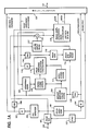
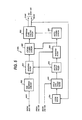
- the system comprises a speech encoder (Fig. 1A) and a speech decoder (Fig. 1 B).
- the speech encoder comprises a buffer, or framing circuit 101 which divides digitized speech samples (with a sampling frequency of 8 kHz, for example) into frames of, typically, 20-millisecond intervals in response to frame pulses supplied from a frame sync generator 122.
- Frame sync generator 122 also supplies a frame sync code to a multiplexer 120 to establish the frame start timing for signals to be transmitted over a communication channel 121 to the speech decoder.
- a pitch analyzer 102 is connected to the output of the framing circuit 101 to analyze the fine structure (pitch and amplitude) of the framed speech samples to generate a signal indicative of the pitch parameter of the original speech in a manner as described in B.S. Atal and M.R. Shroeder, "Adaptive Predictive Coding of Speech Signals", Bell System Technical Journal, October 1970, pages 1973 to 1986.
- the output of the pitch analyzer 102 is quantized by a quantizer 104 for translating the quantization levels of the pitch parameter so that it conforms to the transmission rate of the channel 121 and supplied to the multiplexer 120 on the one hand for transmission to the speech decoder.
- the quantized pitch parameter is supplied, on the other hand, to a dequantizer 105 and thence to an impulse response calculation unit 106 and a pitch synthesis filter 116.
- the function of the dequantizer 105 is a process which is inverse to that of the quantizer 104 to generate a signal identical to that which will be obtained at the speech decoder by reflecting the same quantization errors associated with the quantizer 104 into the process of impulse response calculation unit 106 and pitch synthesis filter 116 as those which will be reflected into the processes of the speech decoder.
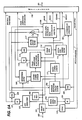
- the framed speech samples are also applied to a known LPC (linear predictive coding) analyzer 103 to analyze the spectral components of the speech samples in a known manner to generate a signal indicative of the spectral parameter of the original speech.
- the spectral parameter is quantized by a quantizer 107 and supplied on the one hand to the multiplexer 120, and supplied, on the other, through a dequantizer 108 to the impulse response calculation unit 106, a perceptual weighting filter 109, a spectral envelope filter 117 and to a small amplitude calculation unit 119.
- the functions of the quantizer 107 and dequantizer 108 are similar to those of the quantizer 104 and dequantizer 105 so that the quantization error associated with the quantizer 107 is reflected into the results of the various circuits that receive the dequantized spectral parameter in order to obtain signals identical to the corresponding signals which will be obtained at the speech decoder.
- the impulse response calculation unit 106 calculates the impulse responses of the pitch synthesis filter 116 and spectral envelope filter 117 in a manner as described in Japanese Laid-Open Patent Publication No. 60-51900.
- Perceptual weighting filter 109 provides variable weighting on a difference signal, which is detected by a subtractor 118 between a synthesized speech pulse from the output of spectral envelope filter 117 and the original speech sample from the framing circuit 101, in accordance with the dequantized spectral parameter from dequantizer 108 in a manner as described in the aforesaid Japanese Laid-Open Publication.
- Output signals from impulse response calculation unit 106 and perceptual weighting filter 109 are supplied to a cross-correlation detector 110 to determine the cross-correlation between the impulse responses of the filters 116 and 117 and the weighted speech difference signal from subtractor 118, the output of the cross-correlation detector 110 being coupled to a first input of a pulse amplitude and location calculation unit 112.
- the output of the impulse response calculator 106 is also applied to an auto-correlation detector 111 which determines the auto-correlation of the impulse responses and supply its output to a second input of the pulse amplitude and location calculator 112.
- the pulse amplitude and location calculator 112 calculates the amplitudes and locations of excitation pulses to be generated by a pulse generator 115.
- the output of pulse amplitude and location analyzer 112 is quantized by a quantizer 113 and supplied to multiplexer 117 on the one hand and supplied through a dequantizer 114 to the pulse generator 115 on the other.
- Excitation pulses of relatively large amplitudes are generated by pulse generator 115 and supplied to the pitch synthesis filter 116 where the excitation pulses are modified with the dequantized pitch parameter signal to synthesize the fine structure of the original speech.
- the functions of the quantizer 113 and dequantizer 114 are similar to those of the quantizer 104 and dequantizer 105 so that the quantization error associated with the quantizer 113 is reflected into the excitation pulses identical to the corresponding pulses which will be obtained at the speech decoder.
- the output of pitch synthesis filter 116 is applied to the spectral envelope filter 117 where it is further modified with the spectral parameter to synthesize the spectral envelope of the original speech.
- the output of spectral envelope filter 117 is combined with the original speech samples from framing circuit 101 in the subtractor 118.
- the difference output of subtractor 118 represents an error between the synthesized speech pulses and the speech samples in each frame.
- This error signal is fed back to the weighting filter 109 as mentioned above so that it is modified with the spectral-parameter-controlled weighting function and supplied to the cross-correlation detector 110.
- the feedback operation proceeds so that the error between original speech and synthetic speech reduces to zero. As a result, there exist as many excitation pulses in each frame as there are necessary to approximate the original speech.
- the output of subtractor 118 is also supplied to the small amplitude calculation unit 119.
- the quantized spectral parameter, pulse amplitudes and locations, pitch parameter, gain and index signals are multiplexed into a frame sequence by the multiplexer 120 and transmitted over the communication channel 12 to the speech decoder at the other end of the channel.
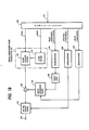
- the small amplitude calculation unit 119 is basically a feedback-controlled loop which essentially comprises a sub-framing circuit 150, a subtractor 151, a perceptual weighting filter 152, a code book 153, a gain circuit 154 and a spectral envelope filter 155.
- Sub-framing circuit subdivides the frame interval of the difference signal from subtractor 118 into sub-frames of 5 milliseconds each, for example.
- a difference between each sub-frame and the output of spectral envelope filter 155 is detected by subtractor 151 and supplied to weighting filter 152.
- weighting filter 152 is used to calculate the gain "g" of gain circuit 154 and an index signal to be applied to the code book 153 so that they minimize the difference, or error output of subtractor 151.
- Code book 153 stores speech signals in coded form representing small-amplitude pulses of random phase. One of the stored codes is selected in response to the index signal and supplied to the gain control circuit 154 where the gain of the selected code is controlled by the gain control signal "g" and fed to the spectral envelope filter 155.
- the error output E of subtractor 151 is given by: where, e(n) represents the input signal from subtractor 118, e(n) representing the output of spectral envelope filter 206, w(n) representing the impulse response of the weighting filter 202 and the symbol represents convolutional integration.
- Equation (1) can be rewritten as: the code-book that minimizes the error E can be selected so that it maximizes the second term of Equation (4) and hence the gain "g".
- FIG. 2S A specific embodiment of the small-amplitude excitation pulse calculation unit 119 is shown in Fig. 2S.
- Sub-frame signal e(n) from sub-framing circuit 200 is passed through perceptual weighing filter 201 having an impulse response w(n), so that it produces an output signal e w (n).
- a cross-correlation detector 202 receives output signals from weighting filters 201 and 206 to produce a signal representative of the cross-correlation between signals ⁇ w (n) and e w (n), or the numerator of Equation (4).
- the output of weighting filter 206 is further applied to an auto-correlation detector 207 to obtain a signal representative of the auto-correlation of signal ⁇ w (n), namely, the denominator of Equation (4).
- the output signals of both correlation detectors 202 and 207 are fed to an optimum gain calculation circuit 203 which arithmetically divides the signal from cross-correlation detector 202 by the signal from auto-correlation detector 207 to produce a signal representative of the gain "g" and proceeds to detect an index signal that corresponds to the gain "g".
- the index signal is supplied to code book 204 to select a corresponding code n(n) which is applied to spectral envelope filter 205 to produce a signal ⁇ (n), which is applied to weighting filter 206 to generate the signal ⁇ w (n) for application to correlation detectors 202 and 207.
- a feedback operation proceeds and the optimum gain calculator 203 will produce multiple gain values and one of which is detected as a maximum value which minimizes the error value E coupling to the multiplexer 120 and an index signal that corresponds to the maximum gain is selected for application to the code book 204 as well as to the multiplexer 120.
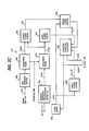
- An embodiment shown in Fig. 2C is to implement Equation (7).
- the difference signal e(n) from subtractor 118 is sub-divided by sub-framing circuit 300 and weighted by weighting filter 301 to produce a signal e w (n).
- a weighting filter 306 is supplied with a signal representing the impulse response h(n) of the spectral envelope filter 155 which is available from the impulse response calculation unit 106 of Fig. 1A.
- the output of weighting filter 306 is a signal h w (n).
- weighting filters 301 and 306 are supplied to a cross-correlation detector 302 to obtain a signal representing the cross-correlation ⁇ xh, which is supplied to a cross-correlation detector 303 to which the output of code book 305 is also applied.
- the cross-correlation detector 303 produces a signal representative of the numerator of Equation (7) and supplies it to an optimum gain calculation unit 304.
- An auto-correlation detector 307 is connected to the output of weighting filter 306 to supply a signal representing the auto-correlation R hh (O) (or energy of combined impulse response of the spectral envelope filter 155 and weighting filter 152) to the optimum gain calculation unit 304.
- the output of code book 305 is further coupled to an auto-correlation detector 308 to produce a signal representing R nn (O) of code-book signal n(n) for coupling to the optimum gain calculation unit 304.
- the latter multiplies calculates R hh (0) and R nn (0) to derive the denominator of Equation (7) and derives the gain "g" of Equation (7) by arithmetically dividing the output of cross-correlation detector 303 by the denominator just obtained above and detects an index signal that corresponds to the gain "g".
- the index signal is supplied to the code book 305 to read a code-book signal n(n).
- Multiple gain values are derived in a manner similar to that describe above as the feedback operation proceeds and a' maximum of the gain values which minimizes the error E is selected and supplied to the multiplexer 120 and a corresponding optimum value of index signal is derived for application to the multiplexer 120 as well as to the code book 305.
- the multiplexed frame sequence is separated into the individual component signals by a demultiplexer 130.
- the gain signal is supplied to a gain calculation unit 131 of a small-amplitude pulse generator 141 and the index signal is supplied to a code book 132 of the decoder 141 identical to the code book of the speech encoder.
- gain calculation unit 131 determines the amplitudes of a code-book signal that is selected by code book 132 in response to the index signal from the demultiplexer 130 and supplies its output to an adder 133 as a small-amplitude pulse sequence.
- the quantized signals including pulse amplitudes and locations, spectral parameter and pitch parameter are respectively dequantized by dequantizers 134, 138 and 139.
- the dequantized pulse amplitudes and locations signal is applied to a pulse generator 135 to generate excitation pulses, which are supplied to a pitch synthesis filter 136 to which the dequantized pitch parameter is also supplied to modify the filter response characteristic in accordance with the fine pitch structure of the coded speech signal. It is seen that the output of pitch synthesis filter 136 corresponds to the signal obtained at the output of pitch synthesis filter 116 of the speech encoder.
- the output of pitch synthesis filter 136 is supplied as a large-amplitude pulse sequence to the adder 133 and summed with the small-amplitude pulse sequence from gain calculation circuit 131 and supplied to a spectral envelope filter 137 to which the dequantized spectral parameter is applied to modify the summed signal from adder 133 to recover a replica of the original speech at the output terminal 140.
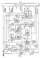
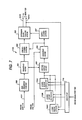
- FIG. 3A A modified embodiment of the present invention is shown in Figs. 3A and 3B.
- the speech encoder of this modification is similar to the previous embodiment with the exception that it additionally includes a voiced sound detector 400 connected to the outputs of framing circuit 101, pitch analyzer 102 and LPC analyzer 103 to discriminate between voiced and unvoiced sounds and generates a logic-1 or logic-0 output in response to the detection of a voiced or an unvoiced sound, respectively.
- a logic-1 is supplied from a voiced sound detector 400 as a disabling signal to the small-amplitude excitation pulse calculation unit 119 and multiplexed with other signals by the multiplexer 120 for transmission to the speech decoder.
- the small-amplitude calculation unit 119 is therefore disabled in response to the detection of a vowel, so that the index and gain signals are nullified and the disabling signal is transmitted to the speech decoder instead. Therefore, when vowels are being synthesized, the signal being transmitted to the speech decoder is composed exclusively of the quantized pulse amplitudes and locations signal, pitch and spectral parameter signals to permit the speech decoder to recover only large-amplitude pulses, and when consonants are being synthesized, the signal being transmitted is composed of the gain and index signals in addition to the quantized pulse amplitudes and locations signal and pitch and spectral parameter signals to permit the decoder to recover random-phase, small-amplitude pulses from the code book as well as large-amplitude pulses.
- the amount of information necessary to be transmitted to the speech decoder for the recovery of vowels can be reduced in this way.
- the elimination of the gain and index signals from the multiplexed signal is to improve the definition of unvoiced, or consonant components of the speech which will be recovered at the decoder.
- the disabling signal is also applied to the pulse amplitude and location calculation unit 112. In the absence of the disabling signal, the calculation circuit 112 calculates amplitudes and locations of a predetermined, greater number of excitation pulses, and in the presence of the disabling signal, it calculates the amplitudes and locations of a predetermined, smaller number of excitation pulses.
- the speech decoder of this modification extracts the disabling signal from the other multiplexed signals by the demultiplexer 130 and supplied to the gain calculation unit 131 and code book 132.
- the outputs of these circuits are nullified and no small-amplitude pulses are supplied to the adder 133 during the transmission of coded vowels.
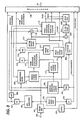
- FIG. 4A A second modification of the present invention is shown in Figs. 4A, 4B and 5.
- the speech encoder of this modification is similar to the embodiment of Fig. 3A with the exception that the pitch parameter signal from the output of dequantizer 105 is further supplied to small-amplitude excitation pulse calculation unit 119A to improve the degree of precision of vowels, or voiced sound components in addition to the precise definition of unvoiced, or consonants.
- the small-amplitude calculation unit 119A includes a pitch synthesis filter 600 to modify the output of code book 204 with the pitch parameter signal from dequantizer 105 and supplies its output to the spectral envelope filter 205. In this way, the small-amplitude pulses can be approximated more faithfully to the original speech.
- the speech decoder of this modification includes a pitch synthesis filter 500 as shown in Fig. 4B.
- Pitch synthesis filter 500 is connected between the output of gain calculation unit 131 and the adder 133 to modify the amplitude-controlled, small-amplitude pulses in accordance with the transmitted pitch parameter signal.
- Figs. 6A, 6B and 7 are illustrations of a third modified embodiment of the present invention.
- the speech encoder includes a vowel/consonant discriminator 700 connected to the output of framing circuit 101 and a consonant analyzer 701.
- Discriminator 700 analyzes the speech samples and determines whether it is vowel or consonant. If a vowel is detected, discriminator 700 applies a vowel-detect (logic-1) signal to pulse amplitude and location calculation unit 112 to perform amplitude and location calculations on a greater number of excitation pulses.
- the vowel-detect signal is also applied to small-amplitude excitation pulse calculation unit 119B to nullify its gain and index signals and further applied to the multiplexer 120 and sent to the speech decoder as a disabling signal in a manner similar to the previous embodiments.
- pulse amplitude and location calculation unit 112 responds to the absence of logic-1 signal from discriminator 700 and performs amplitude and location calculations on a smaller number of excitation pulses.
- Consonant analyzer 701 is connected to the output of framing circuit 101 to analyze the consonant of input signal to discriminate between "fricative", “explosive” and “other” consonant components using a known analyzing technique and generates a select code to small-amplitude excitation pulse calculation unit 119B and multiplexer 120 to be multiplexed with other signals.
- small-amplitude calculation unit 119B includes a selector 710 connected to the output of consonant analyzer 700 and a plurality of code books 720A, 720B and 720C which store small-amplitude code-book data corresponding respectively to the "fricative", “explosive” and “others” components.
- Selector 710 selects one of the code books in accordance with the select code from the analyzer 701. In this way, a replica of a more faithful reproduction of small-amplitude pulses can be realized.
- the speech decoder separates the select code from the other signals by the demultiplexer 130 and additionally includes a selector 730 which receives the demultiplexed select code to select one of code books 740A, 740B and 740C which correspond respectively to the code books 720A, 720B and 720C.
- the index signal from demultiplexer 130 is applied to all the code books 740.
- One of the code books 740A, 740B 740C, which is selected, receives the index signal and generates a code-book signal for coupling to the gain calculation unit 131.
- FIG. 8 A further modification of the invention is shown in Fig. 8 in which the gain and index outputs of the small-amplitude calculation unit 119 are fed to a small-amplitude pulse generator 800 to reproduce the same small-amplitude pulses as those reconstructed in the speech decoder.
- the output of pulse generator 800 is supplied through a spectral envelope filter 810 to an adder 820 where it is summed with the output of spectral envelope filter 117.
- the output of adder 820 is supplied to one input of a decision circuit 830 for comparison with the output of framing circuit 101 and determines whether the recovered small-amplitude pulses are effective or ineffective.
- decision circuit 830 supplies a disabling signal to the small-amplitude excitation pulse calculation unit 119 as well as to multiplexer 120 to be multiplexed with other coded speech signals in order to disable the recovery of small-amplitude pulses at the speech-decoder.
Landscapes
- Engineering & Computer Science (AREA)
- Physics & Mathematics (AREA)
- Health & Medical Sciences (AREA)
- Signal Processing (AREA)
- Audiology, Speech & Language Pathology (AREA)
- Human Computer Interaction (AREA)
- Computational Linguistics (AREA)
- Acoustics & Sound (AREA)
- Multimedia (AREA)
- Spectroscopy & Molecular Physics (AREA)
- Transmission Systems Not Characterized By The Medium Used For Transmission (AREA)
- Analogue/Digital Conversion (AREA)
- Compression, Expansion, Code Conversion, And Decoders (AREA)
Abstract
Description
- The present invention relates generally to speech coding techniques and more specifically to a coded speech communication system.
- Araseki, Ozawa, Ono and Ochiai, "Multi-Pulse Excited Speech Coder Based on Maximum Cross-correlation Search Algorithm" (GLOBECOM 83, IEEE Global Telecommunication, 23.3, 1983) describes transmission of coded speech signals at rates lower than 16 kb/s using a coded signal that represents the amplitudes and locations of main, or large-amplitude excitation pulses to be used as a speech source at the receive end for recovery of discrete speech samples as well as a coded filter coefficient that represents the vocal tract of the speech. The amplitudes and locations of the large-amplitude excitation pulses are derived by circuitry which is essentially formed by a subtractor and a feedback circuit which is connected between the output of the subtractor and one input thereof. The feedback circuit includes a weighting filter connected to the output of the subtractor, a calculation circuit, an excitation pulse generator and a synthesis filter. A series of discrete speech samples is applied to the other input of the subtractor to detect the difference between it and the output of synthesis filter. The calculation circuit determines the amplitude and location of a pulse to be generated in the excitation circuit and repeats this process to generate subsequent pulses until the energy of the difference at the output of the subtractor is reduced to a minimum. However, the quality of recovered speech of this approach is found to deteriorate significantly as the bit rate is reduced below some point. A similar problem occurs when the input speech is a high pitch voice, such as female voice, because it requires a much greater number of excitation pulses to synthesize the quality of the input speech in a given period of time (or frame) than is required for synthesizing the quality of low-pitch speech signals during that period. Therefore, difficulty has been encountered to reduce the number of excitation pulses for low-bit rate transmission without sacrificing the quality of recovered speech.
- Japanese Laid-Open Patent Publication Sho 60-51900 published March 23, 1985 describes a speech encoder in which the auto-correlation of spectral components of input speech samples and the cross-correlation between the input speech samples and the spectral components are determined to synthesize large-amplitude excitation pulses. The fine pitch structure of the input speech samples is also determined to synthesize the auxiliary, or small-amplitude components of the original speech. However, the correlation between small-amplitude components is too low to precisely synthesize such components. In addition, transmission begins with an excitation pulse having a larger amplitude and ends with a pulse having a smaller amplitude that is counted a predetermined number from the first. If a certain upper limit is reached before transmitting the last pulse, the number of small-amplitude excitation pulses that have been transmitted is not sufficient to approximate the original speech. Such a situation is likely to occur often in applications in which the bit rate is low.
- It is therefore an object of the present invention to provide speech coding which permits low-bit transmission of a speech signal over a wide range of frequency components.
- Another object of the present invention is provide speech coding which enables low-transmission of the coded speech with a minimum amount of complications.
- According to a first aspect of the present invention, a speech encoder is provided which analyzes a series of discrete speech samples and generates a first coded signal representative of the fine structure of the pitch of the speech samples and generates a second coded signal representative of the spectral characteristic of the speech samples. The amplitudes and locations of large-amplitude excitation pulses are determined from the fine pitch structure and the spectral characteristic of the speech samples. The difference between the speech samples and the large-amplitude excitation pulses is detected. Gain and index values of small-amplitude excitation pulses are determined by retrieving stored small-amplitude excitation pulses from a code book so that the retrieved small-amplitude excitation pulses approximate the difference, wherein the gain value represents the amplitude of the small-amplitude excitation pulses and the index value represents locations of the stored excitation pulses in the code book. The first, second and third coded signals and the gain and index values are transmitted through a communication channel to a distant end for recovery of large- and small-amplitude excitation pulses.
- In a specific aspect, the amplitudes and locations of large-amplitude excitation pulses are determined from the first and second coded signals as well as from the detected difference so that large-amplitude excitation pulses approximate the difference.
- By the use of the code book, small-amplitude excitation pulses can be more precisely recovered at the distant end of the channel than is performed by the prior art techniques without substantially increasing the amount of information to be transmitted. 0
- According to a second aspect, the present invention provides a coded speech communication system which comprises a pitch analyzer and LPC (linear predictive coding) analyzer for analyzing a series of discrete speech samples and respectively generating a first signal representative of the fine structure of the pitch of the speech samples and a second signal representative of the spectral characteristic of the speech samples. A calculation circuit determines the amplitudes and locations of large-amplitude excitation pulses from the first and second signals and generates a third signal representative of the determined pulse amplitudes and locations. A small-amplitude excitation pulse calculator having a code book is provided to generate a fourth signal representative of small-amplitude excitation pulses. The first, second, third and fourth signals are multiplexed and transmitted through a communication channel. These signals are received at the opposite end of the channel. A replica of the large-amplitude excitation pulses is derived from the received first and third signals and a replica of the small-amplitude excitation pulses is derived from a code book in response to the received fourth signal. These replicas are modified with the second signal to recover a replica of the original speech samples.
- The present invention will be described in further detail with reference to the accompanying drawings, in which:
- Figs. 1A and 1B are block diagrams of a speech encoder and a speech decoder, respectively, according to an embodiment of the present invention;
- Fig 2A is a schematic block diagram of the basic structure of the small amplitude calculation unit of Fig. 1 A, and Figs. 2B and 2C are block diagrams of different forms of the invention;
- Figs. 3A and 3B are block diagrams of the speech encoder and speech decoder, respectively, of a second embodiment of the present invention;
- Figs. 4a and 4B are block diagrams of the speech encoder and speech decoder, respectively, of a third embodiment of the present invention; and
- Fig. 5 is a block diagram of the small-amplitude calculation unit of Fig. 4A;
- Figs. 6A and 6B are block diagrams of the speech encoder and speech decoder, respectively, of a fourth embodiment of the present invention;
- Fig. 7 is a block diagram of the small-amplitude calculation unit of Fig. 6A; and
- Flg. 8 is a block diagram of the speech encoder of a fifth embodiment of the present invention.
- Referring now to Figs. 1A and 1B, there is shown a coded speech communication system according to a first preferred embodiment of the present invention. The system comprises a speech encoder (Fig. 1A) and a speech decoder (Fig. 1 B). The speech encoder comprises a buffer, or
framing circuit 101 which divides digitized speech samples (with a sampling frequency of 8 kHz, for example) into frames of, typically, 20-millisecond intervals in response to frame pulses supplied from aframe sync generator 122.Frame sync generator 122 also supplies a frame sync code to amultiplexer 120 to establish the frame start timing for signals to be transmitted over acommunication channel 121 to the speech decoder. Apitch analyzer 102 is connected to the output of theframing circuit 101 to analyze the fine structure (pitch and amplitude) of the framed speech samples to generate a signal indicative of the pitch parameter of the original speech in a manner as described in B.S. Atal and M.R. Shroeder, "Adaptive Predictive Coding of Speech Signals", Bell System Technical Journal, October 1970, pages 1973 to 1986. The output of thepitch analyzer 102 is quantized by aquantizer 104 for translating the quantization levels of the pitch parameter so that it conforms to the transmission rate of thechannel 121 and supplied to themultiplexer 120 on the one hand for transmission to the speech decoder. The quantized pitch parameter is supplied, on the other hand, to adequantizer 105 and thence to an impulseresponse calculation unit 106 and apitch synthesis filter 116. The function of thedequantizer 105 is a process which is inverse to that of thequantizer 104 to generate a signal identical to that which will be obtained at the speech decoder by reflecting the same quantization errors associated with thequantizer 104 into the process of impulseresponse calculation unit 106 andpitch synthesis filter 116 as those which will be reflected into the processes of the speech decoder. - The framed speech samples are also applied to a known LPC (linear predictive coding)
analyzer 103 to analyze the spectral components of the speech samples in a known manner to generate a signal indicative of the spectral parameter of the original speech. The spectral parameter is quantized by aquantizer 107 and supplied on the one hand to themultiplexer 120, and supplied, on the other, through adequantizer 108 to the impulseresponse calculation unit 106, aperceptual weighting filter 109, aspectral envelope filter 117 and to a smallamplitude calculation unit 119. The functions of thequantizer 107 anddequantizer 108 are similar to those of thequantizer 104 anddequantizer 105 so that the quantization error associated with thequantizer 107 is reflected into the results of the various circuits that receive the dequantized spectral parameter in order to obtain signals identical to the corresponding signals which will be obtained at the speech decoder. - The impulse
response calculation unit 106 calculates the impulse responses of thepitch synthesis filter 116 andspectral envelope filter 117 in a manner as described in Japanese Laid-Open Patent Publication No. 60-51900.Perceptual weighting filter 109 provides variable weighting on a difference signal, which is detected by asubtractor 118 between a synthesized speech pulse from the output ofspectral envelope filter 117 and the original speech sample from the framingcircuit 101, in accordance with the dequantized spectral parameter fromdequantizer 108 in a manner as described in the aforesaid Japanese Laid-Open Publication. Output signals from impulseresponse calculation unit 106 andperceptual weighting filter 109 are supplied to across-correlation detector 110 to determine the cross-correlation between the impulse responses of thefilters subtractor 118, the output of thecross-correlation detector 110 being coupled to a first input of a pulse amplitude andlocation calculation unit 112. The output of theimpulse response calculator 106 is also applied to an auto-correlation detector 111 which determines the auto-correlation of the impulse responses and supply its output to a second input of the pulse amplitude andlocation calculator 112. - Using the outputs of these
correlation detectors location calculator 112 calculates the amplitudes and locations of excitation pulses to be generated by apulse generator 115. The output of pulse amplitude andlocation analyzer 112 is quantized by aquantizer 113 and supplied to multiplexer 117 on the one hand and supplied through adequantizer 114 to thepulse generator 115 on the other. Excitation pulses of relatively large amplitudes are generated bypulse generator 115 and supplied to thepitch synthesis filter 116 where the excitation pulses are modified with the dequantized pitch parameter signal to synthesize the fine structure of the original speech. The functions of thequantizer 113 anddequantizer 114 are similar to those of thequantizer 104 anddequantizer 105 so that the quantization error associated with thequantizer 113 is reflected into the excitation pulses identical to the corresponding pulses which will be obtained at the speech decoder. - The output of
pitch synthesis filter 116 is applied to thespectral envelope filter 117 where it is further modified with the spectral parameter to synthesize the spectral envelope of the original speech. The output ofspectral envelope filter 117 is combined with the original speech samples from framingcircuit 101 in thesubtractor 118. The difference output ofsubtractor 118 represents an error between the synthesized speech pulses and the speech samples in each frame. This error signal is fed back to theweighting filter 109 as mentioned above so that it is modified with the spectral-parameter-controlled weighting function and supplied to thecross-correlation detector 110. The feedback operation proceeds so that the error between original speech and synthetic speech reduces to zero. As a result, there exist as many excitation pulses in each frame as there are necessary to approximate the original speech. The output ofsubtractor 118 is also supplied to the smallamplitude calculation unit 119. - The quantized spectral parameter, pulse amplitudes and locations, pitch parameter, gain and index signals are multiplexed into a frame sequence by the
multiplexer 120 and transmitted over the communication channel 12 to the speech decoder at the other end of the channel. - As shown in Fig. 2A, the small
amplitude calculation unit 119 is basically a feedback-controlled loop which essentially comprises asub-framing circuit 150, asubtractor 151, aperceptual weighting filter 152, acode book 153, again circuit 154 and aspectral envelope filter 155. Sub-framing circuit subdivides the frame interval of the difference signal fromsubtractor 118 into sub-frames of 5 milliseconds each, for example. A difference between each sub-frame and the output ofspectral envelope filter 155 is detected bysubtractor 151 and supplied toweighting filter 152. The output ofweighting filter 152 is used to calculate the gain "g" ofgain circuit 154 and an index signal to be applied to thecode book 153 so that they minimize the difference, or error output ofsubtractor 151.Code book 153 stores speech signals in coded form representing small-amplitude pulses of random phase. One of the stored codes is selected in response to the index signal and supplied to thegain control circuit 154 where the gain of the selected code is controlled by the gain control signal "g" and fed to thespectral envelope filter 155. - It is seen from Fig. 2A that the error output E of
subtractor 151 is given by:
subtractor 118, e(n) representing the output ofspectral envelope filter 206, w(n) representing the impulse response of theweighting filter 202 and the symbol represents convolutional integration. The error E can be minimized when the following equation is obtained:
code book 153 in response to a given index signal, and h(n) represents the impulse response of thespectral envelope filter 155. It is seen that the denominator of Equation 2 is an auto-correlation (or covariance) of i w(n) and the numerator of the equation is a cross-correlation between ew(n) and ew(n). Since Equation (1) can be rewritten as:
- A specific embodiment of the small-amplitude excitation
pulse calculation unit 119 is shown in Fig. 2S. Sub-frame signal e(n) fromsub-framing circuit 200 is passed through perceptual weighingfilter 201 having an impulse response w(n), so that it produces an output signal ew(n). Across-correlation detector 202 receives output signals fromweighting filters weighting filter 206 is further applied to an auto-correlation detector 207 to obtain a signal representative of the auto-correlation of signal ẽw(n), namely, the denominator of Equation (4). The output signals of bothcorrelation detectors gain calculation circuit 203 which arithmetically divides the signal fromcross-correlation detector 202 by the signal from auto-correlation detector 207 to produce a signal representative of the gain "g" and proceeds to detect an index signal that corresponds to the gain "g". The index signal is supplied tocode book 204 to select a corresponding code n(n) which is applied tospectral envelope filter 205 to produce a signal ẽ(n), which is applied toweighting filter 206 to generate the signal ẽw(n) for application tocorrelation detectors optimum gain calculator 203 will produce multiple gain values and one of which is detected as a maximum value which minimizes the error value E coupling to themultiplexer 120 and an index signal that corresponds to the maximum gain is selected for application to thecode book 204 as well as to themultiplexer 120. - The amount of computations necessary to obtain ẽw(n) is substantial and hence the total amount of computations. However, the latter can be significantly reduced by the use of a cross-correlation function φxh which is given by:
- φxh = Σew(n)hw(n) (5)
- Since Equation (3a) can be rewritten as:
- ê w(n)=n(n)*hw(n) (6) substituting Equations (5) and (6) into Equation (2) results in the following equation:

- where, Rhh(O) represents the energy of combined impulse response of the
spectral envelope filter 155 andweighting filter 152 of Fig. 2A, or an auto-correlation of hw(n) and Rnn(O) represents the energy, or an auto-correlation of a code signal n(n) which is selected by thecode book 153 in response to a given index signal. - An embodiment shown in Fig. 2C is to implement Equation (7). The difference signal e(n) from
subtractor 118 is sub-divided bysub-framing circuit 300 and weighted byweighting filter 301 to produce a signal ew(n). Aweighting filter 306 is supplied with a signal representing the impulse response h(n) of thespectral envelope filter 155 which is available from the impulseresponse calculation unit 106 of Fig. 1A. The output ofweighting filter 306 is a signal hw(n). The outputs ofweighting filters cross-correlation detector 302 to obtain a signal representing the cross-correlation <xh, which is supplied to across-correlation detector 303 to which the output ofcode book 305 is also applied. Thus, thecross-correlation detector 303 produces a signal representative of the numerator of Equation (7) and supplies it to an optimumgain calculation unit 304. - An auto-
correlation detector 307 is connected to the output ofweighting filter 306 to supply a signal representing the auto-correlation Rhh(O) (or energy of combined impulse response of thespectral envelope filter 155 and weighting filter 152) to the optimumgain calculation unit 304. The output ofcode book 305 is further coupled to an auto-correlation detector 308 to produce a signal representing Rnn(O) of code-book signal n(n) for coupling to the optimumgain calculation unit 304. The latter multiplies calculates Rhh(0) and Rnn(0) to derive the denominator of Equation (7) and derives the gain "g" of Equation (7) by arithmetically dividing the output ofcross-correlation detector 303 by the denominator just obtained above and detects an index signal that corresponds to the gain "g". The index signal is supplied to thecode book 305 to read a code-book signal n(n). Multiple gain values are derived in a manner similar to that describe above as the feedback operation proceeds and a' maximum of the gain values which minimizes the error E is selected and supplied to themultiplexer 120 and a corresponding optimum value of index signal is derived for application to themultiplexer 120 as well as to thecode book 305. - In Fig. 1 B, the multiplexed frame sequence is separated into the individual component signals by a
demultiplexer 130. The gain signal is supplied to again calculation unit 131 of a small-amplitude pulse generator 141 and the index signal is supplied to acode book 132 of thedecoder 141 identical to the code book of the speech encoder. According to the gain signal from thedemultiplexer 130, gaincalculation unit 131 determines the amplitudes of a code-book signal that is selected bycode book 132 in response to the index signal from thedemultiplexer 130 and supplies its output to anadder 133 as a small-amplitude pulse sequence. The quantized signals including pulse amplitudes and locations, spectral parameter and pitch parameter are respectively dequantized bydequantizers pulse generator 135 to generate excitation pulses, which are supplied to apitch synthesis filter 136 to which the dequantized pitch parameter is also supplied to modify the filter response characteristic in accordance with the fine pitch structure of the coded speech signal. It is seen that the output ofpitch synthesis filter 136 corresponds to the signal obtained at the output ofpitch synthesis filter 116 of the speech encoder. The output ofpitch synthesis filter 136 is supplied as a large-amplitude pulse sequence to theadder 133 and summed with the small-amplitude pulse sequence fromgain calculation circuit 131 and supplied to aspectral envelope filter 137 to which the dequantized spectral parameter is applied to modify the summed signal fromadder 133 to recover a replica of the original speech at theoutput terminal 140. - A modified embodiment of the present invention is shown in Figs. 3A and 3B. In Fig. 3A, the speech encoder of this modification is similar to the previous embodiment with the exception that it additionally includes a
voiced sound detector 400 connected to the outputs of framingcircuit 101,pitch analyzer 102 andLPC analyzer 103 to discriminate between voiced and unvoiced sounds and generates a logic-1 or logic-0 output in response to the detection of a voiced or an unvoiced sound, respectively. When a voiced sound is detected, a logic-1 is supplied from avoiced sound detector 400 as a disabling signal to the small-amplitude excitationpulse calculation unit 119 and multiplexed with other signals by themultiplexer 120 for transmission to the speech decoder. The small-amplitude calculation unit 119 is therefore disabled in response to the detection of a vowel, so that the index and gain signals are nullified and the disabling signal is transmitted to the speech decoder instead. Therefore, when vowels are being synthesized, the signal being transmitted to the speech decoder is composed exclusively of the quantized pulse amplitudes and locations signal, pitch and spectral parameter signals to permit the speech decoder to recover only large-amplitude pulses, and when consonants are being synthesized, the signal being transmitted is composed of the gain and index signals in addition to the quantized pulse amplitudes and locations signal and pitch and spectral parameter signals to permit the decoder to recover random-phase, small-amplitude pulses from the code book as well as large-amplitude pulses. The amount of information necessary to be transmitted to the speech decoder for the recovery of vowels can be reduced in this way. The elimination of the gain and index signals from the multiplexed signal is to improve the definition of unvoiced, or consonant components of the speech which will be recovered at the decoder. The disabling signal is also applied to the pulse amplitude andlocation calculation unit 112. In the absence of the disabling signal, thecalculation circuit 112 calculates amplitudes and locations of a predetermined, greater number of excitation pulses, and in the presence of the disabling signal, it calculates the amplitudes and locations of a predetermined, smaller number of excitation pulses. - In Fig. 3B, the speech decoder of this modification extracts the disabling signal from the other multiplexed signals by the
demultiplexer 130 and supplied to thegain calculation unit 131 andcode book 132. Thus, the outputs of these circuits are nullified and no small-amplitude pulses are supplied to theadder 133 during the transmission of coded vowels. - A second modification of the present invention is shown in Figs. 4A, 4B and 5. In Fig. 4A, the speech encoder of this modification is similar to the embodiment of Fig. 3A with the exception that the pitch parameter signal from the output of
dequantizer 105 is further supplied to small-amplitude excitationpulse calculation unit 119A to improve the degree of precision of vowels, or voiced sound components in addition to the precise definition of unvoiced, or consonants. As shown in Fig. 5, the small-amplitude calculation unit 119A includes apitch synthesis filter 600 to modify the output ofcode book 204 with the pitch parameter signal fromdequantizer 105 and supplies its output to thespectral envelope filter 205. In this way, the small-amplitude pulses can be approximated more faithfully to the original speech. The speech decoder of this modification includes apitch synthesis filter 500 as shown in Fig. 4B.Pitch synthesis filter 500 is connected between the output ofgain calculation unit 131 and theadder 133 to modify the amplitude-controlled, small-amplitude pulses in accordance with the transmitted pitch parameter signal. - Figs. 6A, 6B and 7 are illustrations of a third modified embodiment of the present invention. In Fig. 6A, the speech encoder includes a vowel/
consonant discriminator 700 connected to the output of framingcircuit 101 and aconsonant analyzer 701.Discriminator 700 analyzes the speech samples and determines whether it is vowel or consonant. If a vowel is detected,discriminator 700 applies a vowel-detect (logic-1) signal to pulse amplitude andlocation calculation unit 112 to perform amplitude and location calculations on a greater number of excitation pulses. The vowel-detect signal is also applied to small-amplitude excitationpulse calculation unit 119B to nullify its gain and index signals and further applied to themultiplexer 120 and sent to the speech decoder as a disabling signal in a manner similar to the previous embodiments. When a consonant is detected, pulse amplitude andlocation calculation unit 112 responds to the absence of logic-1 signal fromdiscriminator 700 and performs amplitude and location calculations on a smaller number of excitation pulses.Consonant analyzer 701 is connected to the output of framingcircuit 101 to analyze the consonant of input signal to discriminate between "fricative", "explosive" and "other" consonant components using a known analyzing technique and generates a select code to small-amplitude excitationpulse calculation unit 119B andmultiplexer 120 to be multiplexed with other signals. - As illustrated in Fig. 7, small-
amplitude calculation unit 119B includes aselector 710 connected to the output ofconsonant analyzer 700 and a plurality ofcode books Selector 710 selects one of the code books in accordance with the select code from theanalyzer 701. In this way, a replica of a more faithful reproduction of small-amplitude pulses can be realized. In Fig. 6B, the speech decoder separates the select code from the other signals by thedemultiplexer 130 and additionally includes aselector 730 which receives the demultiplexed select code to select one ofcode books code books demultiplexer 130 is applied to all the code books 740. One of thecode books 740B 740C, which is selected, receives the index signal and generates a code-book signal for coupling to thegain calculation unit 131. - A further modification of the invention is shown in Fig. 8 in which the gain and index outputs of the small-
amplitude calculation unit 119 are fed to a small-amplitude pulse generator 800 to reproduce the same small-amplitude pulses as those reconstructed in the speech decoder. The output ofpulse generator 800 is supplied through aspectral envelope filter 810 to anadder 820 where it is summed with the output ofspectral envelope filter 117. The output ofadder 820 is supplied to one input of adecision circuit 830 for comparison with the output of framingcircuit 101 and determines whether the recovered small-amplitude pulses are effective or ineffective. If a decision is made that they are ineffective,decision circuit 830 supplies a disabling signal to the small-amplitude excitationpulse calculation unit 119 as well as to multiplexer 120 to be multiplexed with other coded speech signals in order to disable the recovery of small-amplitude pulses at the speech-decoder. - The foregoing description shows only preferred embodiments of the present invention. Various modifications are apparent to those skilled in the art without departing from the scope of the present invention which is only limited by the appended claims. Therefore, the embodiments shown and described are only illustrative, not restrictive.
Claims (23)


Applications Claiming Priority (6)
| Application Number | Priority Date | Filing Date | Title |
|---|---|---|---|
| JP123148/88 | 1988-05-20 | ||
| JP63123148A JP3063087B2 (en) | 1988-05-20 | 1988-05-20 | Audio encoding / decoding device, audio encoding device, and audio decoding device |
| JP63123840A JPH01293400A (en) | 1988-05-23 | 1988-05-23 | Speech encoding and decoding method and speech encoding device and speech decoding device |
| JP123840/88 | 1988-05-23 | ||
| JP63245077A JPH0291698A (en) | 1988-09-28 | 1988-09-28 | Sound encoding and decoding system |
| JP245077/88 | 1988-09-28 |
Publications (3)
| Publication Number | Publication Date |
|---|---|
| EP0342687A2 true EP0342687A2 (en) | 1989-11-23 |
| EP0342687A3 EP0342687A3 (en) | 1991-05-08 |
| EP0342687B1 EP0342687B1 (en) | 1995-04-12 |
Family
ID=27314638
Family Applications (1)
| Application Number | Title | Priority Date | Filing Date |
|---|---|---|---|
| EP89109022A Expired - Lifetime EP0342687B1 (en) | 1988-05-20 | 1989-05-19 | Coded speech communication system having code books for synthesizing small-amplitude components |
Country Status (4)
| Country | Link |
|---|---|
| US (1) | US4975958A (en) |
| EP (1) | EP0342687B1 (en) |
| CA (1) | CA1321646C (en) |
| DE (1) | DE68922134T2 (en) |
Cited By (9)
| Publication number | Priority date | Publication date | Assignee | Title |
|---|---|---|---|---|
| EP0443548A3 (en) * | 1990-02-22 | 1991-12-27 | Nec Corporation | Speech coder |
| EP0459358A3 (en) * | 1990-05-28 | 1992-02-19 | Nec Corporation | Speech decoder |
| EP0476614A3 (en) * | 1990-09-18 | 1993-05-05 | Fujitsu Limited | Speech coding and decoding system |
| EP0578436A1 (en) * | 1992-07-10 | 1994-01-12 | AT&T Corp. | Selective application of speech coding techniques |
| EP0557940A3 (en) * | 1992-02-24 | 1994-03-23 | Nec Corp | |
| GB2297671A (en) * | 1995-02-06 | 1996-08-07 | Univ Sherbrooke | Speech encoding |
| US5701392A (en) * | 1990-02-23 | 1997-12-23 | Universite De Sherbrooke | Depth-first algebraic-codebook search for fast coding of speech |
| WO2006000956A1 (en) * | 2004-06-22 | 2006-01-05 | Koninklijke Philips Electronics N.V. | Audio encoding and decoding |
| WO2007050861A3 (en) * | 2005-10-27 | 2007-06-14 | Qualcomm Inc | Linear precoding for spatially correlated channels |
Families Citing this family (14)
| Publication number | Priority date | Publication date | Assignee | Title |
|---|---|---|---|---|
| JPH0332228A (en) * | 1989-06-29 | 1991-02-12 | Fujitsu Ltd | Gain-shape vector quantization system |
| US5263119A (en) * | 1989-06-29 | 1993-11-16 | Fujitsu Limited | Gain-shape vector quantization method and apparatus |
| US5054075A (en) * | 1989-09-05 | 1991-10-01 | Motorola, Inc. | Subband decoding method and apparatus |
| DE4320990B4 (en) * | 1993-06-05 | 2004-04-29 | Robert Bosch Gmbh | Redundancy reduction procedure |
| JP2655046B2 (en) * | 1993-09-13 | 1997-09-17 | 日本電気株式会社 | Vector quantizer |
| AU7960994A (en) * | 1993-10-08 | 1995-05-04 | Comsat Corporation | Improved low bit rate vocoders and methods of operation therefor |
| JP3328080B2 (en) * | 1994-11-22 | 2002-09-24 | 沖電気工業株式会社 | Code-excited linear predictive decoder |
| DE69737012T2 (en) * | 1996-08-02 | 2007-06-06 | Matsushita Electric Industrial Co., Ltd., Kadoma | LANGUAGE CODIER, LANGUAGE DECODER AND RECORDING MEDIUM THEREFOR |
| US6463405B1 (en) | 1996-12-20 | 2002-10-08 | Eliot M. Case | Audiophile encoding of digital audio data using 2-bit polarity/magnitude indicator and 8-bit scale factor for each subband |
| US5845251A (en) * | 1996-12-20 | 1998-12-01 | U S West, Inc. | Method, system and product for modifying the bandwidth of subband encoded audio data |
| US5864813A (en) * | 1996-12-20 | 1999-01-26 | U S West, Inc. | Method, system and product for harmonic enhancement of encoded audio signals |
| US6516299B1 (en) | 1996-12-20 | 2003-02-04 | Qwest Communication International, Inc. | Method, system and product for modifying the dynamic range of encoded audio signals |
| US6782365B1 (en) | 1996-12-20 | 2004-08-24 | Qwest Communications International Inc. | Graphic interface system and product for editing encoded audio data |
| US5864820A (en) * | 1996-12-20 | 1999-01-26 | U S West, Inc. | Method, system and product for mixing of encoded audio signals |
Family Cites Families (2)
| Publication number | Priority date | Publication date | Assignee | Title |
|---|---|---|---|---|
| IT1195350B (en) * | 1986-10-21 | 1988-10-12 | Cselt Centro Studi Lab Telecom | PROCEDURE AND DEVICE FOR THE CODING AND DECODING OF THE VOICE SIGNAL BY EXTRACTION OF PARA METERS AND TECHNIQUES OF VECTOR QUANTIZATION |
| US4910781A (en) * | 1987-06-26 | 1990-03-20 | At&T Bell Laboratories | Code excited linear predictive vocoder using virtual searching |
-
1989
- 1989-05-19 DE DE68922134T patent/DE68922134T2/en not_active Expired - Fee Related
- 1989-05-19 EP EP89109022A patent/EP0342687B1/en not_active Expired - Lifetime
- 1989-05-19 CA CA000600286A patent/CA1321646C/en not_active Expired - Fee Related
- 1989-05-22 US US07/354,662 patent/US4975958A/en not_active Expired - Lifetime
Non-Patent Citations (8)
| Title |
|---|
| ICASSP 88, 1988 International Conference on Acoustics, Speech and Signal Processing, New York, 11th-14th April 1988, vol. 1, pages 151-154, IEEE, New York, US; K. Kroon et al.: "Strategies for improving the performance of CELP coders at low bit rates" * |
| ICASSP'86, IEEE-IECEJ-ASJ INTERNATIONAL CONFERENCE ON ACOUSTICS, SPEECH AND SIGNAL PROCESSING, Tokyo, 7th - 11th April 1986, vol. 4, pages 3059-3062, IEEE, New York, US; K. NAKATA et al.: "An improved CELP by the separate coding of pulsive and random residuals" * |
| ICASSP'86, IEEE-IECEJ-ASJ INTERNATONAL CONFERENCE ON ACOUSTICS, SPEECH AND SIGNAL PROCESSING, Tokyo, 7th - 11th April 1986, vol. 4, pages 3087-3090, IEEE, New York, US; D.L. THOMSON et al.: "Selective modeling of the LPC residual during unvoiced frames: white noise or pulse excitation" * |
| ICASSP'86. IEEE-IECEJ-ASJ INTERNATIONAL CONFERENCE ON ACOUSTICS, SPEECH AND SIGNAL PROCESSING, Tokyo 7th - 11th April 1986, vol. 3, pages 1685-1688, IEEE, New York, US; M. COPPERI et al.: "CELP coding for high-quality speech at 8 kbit/s" * |
| ICASSP'87, 1987 INTERNATIONAL CONFERENCE ON ACOUSTICS, SPEECH AND SIGNAL PROCESSING, Dallas, 6th - 9th April 1987, vol. 2, pages 968-971, IEEE, New York, US; A. FUKUI et al.: "Implementation of a multi-pulse speech codec with pitch prediction on a single chip floating-point signal processor" * |
| ICASSP'87, 1987 INTERNATIONAL CONFERENCE ON ACOUSTICS, SPEECH AND SIGNAL PROCESSING, Dallas, 6th - 9th April 1987, vol. 4, pages 2189-2192, IEEE, New York, US; G. DAVIDSON et al.: "Real-time vector excitation coding of speech at 4800 BPS" * |
| ICASSP'88, 1988 INTERNATIONAL CONFERENCE ON ACOUSTICS, SPEECH AND SIGNAL PROCESSING, New York, 11th - 14th April 1988, vol. 1, pages 151-154, IEEE, New York, US; K. KROON et al.: "Strategies for improving the performance of CELP coders at low bit rates" * |
| SIGNAL PROCESSING IV: THEORIES AND APPLICATIONS, PROCEEDINGS OF EUSIPCO-88, FOURTH EUROPEAN SIGNAL PROCESSING CONFERENCE, Grenoble, 5th - 8th September 1988, vol. II, pages 859-862, North-Holland, Amsterdam, NL; D. LIN: "Vector excitation coding using a composite source model" * |
Cited By (14)
| Publication number | Priority date | Publication date | Assignee | Title |
|---|---|---|---|---|
| EP0443548A3 (en) * | 1990-02-22 | 1991-12-27 | Nec Corporation | Speech coder |
| US5208862A (en) * | 1990-02-22 | 1993-05-04 | Nec Corporation | Speech coder |
| US5754976A (en) * | 1990-02-23 | 1998-05-19 | Universite De Sherbrooke | Algebraic codebook with signal-selected pulse amplitude/position combinations for fast coding of speech |
| US5701392A (en) * | 1990-02-23 | 1997-12-23 | Universite De Sherbrooke | Depth-first algebraic-codebook search for fast coding of speech |
| US5305332A (en) * | 1990-05-28 | 1994-04-19 | Nec Corporation | Speech decoder for high quality reproduced speech through interpolation |
| EP0459358A3 (en) * | 1990-05-28 | 1992-02-19 | Nec Corporation | Speech decoder |
| EP0476614A3 (en) * | 1990-09-18 | 1993-05-05 | Fujitsu Limited | Speech coding and decoding system |
| EP0557940A3 (en) * | 1992-02-24 | 1994-03-23 | Nec Corp | |
| EP0578436A1 (en) * | 1992-07-10 | 1994-01-12 | AT&T Corp. | Selective application of speech coding techniques |
| GB2297671A (en) * | 1995-02-06 | 1996-08-07 | Univ Sherbrooke | Speech encoding |
| GB2297671B (en) * | 1995-02-06 | 2000-01-19 | Univ Sherbrooke | Algebraic codebook with signal-selected pulse amplitudes for fast coding of speech |
| WO2006000956A1 (en) * | 2004-06-22 | 2006-01-05 | Koninklijke Philips Electronics N.V. | Audio encoding and decoding |
| WO2007050861A3 (en) * | 2005-10-27 | 2007-06-14 | Qualcomm Inc | Linear precoding for spatially correlated channels |
| US8385433B2 (en) | 2005-10-27 | 2013-02-26 | Qualcomm Incorporated | Linear precoding for spatially correlated channels |
Also Published As
| Publication number | Publication date |
|---|---|
| CA1321646C (en) | 1993-08-24 |
| EP0342687B1 (en) | 1995-04-12 |
| DE68922134T2 (en) | 1995-11-30 |
| DE68922134D1 (en) | 1995-05-18 |
| US4975958A (en) | 1990-12-04 |
| EP0342687A3 (en) | 1991-05-08 |
Similar Documents
| Publication | Publication Date | Title |
|---|---|---|
| US4975958A (en) | Coded speech communication system having code books for synthesizing small-amplitude components | |
| US5018200A (en) | Communication system capable of improving a speech quality by classifying speech signals | |
| EP0409239B1 (en) | Speech coding/decoding method | |
| US5293448A (en) | Speech analysis-synthesis method and apparatus therefor | |
| US4220819A (en) | Residual excited predictive speech coding system | |
| EP0175752B1 (en) | Multipulse lpc speech processing arrangement | |
| US6385577B2 (en) | Multiple impulse excitation speech encoder and decoder | |
| US6345248B1 (en) | Low bit-rate speech coder using adaptive open-loop subframe pitch lag estimation and vector quantization | |
| JPS6046440B2 (en) | Audio processing method and device | |
| US5295224A (en) | Linear prediction speech coding with high-frequency preemphasis | |
| EP0232456A1 (en) | Digital speech processor using arbitrary excitation coding | |
| US5027405A (en) | Communication system capable of improving a speech quality by a pair of pulse producing units | |
| US5235670A (en) | Multiple impulse excitation speech encoder and decoder | |
| US5884252A (en) | Method of and apparatus for coding speech signal | |
| JP2829978B2 (en) | Audio encoding / decoding method, audio encoding device, and audio decoding device | |
| US5905970A (en) | Speech coding device for estimating an error of power envelopes of synthetic and input speech signals | |
| Wong | On understanding the quality problems of LPC speech | |
| EP0537948B1 (en) | Method and apparatus for smoothing pitch-cycle waveforms | |
| JP2853170B2 (en) | Audio encoding / decoding system | |
| JPH09179593A (en) | Speech encoding device | |
| EP0119033A1 (en) | Speech encoder | |
| JPH043877B2 (en) |
Legal Events
| Date | Code | Title | Description |
|---|---|---|---|
| PUAI | Public reference made under article 153(3) epc to a published international application that has entered the european phase |
Free format text: ORIGINAL CODE: 0009012 |
|
| 17P | Request for examination filed |
Effective date: 19890614 |
|
| AK | Designated contracting states |
Kind code of ref document: A2 Designated state(s): DE FR GB |
|
| PUAL | Search report despatched |
Free format text: ORIGINAL CODE: 0009013 |
|
| AK | Designated contracting states |
Kind code of ref document: A3 Designated state(s): DE FR GB |
|
| 17Q | First examination report despatched |
Effective date: 19930625 |
|
| GRAA | (expected) grant |
Free format text: ORIGINAL CODE: 0009210 |
|
| AK | Designated contracting states |
Kind code of ref document: B1 Designated state(s): DE FR GB |
|
| REF | Corresponds to: |
Ref document number: 68922134 Country of ref document: DE Date of ref document: 19950518 |
|
| ET | Fr: translation filed | ||
| PLBE | No opposition filed within time limit |
Free format text: ORIGINAL CODE: 0009261 |
|
| STAA | Information on the status of an ep patent application or granted ep patent |
Free format text: STATUS: NO OPPOSITION FILED WITHIN TIME LIMIT |
|
| 26N | No opposition filed | ||
| REG | Reference to a national code |
Ref country code: GB Ref legal event code: IF02 |
|
| PGFP | Annual fee paid to national office [announced via postgrant information from national office to epo] |
Ref country code: FR Payment date: 20030508 Year of fee payment: 15 |
|
| PGFP | Annual fee paid to national office [announced via postgrant information from national office to epo] |
Ref country code: GB Payment date: 20030514 Year of fee payment: 15 |
|
| PGFP | Annual fee paid to national office [announced via postgrant information from national office to epo] |
Ref country code: DE Payment date: 20030529 Year of fee payment: 15 |
|
| PG25 | Lapsed in a contracting state [announced via postgrant information from national office to epo] |
Ref country code: GB Free format text: LAPSE BECAUSE OF NON-PAYMENT OF DUE FEES Effective date: 20040519 |
|
| PG25 | Lapsed in a contracting state [announced via postgrant information from national office to epo] |
Ref country code: DE Free format text: LAPSE BECAUSE OF NON-PAYMENT OF DUE FEES Effective date: 20041201 |
|
| GBPC | Gb: european patent ceased through non-payment of renewal fee |
Effective date: 20040519 |
|
| PG25 | Lapsed in a contracting state [announced via postgrant information from national office to epo] |
Ref country code: FR Free format text: LAPSE BECAUSE OF NON-PAYMENT OF DUE FEES Effective date: 20050131 |
|
| REG | Reference to a national code |
Ref country code: FR Ref legal event code: ST |