EP0175752B1 - Multipulse lpc speech processing arrangement - Google Patents
Multipulse lpc speech processing arrangement Download PDFInfo
- Publication number
- EP0175752B1 EP0175752B1 EP85901727A EP85901727A EP0175752B1 EP 0175752 B1 EP0175752 B1 EP 0175752B1 EP 85901727 A EP85901727 A EP 85901727A EP 85901727 A EP85901727 A EP 85901727A EP 0175752 B1 EP0175752 B1 EP 0175752B1
- Authority
- EP
- European Patent Office
- Prior art keywords
- signal
- time frame
- speech
- excitation
- speech pattern
- Prior art date
- Legal status (The legal status is an assumption and is not a legal conclusion. Google has not performed a legal analysis and makes no representation as to the accuracy of the status listed.)
- Expired
Links
- 230000005284 excitation Effects 0.000 claims abstract description 106
- 238000001208 nuclear magnetic resonance pulse sequence Methods 0.000 claims description 13
- 238000000034 method Methods 0.000 claims description 3
- 230000008569 process Effects 0.000 claims description 2
- 238000006073 displacement reaction Methods 0.000 claims 1
- 238000000638 solvent extraction Methods 0.000 claims 1
- 230000015654 memory Effects 0.000 description 15
- 230000000875 corresponding effect Effects 0.000 description 14
- 230000015572 biosynthetic process Effects 0.000 description 10
- 230000006870 function Effects 0.000 description 7
- 230000004044 response Effects 0.000 description 6
- 230000001755 vocal effect Effects 0.000 description 5
- 230000005540 biological transmission Effects 0.000 description 4
- 230000003111 delayed effect Effects 0.000 description 4
- 238000001228 spectrum Methods 0.000 description 4
- 238000010586 diagram Methods 0.000 description 3
- 238000003786 synthesis reaction Methods 0.000 description 3
- 238000004891 communication Methods 0.000 description 2
- 230000002596 correlated effect Effects 0.000 description 2
- 230000006872 improvement Effects 0.000 description 2
- 230000007774 longterm Effects 0.000 description 2
- 238000005192 partition Methods 0.000 description 2
- 238000010276 construction Methods 0.000 description 1
- 230000000694 effects Effects 0.000 description 1
- 238000001914 filtration Methods 0.000 description 1
- FTGYKWAHGPIJIT-UHFFFAOYSA-N hydron;1-[2-[(2-hydroxy-3-phenoxypropyl)-methylamino]ethyl-methylamino]-3-phenoxypropan-2-ol;dichloride Chemical compound Cl.Cl.C=1C=CC=CC=1OCC(O)CN(C)CCN(C)CC(O)COC1=CC=CC=C1 FTGYKWAHGPIJIT-UHFFFAOYSA-N 0.000 description 1
- 230000009467 reduction Effects 0.000 description 1
- 238000005070 sampling Methods 0.000 description 1
- 230000003595 spectral effect Effects 0.000 description 1
Images


Classifications
-
- G—PHYSICS
- G10—MUSICAL INSTRUMENTS; ACOUSTICS
- G10L—SPEECH ANALYSIS TECHNIQUES OR SPEECH SYNTHESIS; SPEECH RECOGNITION; SPEECH OR VOICE PROCESSING TECHNIQUES; SPEECH OR AUDIO CODING OR DECODING
- G10L19/00—Speech or audio signals analysis-synthesis techniques for redundancy reduction, e.g. in vocoders; Coding or decoding of speech or audio signals, using source filter models or psychoacoustic analysis
- G10L19/04—Speech or audio signals analysis-synthesis techniques for redundancy reduction, e.g. in vocoders; Coding or decoding of speech or audio signals, using source filter models or psychoacoustic analysis using predictive techniques
- G10L19/08—Determination or coding of the excitation function; Determination or coding of the long-term prediction parameters
- G10L19/10—Determination or coding of the excitation function; Determination or coding of the long-term prediction parameters the excitation function being a multipulse excitation
Definitions
- This invention relates to speech analysis and more particularly to linear prediction speech pattern analyzers.
- Linear predictive coding is used extensively in digital speech transmission, speech recognition and speech synthesis systems which must operate at low bit rates.
- the efficiency of LPC arrangements results from the encoding of the speech information rather than the speech signal itself.
- the speech information corresponds to the shape of the vocal tract and its excitation and, as is well known in the art, its bandwidth is substantially less than the bandwidth of the speech signal.
- the LPC coding technique partitions a speech pattern into a sequence of time frame intervals 5 to 20 milliseconds in duration.
- the speech signal is quasi-stationary during such time intervals and may be characterized by a relatively simple vocal tract model specified by a small number of parameters.
- For each time frame a set of linear predictive parameters is generated which is representative of the spectral content of the speech pattern.
- Such parameters may be applied to a linear filter which models the human vocal tract along with signals representative of the vocal tract excitation to reconstruct a replica of the speech pattern.
- a system illustrative of such an arrangement is described in US-A-3,624,
- Vocal tract excitation for LPC speech coding and speech synthesis systems may take the form of pitch period signals for voiced speech, noise signals for unvoiced speech and a voiced-unvoiced signal corresponding to the type of speech in each successive LPC frame. While this excitation signal arrangement is sufficient to produce a replica of a speech pattern at relatively low bit rates, the resulting replica has limited intelligibility. A significant improvement in speech quality is obtained by using a predictive residual excitation signal corresponding to the difference between the speech pattern of a frame and a speech pattern produced in response to the LPC parameters of the frame. The predictive residual, however, is noise-like since it corresponds to the unpredicted portion of the speech pattern. Consequently, a very high bit rate is needed for its representation. US-A-3,631,520 discloses a speech coding system utilizing predictive residual excitation.
- a signal corresponding to the speech pattern for a frame is generated as well as a signal representative of its LPC parameters responsive speech pattern for the frame.
- a prescribed format multipulse signal is formed for each successive LPC frame responsive to the differences between the frame speech pattern signal and the frame LPC derived speech pattern signal.
- the bit rate of the multipulse excitation signal may be selected to conform to prescribed transmission and storage requirements.
- intelligibility is improved, partially voiced intervals are accurately encoded and classification of voiced and unvoiced speech intervals is eliminated.
- a multipulse excitation signal having approximately eight pulses per pitch period provides adequate speech quality at a bit rate substantially below that of the corresponding predictive resdiual.
- Speech pattern pitch varies widely among individuals. More particularly, the pitch found in voices of children and adult females is generally much higher than the pitch for voices of adult males. As a result, the bit rate for multipulse excitation signals increases with voice pitch if high speech quality is to be maintained for all speakers. Thus, the bit rate in speech processing using multipulse excitation for adequate speech quality is a function of speaker pitch. It is an object of the invention to provide improved speech pattern coding with reduced excitation signal bit rate that is substantially independent of voice pitch.
- a speech processor utilising signals produced in the apparatus of claim 1 is claimed in claim 3.
- a certain redundancy is found in all portions of speech patterns and is particularly evident in voiced portions thereof.
- signals indicative of excitation signal redundancy over several frames of speech may be coded and utilized to form a lower bit rate (redundancy reduced) excitation signal from the coded excitation signal.
- the redundancy indicative signals (the second excitation signal) are combined with the redundancy reduced (first) coded excitation signal to provide the appropriate excitation.
- the transmission facility bit rate and the coded speech storage requirements may be substantially reduced.
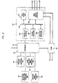
- Fig. 1 depicts a general block diagram of a speech processor that illustrates the invention.
- a speech pattern such as a spoken message is received by microphone transducer 101.
- the corresponding analog speech signal therefrom is band-limited and converted into a sequence of pulse samples in filter and sampler circuit 113 of prediction analyzer 110.
- the filtering may be arranged to remove frequency components of the speech signal above 4.0 KHz and the sampling may be at an 8.0 KHz rate as is well known in the art.
- the timing of the samples is controlled by sample clock SC from clock generator 103.
- Each sample from circuit 113 is transformed into an amplitude representative digital code in analog-to-digital converter 115.
- the speech samples from A/D converter 115 are delayed in delay 117 to allow time for the formation of speech parameter signals a k .
- the delayed samples are supplied to the input of prediction residual generator 118.
- the prediction residual- generator is responsive to the delayed speech samples and the prediction parameters a k to form a signal corresponding to the differences therebetween.
- the formation of the predictive parameters and the prediction residual signal for each frame shown in predictive analyzer 110 may be performed according to the arrangement disclosed in US-A-3,740,476 or in other arrangements well known in the art.
- Waveform 601 of Fig. 6 illustrates a typical speech pattern over a plurality of frames.
- Waveform 605 shows the prescribed format multipulse excitation signal for the speech pattern of waveform 601 in accordance with the arrangements described in GB ⁇ A ⁇ 2,110,906.
- the similarities between the excitation signal of the current frame and the excitation signals of preceding frames are removed from the prescribed format multipulse signal of waveform 605. Consequently, the pitch dependence of the multipulse signal is eliminated and the amplitude range of the multipulse signal is substantially reduced.
- the redundancy reduced multipulse signal of waveform 610 is obtained.
- a comparison between waveforms 605 and 610 illustrates the improvement that is achieved.
- Waveform 615 shows a replica of the pattern of waveform 601 obtained using the excitation signal of waveform 610, the redundancy parameter signals and the predictive parameter signals.
- the prediction residual signal d k and the predictive parameter signals a k for each successive frame are applied from circuit 110 (Fig. 1) to excitation signal forming circuit 120 at the beginning of the succeeding frame.
- Circuit 120 is operative to produce a redundancy reduced multielement excitation code EC having a predetermined number of bit positions for each frame and a redundancy parameter code y, M * for the frame.
- Each excitation code corresponds to a sequence of I ⁇ i ⁇ I pulses representative of the excitation function of the frame with multiframe redundancy removed to make it pitch insensitive.
- the amplitude ⁇ i and location m of each pulse within the frame is determined in the excitation signal forming circuit as well as the y and M * redundancy parameter signals so as to permit construction of a replica of the frame speech signal from the excitation signal when combined with the redundancy parameter signals, and the predictive parameter signals of the frame.
- the ⁇ i and m signals are encoded in coder 131.
- the y and M * signals are encoded in coder 155.
- the predictive residual signal d k and the predictive parameter signals a k of a frame are supplied to filter 121 via gates 122 and 124, respectively.
- frame clock signal FC opens gates 122 and 124 whereby the frame d k signal is applied to filter 121 and the frame a k signals are applied to filters 121 and 123.
- Filter 121 is adapted to modify signal d k so that the quantizing spectrum of the error signal is concentrated in the formant regions thereof. As disclosed in US-A-4,133,976, this filter arrangement is effective to mask the error in the high signal energy portions of the spectrum.
- the transfer function of filter 121 is expressed in z transform notation as: where and
- Predictive filter 123 receives the frame predictive parameter signals a k from computer 119 and an excitation signal v(n) corresponding to the prescribed format multipulse excitation signal EC from excitation signal former 145.
- Filter 123 has the transfer function of Equation 1.
- Filter 121 forms a weighted frame speech signal y responsive to the predictive residual d k while filter 123 generates a weighted predictive speech signal y responsive to the multipulse excitation signal being formed over the frame interval in multipulse signal generator 127.
- the output of filter 121 is where d k is the predictive residual signal from residual signal generator 118 and h n - k corresponds to the response of filter 121.
- the output of filter 123 is Signals y(n) and y(n) are applied to frame correlation signal generator 125 and the current frame predictive parameters a k are supplied to multiframe correlation signal generator 140.
- Multiframe correlation signal generator 140 is operative to form a multiframe correlation component signal yp(n) corresponding to the correlation of the speech pattern of the current frame to preceding frames, a signal z(n) corresponding to the contribution of preceding excitation of the current frame speech pattern, a current frame correlation parameter signal y, and a current frame correlation location signal M * .
- Signal z(n) is formed from its past values responsive to linear prediction parameter signals a k in accordance with A range of samples M min to M max extending over a plurality of preceding frames is defined.
- a signal representing the excitation or the preceding frame is produced from the proceeding frame prescribed format multipulse signal is produced.
- the multiframe correlated component of signal is obtained from signals y and zp(n, M * ).
- Signal y p (n) is supplied to frame correlation signal generator 125 which is operative to generate signal where responsive to signals y(n) from predictive filter 121, signal y(n) from predictive filter 123 and signal yp(n) from multiframe correlation signal generator 140.
- Signal C,q is representative of the weighted differences between signals y(n) and the combination of signals y(n) and y p (n).
- the effect of signal yp(n) in processor 125 is to remove long term redundancy from the weighted differences. The long term redundancy is generally related to the pitch predictable component of the speech pattern.
- the output of frame correlation generator 125 represents the maximum value of C iq over the current frame and its location q * .
- the signals ⁇ i and m i are formed iteratively until I such pulses are generated by feedback of the pulses through excitation signal former 145.
- the output of processor 125 has reduced redundancy so that the resulting excitation code obtained from multipulse signal generator 127 has a smaller dynamic range.
- the smaller dynamic range is illustrated by comparing waveforms 605 and 610 in Fig. 6. Additionally, the removal of the pitch related component from the multipulse excitation code renders the excitation substantially independent of the pitch of the input speech pattern. Consequently, a significant reduction in excitation code bit rate is achieved.
- Signal EC comprising the multipulse sequence ⁇ i , m is applied to multiplexor 135 via coder 131.
- the multipulse signal EC is also supplied to excitation signal former 145 in which an excitation signal v(n) corresponding to signal EC is produced.
- Signal v(n) modifies the signal formed in predictive filter 123 to adjust the excitation signal EC so that the differences between the weighted speech representative signal from filter 121 and the weighted artificial speech representative signal from filter 123 are reduced.
- Multipulse signal generator 127 receives the C ig signals from frame correlation signal generator 127, selects the C,q signal having the maximum absolute value and i th element of the coded signal as per Equation 14. The index i is incremented to i+1 and signal y(n) at the output of predictive filter 123 is modified. The process in accordance with Equations 4, and 6 is repeated to form element ⁇ i+1 , m i+1 . After the formation of element ⁇ i , m,., the signal having elements ⁇ i m 1 , ⁇ 2 m 2 , ..., ⁇ i m i is transferred to coder 131. As is well known in the art, coder 131 is operative to quantize the ⁇ i m i elements and to form a coded signal suitable for transmission to utilization device 148.
- Each of the filters 121 and 123 in Fig. 1 may comprise a recursive filter of the type described in aforementioned US-A-4,133,976.
- Each of generators 125,127, and 140 as well as excitation signal former 145 may comprise one of the processor arrangements well known in the art adapted to perform the processing required by Equations 4 and 6 such as the C.S.P., Inc. Macro Arithmetic Processor System 100 or other processor arrangements well known in the art. Alternatively, the aforementioned C.S.P. system may be used to accomplish the processing required in all of these generating and forming units.
- Generator 140 includes a read only memory that permanently stores a set of instructions to perform the functions of Equations 9-11.
- Processor 125 includes a read-only memory which permanently stores programmed instructions to control the C iq signal formation in accordance with Equation 4.
- Processor 127 includes a read-only memory which permanently stores programmed instructions to select the ⁇ i , m signal elements according to Equation 6 as is well known in the art. These read only memories may be selectively connected to a single processor arrangement of the type described as shown in Fig. 2.
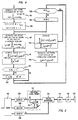
- Fig. 3 depicts a flow chart showing the operations of signal generators 125, 127, 140, and 145 for each time frame.
- the h k impulse response signals are generated in box 305 responsive to the frame predictive parameters a k in accordance with the transfer function of Equation 1. This occurs after receipt of the FC signal from clock 103 in Fig. 1 as per wait box 303.
- the generation of the multiframe correlation signal yp(n) and the multiframe correlation parameter signals y and M * is then performed in multiframe signal generator 140 as per box 306.
- the operations of box 306 are shown in greater detail in the flow chart of Fig. 4.
- the signal z(n) representative of the contribution of preceding excitation is generated (box 401) and stored in multiframe correlation signal generator 140 according to equation 1 responsive to the predictive parameter signals a k .
- Index M is set to Mmin and minimum error signal E is set to zero in box 405.
- the contribution of the preceding M samples to the excitation is generated as per Equation 6a and 6b.
- Signals y, M * , and yp(n) are stored in generator 440.
- the element index i and the excitation pulse location index q are initially set to 1 in box 307.
- signal C iq is formed as per box 309.
- the location index q is incremented in box 311 and the formation of the next location C iq signal is initiated.
- processor 127 After the C,q signal is formed for excitation signal element i in processor 125, processor 127 is activated.
- the q index in processor 127 is initially set to I in box 315 and the i index as well as the C iq signals formed in processor 125 are transferred to processor 127.
- Signal C iq * which represents the C iq signal having the maximum absolute value and its location q * are set to zero in box 317.
- the absolute values of the C,q signals are compared to signal C iq * and the maximum of these absolute values is stored as signal C iq * in the loop including boxes 319, 321, 323, and 325.
- box 327 is entered from box 325.
- the excitation code element location m is set to q * and the magnitude of the excitation code element ⁇ i is generated in accordance with Equation 6.
- the ⁇ i m i element is output to predictive filter 123 as per box 328 and index i is incremented as per box 329.
- signal v(n) for the frame is generated as per Equation 6a (box 340) and wait box 303 is reentered. Processors 125 and 127 are then placed in wait states until the FC frame clock pulse of the next frame.
- the excitation code in processor 127 is also supplied to coder 131.
- the coder is operative to transform the excitation code from processor 127 into a form suitable for use in network 140.
- the prediction parameters signals a k for the frame are supplied to an input of multiplexer 135 via delay 133 as signals a' k'
- the excitation coded signal ECS from coder 131 is applied to the other input of the multiplexer.
- the multiplexed excitation and predictive parameter codes for the frame are then sent to utilization device 148.
- the data processing circuit depicted in Fig. 2 provides an alternative arrangement to excitation signal forming circuit 120 of Fig. 1.
- the circuit of Fig. 2 yields the excitation code ⁇ i , m for each frame of the speech pattern as well as the redundancy parameter signals for the frame y, M * in response to the frame prediction residual signal d k and the frame prediction parameter signals a k in the circuit of Fig. 2 may comprise the previously mentioned C.S.P., Inc. Macro Arithmetic Processor System 100 or other processor arrangements well known in the art.
- processor 210 receives the predictive parameter signals a k and the prediction residual signals d k of each successive frame of the speech pattern from circuit 110 via store 218.
- the processor is operative to form the excitation code signal elements ⁇ 1 m 1 , ⁇ 2 , m 2 , ... ⁇ i , m i , and redundancy parameter signals y and M * under control of permanently stored instructions in predictive filter processing subroutine read-only memory 201, multiframe correlation processing read-only memory 212, frame correlation signal processing read-only memory 217, and excitation processing read-only memory 205.
- Processor 210 comprises common bus 225, data memory 230, central processor 240, arithmetic processor 250, controller interface 220 and input-output interface 260.
- central processor 240 is adapted to control the sequence of operations of the other units of processor 210 responsive to coded instructions from controller 215.
- Arithmetic processor 250 is adapted to perform the arithmetic processing on coded signals from data memory 230 responsive to control signals from central processor 240.
- Data memory 230 stores signals as directed by central processor 240 and provides such signals to arithmetic processor 250 and input-output interface 260.
- Controller interface 220 provides a communication link for the program instructions in the read-only memories 201, 205, 212, and 217 to central processor 240 via controller 215, and input-output interface 260 permits the d k and a k signal to be supplied to data memory 230 and supplies output signals ⁇ i , m, y and M * from the data memory to coders 131 and 155 in Fig. 1.
- FIG. 2 The operation of the circuit of Fig. 2 is illustrated in the flow charts of Figs. 3 and 4.
- box 305 in Fig. 3 is entered via box 303 after signal ST is obtained from clock signal generator 103 in Fig. 1.
- the predictive filter impulse response for signals y(n) and y(n) are formed as per box 305 in processors 240 and 250 under control of instructions from predictive filter processing ROM 201.
- Box 306 is then entered and the operations of the flow chart of Fig. 4 are carried out responsive to the instructions stored in ROM 212.
- These operations result in the formation of signals yp(n), y, and M * and have been described with respect to Fig. 1.
- Signals y and M * are made available at the output of input-output interface 260 and signal yp(nl is stored in data memory 230.
- controller 215 Upon completion of the operations of box 306, controller 215 connects frame correlation signal processing ROM 217 to central processor 240 via controller interface 220 and bus 225 so that the signals Cl,, C i q * , and q * are formed as per the operations of boxes 307 through 325 for the current value of excitation signal index i.
- Excitation signal processing ROM 205 is then connected to computer 210 by controller 215 and the signals ⁇ i and m are generated in boxes 327 through 333 as previously described with respect to Fig. 1.
- Signal v(n) is then produced for use in the next frame in box 340 as per equation 6a.
- controller 215 Upon completion of the operations of Fig. 3 for excitation signal ⁇ i , m" controller 215 places the circuit of Fig. 2 in a wait state as per box 303.
- the frame excitation code and the frame redundancy parameter signals from the processor of Fig. 2 are supplied via input-output interface 260 to coders 131 and 155 in Fig. 1 as is well known in the art. Coders 131 and 155 are operative as previously mentioned to quantize and format the excitation code and the redundancy parameter signals for application to utilization device 148.
- the a k prediction parameter signals of the frame are applied to one input of multiplexer 135 through delay 133 so that the frame excitation code from coder 131 may be appropriately multiplexed therewith.
- Utilization device 148 may be a communication system, the message store of a voice storage arrangement, or apparatus adapted to store a complete message or vocabulary of prescribed message units, e.g., words, phonemes, etc., for use in speech synthesizers. Whatever the message unit, the resulting sequence of frame codes from circuit 120 are forwarded via utilization device 148 to a speech synthesizer such as that shown in Fig. 5. The synthesizer, in turn, utilizes the frame excitation and redundancy parameter signal codes from circuit 120 as well as the frame predictive parameter codes to construct a replica of the speech pattern.
- Demultiplexer 502 in Fig. 5 separates the excitation code EC, the redundancy parameter codes y, M * , and the prediction parameters a k of each successive frame.
- the excitation coder after being decoded into an excitation pulse sequence in decoder 505, is applied to one input of summing circuit 511 in excitation signal former 510.
- the y, M * signals produced in decoder 506 are supplied to predictive filter 513 in excitation signal former 510.
- the predictive filter is operative as is well known in the art to combine the output of summer 511 with signals y and M * to generate the excitation pulse sequence of the frame.
- the transfer function of filter 513 is Signal M * operates to delay the redundancy reduced excitation pulse sequence and signal y operates to modify the magnitudes of the redundancy reduced excitation pulses so that the frame multi pulse excitation signal is reconstituted at the output of excitation signal former 510.
- the frame excitation pulse sequence from the output of excitation signal former 510 is applied to the excitation input of speech synthesizer filter 514.
- the a k predictive parameter signals decoded in decoder 508 are supplied to the parameter inputs of filter 514.
- Filter 514 is operative in response to the excitation and predictive parameter signals to form a digitally encoded replica of the frame speech signal as is well known in the art.
- D/A converter 516 is adapted to transform the coded replica into an analog signal which is passed through low-pass filter 518 and transformed into a speech pattern by transducer 520.
Landscapes
- Engineering & Computer Science (AREA)
- Computational Linguistics (AREA)
- Signal Processing (AREA)
- Health & Medical Sciences (AREA)
- Audiology, Speech & Language Pathology (AREA)
- Human Computer Interaction (AREA)
- Physics & Mathematics (AREA)
- Acoustics & Sound (AREA)
- Multimedia (AREA)
- Compression, Expansion, Code Conversion, And Decoders (AREA)
- Transmission Systems Not Characterized By The Medium Used For Transmission (AREA)
Abstract
Description
- This invention relates to speech analysis and more particularly to linear prediction speech pattern analyzers.
- Linear predictive coding (LPC) is used extensively in digital speech transmission, speech recognition and speech synthesis systems which must operate at low bit rates. The efficiency of LPC arrangements results from the encoding of the speech information rather than the speech signal itself. The speech information corresponds to the shape of the vocal tract and its excitation and, as is well known in the art, its bandwidth is substantially less than the bandwidth of the speech signal. The LPC coding technique partitions a speech pattern into a sequence of time frame intervals 5 to 20 milliseconds in duration. The speech signal is quasi-stationary during such time intervals and may be characterized by a relatively simple vocal tract model specified by a small number of parameters. For each time frame, a set of linear predictive parameters is generated which is representative of the spectral content of the speech pattern. Such parameters may be applied to a linear filter which models the human vocal tract along with signals representative of the vocal tract excitation to reconstruct a replica of the speech pattern. A system illustrative of such an arrangement is described in US-A-3,624,302.
- Vocal tract excitation for LPC speech coding and speech synthesis systems may take the form of pitch period signals for voiced speech, noise signals for unvoiced speech and a voiced-unvoiced signal corresponding to the type of speech in each successive LPC frame. While this excitation signal arrangement is sufficient to produce a replica of a speech pattern at relatively low bit rates, the resulting replica has limited intelligibility. A significant improvement in speech quality is obtained by using a predictive residual excitation signal corresponding to the difference between the speech pattern of a frame and a speech pattern produced in response to the LPC parameters of the frame. The predictive residual, however, is noise-like since it corresponds to the unpredicted portion of the speech pattern. Consequently, a very high bit rate is needed for its representation. US-A-3,631,520 discloses a speech coding system utilizing predictive residual excitation.
- In an arrangement disclosed in GB-A-2,110,906 that provides the high quality of predictive residual coding at a relatively low bit rate, a signal corresponding to the speech pattern for a frame is generated as well as a signal representative of its LPC parameters responsive speech pattern for the frame. A prescribed format multipulse signal is formed for each successive LPC frame responsive to the differences between the frame speech pattern signal and the frame LPC derived speech pattern signal. Unlike the predictive residual excitation whose bit rate is not controlled, the bit rate of the multipulse excitation signal may be selected to conform to prescribed transmission and storage requirements. In contrast to the predictive vocoder type arrangement, intelligibility is improved, partially voiced intervals are accurately encoded and classification of voiced and unvoiced speech intervals is eliminated.
- It has been observed that a multipulse excitation signal having approximately eight pulses per pitch period provides adequate speech quality at a bit rate substantially below that of the corresponding predictive resdiual. Speech pattern pitch, however, varies widely among individuals. More particularly, the pitch found in voices of children and adult females is generally much higher than the pitch for voices of adult males. As a result, the bit rate for multipulse excitation signals increases with voice pitch if high speech quality is to be maintained for all speakers. Thus, the bit rate in speech processing using multipulse excitation for adequate speech quality is a function of speaker pitch. It is an object of the invention to provide improved speech pattern coding with reduced excitation signal bit rate that is substantially independent of voice pitch.
- The foregoing object is achieved in the invention as set out in
apparatus claim 1 through removal of redundancy in the prescribed format multipulse excitation signal. A speech processor utilising signals produced in the apparatus ofclaim 1 is claimed in claim 3. A certain redundancy is found in all portions of speech patterns and is particularly evident in voiced portions thereof. Thus, signals indicative of excitation signal redundancy over several frames of speech may be coded and utilized to form a lower bit rate (redundancy reduced) excitation signal from the coded excitation signal. In forming a replica of the speech pattern, the redundancy indicative signals (the second excitation signal) are combined with the redundancy reduced (first) coded excitation signal to provide the appropriate excitation. Advantageously, the transmission facility bit rate and the coded speech storage requirements may be substantially reduced. -
- Fig. 1 depicts a block diagram of a speech coding arrangement illustrative of the invention;
- Fig. 2 depicts a block diagram of processing circuit arrangement that may be used in the arrangement of Fig. 1;
- Figs. 3 and 4 show flow charts that illustrate the operation of the processing circuit of Fig. 2;
- Fig. 5 shows a speech pattern synthesis arrangement that may be utilized as a decoder for the arrangement of Fig. 1; and
- Fig. 6 shows waveforms illustrating the speech processing according to the invention.
- Fig. 1 depicts a general block diagram of a speech processor that illustrates the invention. In Fig. 1, a speech pattern such as a spoken message is received by
microphone transducer 101. The corresponding analog speech signal therefrom is band-limited and converted into a sequence of pulse samples in filter andsampler circuit 113 ofprediction analyzer 110. The filtering may be arranged to remove frequency components of the speech signal above 4.0 KHz and the sampling may be at an 8.0 KHz rate as is well known in the art. The timing of the samples is controlled by sample clock SC fromclock generator 103. Each sample fromcircuit 113 is transformed into an amplitude representative digital code in analog-to-digital converter 115. The sequence of digitally coded speech samples is supplied topredictive parameter computer 119 which is operative, as is well known in the art, to partition the speech signals into 10 to 20 ms frame intervals and to generate a set of linear prediction coefficient signals ak, k=1, 2 ... p, representative of the predicted short time spectrum of the N»p speech samples of each frame. The speech samples from A/D converter 115 are delayed indelay 117 to allow time for the formation of speech parameter signals ak. The delayed samples are supplied to the input of predictionresidual generator 118. The prediction residual- generator, as is well known in the art, is responsive to the delayed speech samples and the prediction parameters ak to form a signal corresponding to the differences therebetween. The formation of the predictive parameters and the prediction residual signal for each frame shown inpredictive analyzer 110 may be performed according to the arrangement disclosed in US-A-3,740,476 or in other arrangements well known in the art. - While the predictive parameter signals ak form an efficient representation of the short time speech spectrum, the residual signal generally varies widely and rapidly over each interval and exhibits a high bit rate that is unsuitable for many applications.
Waveform 601 of Fig. 6 illustrates a typical speech pattern over a plurality of frames.Waveform 605 shows the prescribed format multipulse excitation signal for the speech pattern ofwaveform 601 in accordance with the arrangements described in GB―A―2,110,906. As a result of the invention, the similarities between the excitation signal of the current frame and the excitation signals of preceding frames are removed from the prescribed format multipulse signal ofwaveform 605. Consequently, the pitch dependence of the multipulse signal is eliminated and the amplitude range of the multipulse signal is substantially reduced. After processing in accordance with this invention, the redundancy reduced multipulse signal ofwaveform 610 is obtained. A comparison betweenwaveforms Waveform 615 shows a replica of the pattern ofwaveform 601 obtained using the excitation signal ofwaveform 610, the redundancy parameter signals and the predictive parameter signals. - The prediction residual signal dk and the predictive parameter signals ak for each successive frame are applied from circuit 110 (Fig. 1) to excitation
signal forming circuit 120 at the beginning of the succeeding frame.Circuit 120 is operative to produce a redundancy reduced multielement excitation code EC having a predetermined number of bit positions for each frame and a redundancy parameter code y, M* for the frame. Each excitation code corresponds to a sequence of I≤i≤I pulses representative of the excitation function of the frame with multiframe redundancy removed to make it pitch insensitive. The amplitude βi and location m of each pulse within the frame is determined in the excitation signal forming circuit as well as the y and M* redundancy parameter signals so as to permit construction of a replica of the frame speech signal from the excitation signal when combined with the redundancy parameter signals, and the predictive parameter signals of the frame. The βi and m signals are encoded incoder 131. The y and M* signals are encoded incoder 155. These excitation related signals are multiplexed with the delayed prediction parameter signals a'k of the frame inmultiplexer 135 to provide a coded digital signal corresponding to the frame speech pattern. - In excitation
signal forming circuit 120, the predictive residual signal dk and the predictive parameter signals ak of a frame are supplied to filter 121 viagates gates filters Filter 121 is adapted to modify signal dk so that the quantizing spectrum of the error signal is concentrated in the formant regions thereof. As disclosed in US-A-4,133,976, this filter arrangement is effective to mask the error in the high signal energy portions of the spectrum. - The transfer function of
filter 121 is expressed in z transform notation as:


-
Predictive filter 123 receives the frame predictive parameter signals ak fromcomputer 119 and an excitation signal v(n) corresponding to the prescribed format multipulse excitation signal EC from excitation signal former 145.Filter 123 has the transfer function ofEquation 1. Filter 121 forms a weighted frame speech signal y responsive to the predictive residual dk whilefilter 123 generates a weighted predictive speech signal y responsive to the multipulse excitation signal being formed over the frame interval inmultipulse signal generator 127. The output offilter 121 is
residual signal generator 118 and hn-k corresponds to the response offilter 121. The output offilter 123 is
correlation signal generator 125 and the current frame predictive parameters ak are supplied to multiframecorrelation signal generator 140. - Multiframe
correlation signal generator 140 is operative to form a multiframe correlation component signal yp(n) corresponding to the correlation of the speech pattern of the current frame to preceding frames, a signal z(n) corresponding to the contribution of preceding excitation of the current frame speech pattern, a current frame correlation parameter signal y, and a current frame correlation location signal M*. Signal z(n) is formed from its past values responsive to linear prediction parameter signals ak in accordance with


Equation 9 using the value of M* corresponding to the selected minimum signal E(y, M) as per Equation 10. - The multiframe correlated component of signal

- Signal yp(n) is supplied to frame
correlation signal generator 125 which is operative to generate signal

predictive filter 121, signal y(n) frompredictive filter 123 and signal yp(n) from multiframecorrelation signal generator 140. Signal C,q is representative of the weighted differences between signals y(n) and the combination of signals y(n) and yp(n). The effect of signal yp(n) inprocessor 125 is to remove long term redundancy from the weighted differences. The long term redundancy is generally related to the pitch predictable component of the speech pattern. The output offrame correlation generator 125 represents the maximum value of Ciq over the current frame and its location q*.Generator 127 produces a pulse of magnitude
- In accordance with the invention, the output of
processor 125 has reduced redundancy so that the resulting excitation code obtained frommultipulse signal generator 127 has a smaller dynamic range. The smaller dynamic range is illustrated by comparingwaveforms - Signal EC comprising the multipulse sequence βi, m is applied to
multiplexor 135 viacoder 131. The multipulse signal EC is also supplied to excitation signal former 145 in which an excitation signal v(n) corresponding to signal EC is produced. Signal v(n) modifies the signal formed inpredictive filter 123 to adjust the excitation signal EC so that the differences between the weighted speech representative signal fromfilter 121 and the weighted artificial speech representative signal fromfilter 123 are reduced. -
Multipulse signal generator 127 receives the Cig signals from framecorrelation signal generator 127, selects the C,q signal having the maximum absolute value and ith element of the coded signal as per Equation 14. The index i is incremented to i+1 and signal y(n) at the output ofpredictive filter 123 is modified. The process in accordance withEquations 4, and 6 is repeated to form element βi+1, mi+1. After the formation of element βi, m,., the signal having elements βim1, β2m2, ..., βimi is transferred tocoder 131. As is well known in the art,coder 131 is operative to quantize the βimi elements and to form a coded signal suitable for transmission toutilization device 148. - Each of the
filters Equations 4 and 6 such as the C.S.P., Inc. Macro Arithmetic Processor System 100 or other processor arrangements well known in the art. Alternatively, the aforementioned C.S.P. system may be used to accomplish the processing required in all of these generating and forming units.Generator 140 includes a read only memory that permanently stores a set of instructions to perform the functions of Equations 9-11.Processor 125 includes a read-only memory which permanently stores programmed instructions to control the Ciq signal formation in accordance withEquation 4.Processor 127 includes a read-only memory which permanently stores programmed instructions to select the βi, m signal elements according to Equation 6 as is well known in the art. These read only memories may be selectively connected to a single processor arrangement of the type described as shown in Fig. 2. - Fig. 3 depicts a flow chart showing the operations of
signal generators box 305 responsive to the frame predictive parameters ak in accordance with the transfer function ofEquation 1. This occurs after receipt of the FC signal fromclock 103 in Fig. 1 as perwait box 303. The generation of the multiframe correlation signal yp(n) and the multiframe correlation parameter signals y and M* is then performed inmultiframe signal generator 140 as perbox 306. The operations ofbox 306 are shown in greater detail in the flow chart of Fig. 4. - Referring to Figs. 1 and 4, the signal z(n) representative of the contribution of preceding excitation is generated (box 401) and stored in multiframe
correlation signal generator 140 according toequation 1 responsive to the predictive parameter signals ak. Index M is set to Mmin and minimum error signal E is set to zero inbox 405. Theloop including boxes box 410, the contribution of the preceding M samples to the excitation is generated as per Equation 6a and 6b. The error signal for the current frame is generated in box 415 and compared to the minimum error signal E* indecision box 420. If the current error signal is smaller than E*, E* is replaced (box 420), its location M becomes M* (box 425) anddecision box 430 is reached. Otherwise,decision box 430 is entered directly frombox 420. Sample index M is incremented (box 435) and the loop frombox 410 tobox 435 is iterated until sample Mmax is detected inbox 430. When M=Mmax, correlation parameter y for the current frame is generated (box 440) in accordance withEquation 9 using sample M* and the multiframe correlation signal yp(n) is generated inbox 445. Signals y, M*, and yp(n) are stored ingenerator 440. The element index i and the excitation pulse location index q are initially set to 1 inbox 307. Upon receipt of signals y(n) and y(n) frompredictive filters box 309. The location index q is incremented inbox 311 and the formation of the next location Ciq signal is initiated. - After the C,q signal is formed for excitation signal element i in
processor 125,processor 127 is activated. The q index inprocessor 127 is initially set to I inbox 315 and the i index as well as the Ciq signals formed inprocessor 125 are transferred toprocessor 127. Signal Ciq* which represents the Ciq signal having the maximum absolute value and its location q* are set to zero inbox 317. The absolute values of the C,q signals are compared to signal Ciq* and the maximum of these absolute values is stored as signal Ciq* in theloop including boxes - After the Ciq signal from
processor 125 has been processed,box 327 is entered frombox 325. The excitation code element location m is set to q* and the magnitude of the excitation code element βi is generated in accordance with Equation 6. The βimi element is output topredictive filter 123 as perbox 328 and index i is incremented as perbox 329. Upon formation of the βimi element of the frame, signal v(n) for the frame is generated as per Equation 6a (box 340) and waitbox 303 is reentered.Processors - The excitation code in
processor 127 is also supplied tocoder 131. The coder is operative to transform the excitation code fromprocessor 127 into a form suitable for use innetwork 140. The prediction parameters signals ak for the frame are supplied to an input ofmultiplexer 135 viadelay 133 as signals a'k' The excitation coded signal ECS fromcoder 131 is applied to the other input of the multiplexer. The multiplexed excitation and predictive parameter codes for the frame are then sent toutilization device 148. - The data processing circuit depicted in Fig. 2 provides an alternative arrangement to excitation
signal forming circuit 120 of Fig. 1. The circuit of Fig. 2 yields the excitation code βi, m for each frame of the speech pattern as well as the redundancy parameter signals for the frame y, M* in response to the frame prediction residual signal dk and the frame prediction parameter signals ak in the circuit of Fig. 2 may comprise the previously mentioned C.S.P., Inc. Macro Arithmetic Processor System 100 or other processor arrangements well known in the art. - Referring to Fig. 2,
processor 210 receives the predictive parameter signals ak and the prediction residual signals dk of each successive frame of the speech pattern fromcircuit 110 viastore 218. The processor is operative to form the excitation code signal elements β1m1, β2, m2, ... βi, mi, and redundancy parameter signals y and M* under control of permanently stored instructions in predictive filter processing subroutine read-only memory 201, multiframe correlation processing read-only memory 212, frame correlation signal processing read-only memory 217, and excitation processing read-only memory 205. -
Processor 210 comprisescommon bus 225,data memory 230,central processor 240,arithmetic processor 250,controller interface 220 and input-output interface 260. As is well known in the art,central processor 240 is adapted to control the sequence of operations of the other units ofprocessor 210 responsive to coded instructions fromcontroller 215.Arithmetic processor 250 is adapted to perform the arithmetic processing on coded signals fromdata memory 230 responsive to control signals fromcentral processor 240.Data memory 230 stores signals as directed bycentral processor 240 and provides such signals toarithmetic processor 250 and input-output interface 260.Controller interface 220 provides a communication link for the program instructions in the read-only memories central processor 240 viacontroller 215, and input-output interface 260 permits the dk and ak signal to be supplied todata memory 230 and supplies output signals βi, m, y and M* from the data memory tocoders - The operation of the circuit of Fig. 2 is illustrated in the flow charts of Figs. 3 and 4. At the start of the speech signal,
box 305 in Fig. 3 is entered viabox 303 after signal ST is obtained fromclock signal generator 103 in Fig. 1. The predictive filter impulse response for signals y(n) and y(n) are formed as perbox 305 inprocessors filter processing ROM 201.Box 306 is then entered and the operations of the flow chart of Fig. 4 are carried out responsive to the instructions stored inROM 212. These operations result in the formation of signals yp(n), y, and M* and have been described with respect to Fig. 1. Signals y and M* are made available at the output of input-output interface 260 and signal yp(nl is stored indata memory 230. - Upon completion of the operations of
box 306,controller 215 connects frame correlationsignal processing ROM 217 tocentral processor 240 viacontroller interface 220 andbus 225 so that the signals Cl,, Ciq*, and q* are formed as per the operations ofboxes 307 through 325 for the current value of excitation signal index i. Excitationsignal processing ROM 205 is then connected tocomputer 210 bycontroller 215 and the signals βi and m are generated inboxes 327 through 333 as previously described with respect to Fig. 1. Signal v(n) is then produced for use in the next frame inbox 340 as per equation 6a. The excitation signals are generated in serial fashion for i=1, 2, ... , I in each frame. Upon completion of the operations of Fig. 3 for excitation signal βi, m"controller 215 places the circuit of Fig. 2 in a wait state as perbox 303. - The frame excitation code and the frame redundancy parameter signals from the processor of Fig. 2 are supplied via input-
output interface 260 tocoders Coders utilization device 148. The ak prediction parameter signals of the frame are applied to one input ofmultiplexer 135 throughdelay 133 so that the frame excitation code fromcoder 131 may be appropriately multiplexed therewith. -
Utilization device 148 may be a communication system, the message store of a voice storage arrangement, or apparatus adapted to store a complete message or vocabulary of prescribed message units, e.g., words, phonemes, etc., for use in speech synthesizers. Whatever the message unit, the resulting sequence of frame codes fromcircuit 120 are forwarded viautilization device 148 to a speech synthesizer such as that shown in Fig. 5. The synthesizer, in turn, utilizes the frame excitation and redundancy parameter signal codes fromcircuit 120 as well as the frame predictive parameter codes to construct a replica of the speech pattern. -
Demultiplexer 502 in Fig. 5 separates the excitation code EC, the redundancy parameter codes y, M*, and the prediction parameters ak of each successive frame. The excitation coder, after being decoded into an excitation pulse sequence indecoder 505, is applied to one input of summingcircuit 511 in excitation signal former 510. The y, M* signals produced indecoder 506 are supplied to predictive filter 513 in excitation signal former 510. The predictive filter is operative as is well known in the art to combine the output ofsummer 511 with signals y and M* to generate the excitation pulse sequence of the frame. The transfer function of filter 513 is
- The frame excitation pulse sequence from the output of excitation signal former 510 is applied to the excitation input of
speech synthesizer filter 514. The ak predictive parameter signals decoded indecoder 508 are supplied to the parameter inputs offilter 514.Filter 514 is operative in response to the excitation and predictive parameter signals to form a digitally encoded replica of the frame speech signal as is well known in the art. D/A converter 516 is adapted to transform the coded replica into an analog signal which is passed through low-pass filter 518 and transformed into a speech pattern bytransducer 520.
Claims (3)
Applications Claiming Priority (2)
| Application Number | Priority Date | Filing Date | Title |
|---|---|---|---|
| US06/590,228 US4701954A (en) | 1984-03-16 | 1984-03-16 | Multipulse LPC speech processing arrangement |
| US590228 | 1984-03-16 |
Publications (2)
| Publication Number | Publication Date |
|---|---|
| EP0175752A1 EP0175752A1 (en) | 1986-04-02 |
| EP0175752B1 true EP0175752B1 (en) | 1990-01-24 |
Family
ID=24361379
Family Applications (1)
| Application Number | Title | Priority Date | Filing Date |
|---|---|---|---|
| EP85901727A Expired EP0175752B1 (en) | 1984-03-16 | 1985-03-08 | Multipulse lpc speech processing arrangement |
Country Status (6)
| Country | Link |
|---|---|
| US (1) | US4701954A (en) |
| EP (1) | EP0175752B1 (en) |
| JP (1) | JPH0668680B2 (en) |
| CA (1) | CA1222568A (en) |
| DE (1) | DE3575624D1 (en) |
| WO (1) | WO1985004276A1 (en) |
Families Citing this family (34)
| Publication number | Priority date | Publication date | Assignee | Title |
|---|---|---|---|---|
| JPS60225200A (en) * | 1984-04-23 | 1985-11-09 | 日本電気株式会社 | Voice encoder |
| JPS60239798A (en) * | 1984-05-14 | 1985-11-28 | 日本電気株式会社 | Voice waveform coder/decoder |
| CA1255802A (en) * | 1984-07-05 | 1989-06-13 | Kazunori Ozawa | Low bit-rate pattern encoding and decoding with a reduced number of excitation pulses |
| IT1180126B (en) * | 1984-11-13 | 1987-09-23 | Cselt Centro Studi Lab Telecom | PROCEDURE AND DEVICE FOR CODING AND DECODING THE VOICE SIGNAL BY VECTOR QUANTIZATION TECHNIQUES |
| US4944013A (en) * | 1985-04-03 | 1990-07-24 | British Telecommunications Public Limited Company | Multi-pulse speech coder |
| US4912764A (en) * | 1985-08-28 | 1990-03-27 | American Telephone And Telegraph Company, At&T Bell Laboratories | Digital speech coder with different excitation types |
| US4890328A (en) * | 1985-08-28 | 1989-12-26 | American Telephone And Telegraph Company | Voice synthesis utilizing multi-level filter excitation |
| JPH0636159B2 (en) * | 1985-12-18 | 1994-05-11 | 日本電気株式会社 | Pitch detector |
| US4827517A (en) * | 1985-12-26 | 1989-05-02 | American Telephone And Telegraph Company, At&T Bell Laboratories | Digital speech processor using arbitrary excitation coding |
| USRE34247E (en) * | 1985-12-26 | 1993-05-11 | At&T Bell Laboratories | Digital speech processor using arbitrary excitation coding |
| CA1323934C (en) * | 1986-04-15 | 1993-11-02 | Tetsu Taguchi | Speech processing apparatus |
| US4771465A (en) * | 1986-09-11 | 1988-09-13 | American Telephone And Telegraph Company, At&T Bell Laboratories | Digital speech sinusoidal vocoder with transmission of only subset of harmonics |
| US4797926A (en) * | 1986-09-11 | 1989-01-10 | American Telephone And Telegraph Company, At&T Bell Laboratories | Digital speech vocoder |
| JPH0738118B2 (en) * | 1987-02-04 | 1995-04-26 | 日本電気株式会社 | Multi-pulse encoder |
| US4817157A (en) * | 1988-01-07 | 1989-03-28 | Motorola, Inc. | Digital speech coder having improved vector excitation source |
| US4896361A (en) * | 1988-01-07 | 1990-01-23 | Motorola, Inc. | Digital speech coder having improved vector excitation source |
| US4896346A (en) * | 1988-11-21 | 1990-01-23 | American Telephone And Telegraph Company, At&T Bell Laboratories | Password controlled switching system |
| JP2903533B2 (en) * | 1989-03-22 | 1999-06-07 | 日本電気株式会社 | Audio coding method |
| JPH0398318A (en) * | 1989-09-11 | 1991-04-23 | Fujitsu Ltd | Voice coding system |
| NL8902347A (en) * | 1989-09-20 | 1991-04-16 | Nederland Ptt | METHOD FOR CODING AN ANALOGUE SIGNAL WITHIN A CURRENT TIME INTERVAL, CONVERTING ANALOGUE SIGNAL IN CONTROL CODES USABLE FOR COMPOSING AN ANALOGUE SIGNAL SYNTHESIGNAL. |
| US5235669A (en) * | 1990-06-29 | 1993-08-10 | At&T Laboratories | Low-delay code-excited linear-predictive coding of wideband speech at 32 kbits/sec |
| FI98104C (en) * | 1991-05-20 | 1997-04-10 | Nokia Mobile Phones Ltd | Procedures for generating an excitation vector and digital speech encoder |
| US5680506A (en) * | 1994-12-29 | 1997-10-21 | Lucent Technologies Inc. | Apparatus and method for speech signal analysis |
| SE508788C2 (en) * | 1995-04-12 | 1998-11-02 | Ericsson Telefon Ab L M | Method of determining the positions within a speech frame for excitation pulses |
| US5822724A (en) | 1995-06-14 | 1998-10-13 | Nahumi; Dror | Optimized pulse location in codebook searching techniques for speech processing |
| US5704003A (en) * | 1995-09-19 | 1997-12-30 | Lucent Technologies Inc. | RCELP coder |
| KR100217372B1 (en) * | 1996-06-24 | 1999-09-01 | 윤종용 | Pitch extracting method of voice processing apparatus |
| JP3930612B2 (en) * | 1997-08-07 | 2007-06-13 | 本田技研工業株式会社 | Connecting rod tightening device |
| US5963897A (en) * | 1998-02-27 | 1999-10-05 | Lernout & Hauspie Speech Products N.V. | Apparatus and method for hybrid excited linear prediction speech encoding |
| US6510407B1 (en) | 1999-10-19 | 2003-01-21 | Atmel Corporation | Method and apparatus for variable rate coding of speech |
| US7206739B2 (en) * | 2001-05-23 | 2007-04-17 | Samsung Electronics Co., Ltd. | Excitation codebook search method in a speech coding system |
| US7164672B1 (en) | 2002-03-29 | 2007-01-16 | At&T Corp. | Method and apparatus for QoS improvement with packet voice transmission over wireless LANs |
| US20040064314A1 (en) * | 2002-09-27 | 2004-04-01 | Aubert Nicolas De Saint | Methods and apparatus for speech end-point detection |
| US20090248404A1 (en) * | 2006-07-12 | 2009-10-01 | Panasonic Corporation | Lost frame compensating method, audio encoding apparatus and audio decoding apparatus |
Family Cites Families (9)
| Publication number | Priority date | Publication date | Assignee | Title |
|---|---|---|---|---|
| US3631520A (en) * | 1968-08-19 | 1971-12-28 | Bell Telephone Labor Inc | Predictive coding of speech signals |
| US3582546A (en) * | 1969-06-13 | 1971-06-01 | Bell Telephone Labor Inc | Redundancy reduction system for use with a signal having frame intervals |
| US3624302A (en) * | 1969-10-29 | 1971-11-30 | Bell Telephone Labor Inc | Speech analysis and synthesis by the use of the linear prediction of a speech wave |
| US3750024A (en) * | 1971-06-16 | 1973-07-31 | Itt Corp Nutley | Narrow band digital speech communication system |
| US4022974A (en) * | 1976-06-03 | 1977-05-10 | Bell Telephone Laboratories, Incorporated | Adaptive linear prediction speech synthesizer |
| US4130729A (en) * | 1977-09-19 | 1978-12-19 | Scitronix Corporation | Compressed speech system |
| US4133976A (en) * | 1978-04-07 | 1979-01-09 | Bell Telephone Laboratories, Incorporated | Predictive speech signal coding with reduced noise effects |
| US4304964A (en) * | 1978-04-28 | 1981-12-08 | Texas Instruments Incorporated | Variable frame length data converter for a speech synthesis circuit |
| US4472832A (en) * | 1981-12-01 | 1984-09-18 | At&T Bell Laboratories | Digital speech coder |
-
1984
- 1984-03-16 US US06/590,228 patent/US4701954A/en not_active Expired - Lifetime
-
1985
- 1985-03-08 WO PCT/US1985/000396 patent/WO1985004276A1/en active IP Right Grant
- 1985-03-08 EP EP85901727A patent/EP0175752B1/en not_active Expired
- 1985-03-08 JP JP60501146A patent/JPH0668680B2/en not_active Expired - Lifetime
- 1985-03-08 DE DE8585901727T patent/DE3575624D1/en not_active Expired - Lifetime
- 1985-03-15 CA CA000476644A patent/CA1222568A/en not_active Expired
Also Published As
| Publication number | Publication date |
|---|---|
| DE3575624D1 (en) | 1990-03-01 |
| JPH0668680B2 (en) | 1994-08-31 |
| CA1222568A (en) | 1987-06-02 |
| EP0175752A1 (en) | 1986-04-02 |
| JPS61501474A (en) | 1986-07-17 |
| US4701954A (en) | 1987-10-20 |
| WO1985004276A1 (en) | 1985-09-26 |
Similar Documents
| Publication | Publication Date | Title |
|---|---|---|
| EP0175752B1 (en) | Multipulse lpc speech processing arrangement | |
| US4472832A (en) | Digital speech coder | |
| US4220819A (en) | Residual excited predictive speech coding system | |
| US4709390A (en) | Speech message code modifying arrangement | |
| USRE32580E (en) | Digital speech coder | |
| US5018200A (en) | Communication system capable of improving a speech quality by classifying speech signals | |
| US6041297A (en) | Vocoder for coding speech by using a correlation between spectral magnitudes and candidate excitations | |
| US6345248B1 (en) | Low bit-rate speech coder using adaptive open-loop subframe pitch lag estimation and vector quantization | |
| US5457783A (en) | Adaptive speech coder having code excited linear prediction | |
| EP0342687B1 (en) | Coded speech communication system having code books for synthesizing small-amplitude components | |
| EP0232456A1 (en) | Digital speech processor using arbitrary excitation coding | |
| US4945565A (en) | Low bit-rate pattern encoding and decoding with a reduced number of excitation pulses | |
| US5027405A (en) | Communication system capable of improving a speech quality by a pair of pulse producing units | |
| Singhal et al. | Optimizing LPC filter parameters for multi-pulse excitation | |
| JPH09258795A (en) | Digital filter and sound coding/decoding device | |
| EP0361432B1 (en) | Method of and device for speech signal coding and decoding by means of a multipulse excitation | |
| USRE34247E (en) | Digital speech processor using arbitrary excitation coding | |
| Wong | On understanding the quality problems of LPC speech | |
| EP0537948B1 (en) | Method and apparatus for smoothing pitch-cycle waveforms | |
| JP2648138B2 (en) | How to compress audio patterns | |
| GB2205469A (en) | Multi-pulse type coding system | |
| Morikawa et al. | A speech analysis-synthesis system based on the ARMA model and its evaluation | |
| WO1995006310A1 (en) | Adaptive speech coder having code excited linear prediction |
Legal Events
| Date | Code | Title | Description |
|---|---|---|---|
| PUAI | Public reference made under article 153(3) epc to a published international application that has entered the european phase |
Free format text: ORIGINAL CODE: 0009012 |
|
| AK | Designated contracting states |
Kind code of ref document: A1 Designated state(s): BE DE FR GB NL SE |
|
| 17P | Request for examination filed |
Effective date: 19860303 |
|
| 17Q | First examination report despatched |
Effective date: 19871102 |
|
| GRAA | (expected) grant |
Free format text: ORIGINAL CODE: 0009210 |
|
| AK | Designated contracting states |
Kind code of ref document: B1 Designated state(s): BE DE FR GB NL SE |
|
| REF | Corresponds to: |
Ref document number: 3575624 Country of ref document: DE Date of ref document: 19900301 |
|
| ET | Fr: translation filed | ||
| PLBE | No opposition filed within time limit |
Free format text: ORIGINAL CODE: 0009261 |
|
| STAA | Information on the status of an ep patent application or granted ep patent |
Free format text: STATUS: NO OPPOSITION FILED WITHIN TIME LIMIT |
|
| 26N | No opposition filed | ||
| EAL | Se: european patent in force in sweden |
Ref document number: 85901727.9 |
|
| REG | Reference to a national code |
Ref country code: GB Ref legal event code: IF02 |
|
| PGFP | Annual fee paid to national office [announced via postgrant information from national office to epo] |
Ref country code: BE Payment date: 20020114 Year of fee payment: 18 |
|
| PG25 | Lapsed in a contracting state [announced via postgrant information from national office to epo] |
Ref country code: BE Free format text: LAPSE BECAUSE OF NON-PAYMENT OF DUE FEES Effective date: 20030331 |
|
| BERE | Be: lapsed |
Owner name: *AMERICAN TELEPHONE AND TELEGRAPH CY Effective date: 20030331 |
|
| PGFP | Annual fee paid to national office [announced via postgrant information from national office to epo] |
Ref country code: SE Payment date: 20031222 Year of fee payment: 20 |
|
| PGFP | Annual fee paid to national office [announced via postgrant information from national office to epo] |
Ref country code: GB Payment date: 20040220 Year of fee payment: 20 |
|
| PGFP | Annual fee paid to national office [announced via postgrant information from national office to epo] |
Ref country code: NL Payment date: 20040223 Year of fee payment: 20 Ref country code: FR Payment date: 20040223 Year of fee payment: 20 |
|
| PGFP | Annual fee paid to national office [announced via postgrant information from national office to epo] |
Ref country code: DE Payment date: 20040304 Year of fee payment: 20 |
|
| PG25 | Lapsed in a contracting state [announced via postgrant information from national office to epo] |
Ref country code: GB Free format text: LAPSE BECAUSE OF EXPIRATION OF PROTECTION Effective date: 20050307 |
|
| PG25 | Lapsed in a contracting state [announced via postgrant information from national office to epo] |
Ref country code: NL Free format text: LAPSE BECAUSE OF EXPIRATION OF PROTECTION Effective date: 20050308 |
|
| REG | Reference to a national code |
Ref country code: GB Ref legal event code: PE20 |
|
| NLV7 | Nl: ceased due to reaching the maximum lifetime of a patent |
Effective date: 20050308 |
|
| EUG | Se: european patent has lapsed |