EP0342605A2 - Film magazine assembling system - Google Patents
Film magazine assembling system Download PDFInfo
- Publication number
- EP0342605A2 EP0342605A2 EP89108776A EP89108776A EP0342605A2 EP 0342605 A2 EP0342605 A2 EP 0342605A2 EP 89108776 A EP89108776 A EP 89108776A EP 89108776 A EP89108776 A EP 89108776A EP 0342605 A2 EP0342605 A2 EP 0342605A2
- Authority
- EP
- European Patent Office
- Prior art keywords
- chuck
- barrel plate
- magazine
- magazine casing
- casing assembling
- Prior art date
- Legal status (The legal status is an assumption and is not a legal conclusion. Google has not performed a legal analysis and makes no representation as to the accuracy of the status listed.)
- Granted
Links
Images

Classifications
-
- G—PHYSICS
- G03—PHOTOGRAPHY; CINEMATOGRAPHY; ANALOGOUS TECHNIQUES USING WAVES OTHER THAN OPTICAL WAVES; ELECTROGRAPHY; HOLOGRAPHY
- G03B—APPARATUS OR ARRANGEMENTS FOR TAKING PHOTOGRAPHS OR FOR PROJECTING OR VIEWING THEM; APPARATUS OR ARRANGEMENTS EMPLOYING ANALOGOUS TECHNIQUES USING WAVES OTHER THAN OPTICAL WAVES; ACCESSORIES THEREFOR
- G03B17/00—Details of cameras or camera bodies; Accessories therefor
- G03B17/26—Holders for containing light sensitive material and adapted to be inserted within the camera
-
- Y—GENERAL TAGGING OF NEW TECHNOLOGICAL DEVELOPMENTS; GENERAL TAGGING OF CROSS-SECTIONAL TECHNOLOGIES SPANNING OVER SEVERAL SECTIONS OF THE IPC; TECHNICAL SUBJECTS COVERED BY FORMER USPC CROSS-REFERENCE ART COLLECTIONS [XRACs] AND DIGESTS
- Y10—TECHNICAL SUBJECTS COVERED BY FORMER USPC
- Y10T—TECHNICAL SUBJECTS COVERED BY FORMER US CLASSIFICATION
- Y10T29/00—Metal working
- Y10T29/53—Means to assemble or disassemble
- Y10T29/53313—Means to interrelatedly feed plural work parts from plural sources without manual intervention
- Y10T29/53322—Means to assemble container
-
- Y—GENERAL TAGGING OF NEW TECHNOLOGICAL DEVELOPMENTS; GENERAL TAGGING OF CROSS-SECTIONAL TECHNOLOGIES SPANNING OVER SEVERAL SECTIONS OF THE IPC; TECHNICAL SUBJECTS COVERED BY FORMER USPC CROSS-REFERENCE ART COLLECTIONS [XRACs] AND DIGESTS
- Y10—TECHNICAL SUBJECTS COVERED BY FORMER USPC
- Y10T—TECHNICAL SUBJECTS COVERED BY FORMER US CLASSIFICATION
- Y10T29/00—Metal working
- Y10T29/53—Means to assemble or disassemble
- Y10T29/53465—Film or tape cartridge
-
- Y—GENERAL TAGGING OF NEW TECHNOLOGICAL DEVELOPMENTS; GENERAL TAGGING OF CROSS-SECTIONAL TECHNOLOGIES SPANNING OVER SEVERAL SECTIONS OF THE IPC; TECHNICAL SUBJECTS COVERED BY FORMER USPC CROSS-REFERENCE ART COLLECTIONS [XRACs] AND DIGESTS
- Y10—TECHNICAL SUBJECTS COVERED BY FORMER USPC
- Y10T—TECHNICAL SUBJECTS COVERED BY FORMER US CLASSIFICATION
- Y10T29/00—Metal working
- Y10T29/53—Means to assemble or disassemble
- Y10T29/53478—Means to assemble or disassemble with magazine supply
- Y10T29/53522—Means to fasten by deforming
Definitions
- This invention relates to a film magazine assembling system which loads a film assembly (a roll film with a spool around which it is wound) into a film magazine casing barrel plate and caps opposite ends of the film magazine casing barrel plate in the manufacturing process of 16mm film magazine, 35mm film magazine or the like.
- the film magazine casing barrel plate is sent to a film assembly feeding station with one end capped and the other end opened, and a film assembly is loaded into the film magazine casing barrel plate. Thereafter, the barrel plate carrying therein the film assembly is sent to a capping station where the other end of the barrel plate is capped.
- the barrel plate with only one end capped is hard to handle and is apt to cause trouble.
- the orientation of the barrel plate can change during transfer to the film assembly feeding station or from the film assembly feeding station to the capping station. Further, when the film assembly is loaded into the barrel plate, the film can be folded.
- the barrel plate in such a state is carried by a pallet mounted on an endless chain and is transferred to the film assembly feeding station or the like.
- the pallet is mounted on the chain, it is difficult to accurately position the barrel plate carried by the pallet.
- the primary object of the present invention is to provide a film magazine assembling system which can transfer a part rolled state film magazine casing barrel plate and position it with a high accuracy so that loading of a film assembly into the barrel plate and capping of the barrel plate can be performed easily and accurately.
- Another object of the present invention is to provide a capping system and a magazine casing assembling chuck which are particularly suitable for use in the film magazine assembling system.
- a film magazine assembling system comprising a plurality of two-part magazine casing assembling chucks, each comprising a pair of chuck members the inner surfaces of which are a part of a cylindrical surface in shape and which can be selectively brought into a closed state where the chuck members are mated with each other so that the inner surfaces thereof substantially form a cylindrical surface and into an open state where one of the side edges of one of the chuck members parallel to the longitudinal axis of the cylindrical surface is spaced from the mating edge of the other chuck member, an indexing means which is rotatable about a substantially horizontal rotational axis and supports the magazine casing assembling chucks at regular angular intervals about the rotational axis so that the longitudinal axis of said cylindrical surface is held horizontal, an indexing means driving means which intermittently rotates the indexing means by an angle equal to the angular interval, thereby successively stopping each magazine casing assembling chuck at a plurality of stations, a
- the barrel plate can be accurately positioned since it is held by a pair of chuck members which substantially form a cylindrical surface when mated with each other.
- the present invention further provides a two-part magazine casing assembling chuck which is particularly advantageous in accurately positioning the barrel plate. That is, in accordance with another aspect of the present invention, there is provided a two-part film magazine casing assembling chuck for assembling a film magazine casing having a barrel provided with a magazine slit comprising a pair of chuck members the inner surfaces of which are a part of a cylindrical surface in shape and which can be selectively brought into a closed state where the chuck members are mated with each other so that the inner surfaces thereof substantially form a cylindrical surface and into an open state where one of the side edges of one of the chuck members parallel to the longitudinal axis of the cylindrical surface is spaced from the mating edge of the other chuck member, an edge portion with which a turned edge portion of a barrel plate for forming the magazine slit is to be engaged being provided on said one side edges of said one chuck member, a barrel plate pushing member which resiliently pushes the barrel plate positioned between the chuck members toward said one chuck member being
- the barrel plate When the barrel plate is resiliently pressed against one of the chuck members and the turned edge portion of the barrel plate is brought into engagement with the edge portion of the chuck member, the barrel plate can be positioned with a very high accuracy.
- a capping system for mounting caps on respective ends of a barrel plate of a film magazine which has been fed with a film assembly consisting of a spool and a roll film wound around the spool and is held so that the spool is substantially horizontally positioned, comprising a cap feeding means which positions a pair of caps to be opposed to the respective ends of the barrel plate, each cap having a boss hole to be engaged with an end of the spool, a pair of guide shafts which are opposed to the respective ends of the barrel plate and is adapted to be moved toward the barrel plate through the boss holes of the caps so that the tip portions of the respective guide shafts are fitted in the respective ends of the spool, a pair of cap pushing means which respectively pushes the caps along the guide shafts towards the ends of the barrel plate so as to be engaged with the respective ends of the barrel plate, and a pair of cap caulking means each of which comprises a plurality of caulking claws which are disposed about
- the capping operation is carried out from each side of the barrel plate in the capping system, two caps are mounted on the respective ends of the barrel plate at one time, thereby increasing the working efficiency. Further, since the caps are slid on the guide shafts when they are fitted on the barrel plate, they cannot fall or incline during the capping operation. Further, since the caps are correctly coaxially located with respect to the spool by the guide shaft, the capping operation can be performed with a high accuracy.
- the capping system is provided with a confining member which grasps the barrel plate from outside.
- a confining member which grasps the barrel plate from outside.
- a film magazine assembling system in accordance with an embodiment of the present invention includes an indexing member 10 which is in the form of a rotary plate rotatable about a rotational shaft 12.
- indexing member 10 which is in the form of a rotary plate rotatable about a rotational shaft 12.
- Nine support members 11 are fixed to the indexing member 10 at equidistance from the rotational shaft 12 and at regular angular intervals of 40° about the rotational shaft 12.
- a fixed half 21 of a magazine casing assembling chuck 20 (to be described in detail later) is fixed to each support member 11.
- the rotational shaft 12 is connected to an indexer driving means 13 and the indexing member 10 is intermittently rotated by 40° in the direction of arrow R in Figure 1 by the indexer driving means 13.
- the other or movable half 22 of the magazine casing assembling chuck 20 is connected to the outer end of a chuck driving lever 23 which is pivoted to the support member 11 by a pivot pin 24 which extends in parallel to the rotational shaft 12.
- a cam member having an annular cam groove 14 is mounted on the rotational shaft 12 coaxially with the indexing member 10 so that it is rotatable relative to the indexing member 10 and the cam groove 14 surrounds the rotational shaft 12.
- a cam follower 25 in engagement with the cam groove 14 is mounted on the inner end of the chuck driving lever 23.
- the chuck driving lever 23 When the indexing member 10 is rotated about the rotational shaft 12, the chuck driving lever 23 is swung under the guidance of the cam groove 14, whereby the movable half 22 of the magazine casing assembling chuck 20 is moved away from or toward the fixed half 21 in predetermined positions.
- the same behavior of the movable half 22 can be caused when the cam member is rotated with the indexing member 10 kept stationary.
- the magazine casing assembling chuck 20 will be described in detail with reference to Figure 2, hereinbelow.
- the fixed half 21 and the movable half 22 are respectively provided with inner surfaces 21a and 22a which form a part of a cylindrical surface.
- the chuck driving lever 23 is swung to a predetermined closing position, the movable half 22 is opposed close to the fixed half 21.
- This state of the magazine casing assembling chuck 20 will be referred to as "closed state", hereinbelow.
- first and second side edges 21b and 21c of the fixed half 21 are respectively opposed to first and second side edges 22b and 22c of the movable half 22 with the first side edges 21b and 22b spaced from each other by a predetermined distance, and the inner surfaces 21a of the fixed half 21 and the inner surfaces 22a of the movable half 22 form a substantially cylindrical cavity.
- the chuck driving lever 23 is swung to a predetermined opening position, the movable half 22 is moved away from the fixed half 21.
- This state of the magazine casing assembling chuck 20 will be referred to as "open state", hereinbelow.
- the first side edge 21b of the fixed half 21 is sharp.
- a barrel plate pushing bar 27 is provided on the inner surface 22a of the movable half 22 and is urged toward the fixed half 21 by a pair of springs 26.
- the indexing member 10 successively brings each magazine casing assembling chuck 20 to first to ninth stations A to I ( Figure 1).
- the magazine casing assembling chuck 20 is stopped in the open state, and a barrel plate 30 is loaded into the magazine casing assembling chuck 20.
- the means for feeding the barrel plate 30, which is omitted in Figure 1, will be described with reference to Figure 2, hereinbelow.
- a barrel plate 30 which has been rolled into a predetermined shape is conveyed along a barrel plate guide 31 to the first station A in the longitudinal direction of the magazine casing assembling chuck 20 as stopped at the first station A (the direction of arrow S). At this time, the barrel plate 30 is conveyed with the opening between its opposed side edges (which forms the magazine slit) directed upward.
- a pair of feeding claws 32 pushes the barrel plate 30 away from the barrel plate guide 31 into the magazine casing assembling chuck 20 which is in the open state.
- the opposed side edges of the barrel plate 30 is positioned between the first side edges 21b and 22b of the fixed and movable halves 21 and 22 of the magazine casing assemling chuck 20.
- the end portion of the barrel plate pushing bar 27 facing the barrel plate guide 31 is tapered so that it gradually displaces the barrel plate 30 toward the fixed half 21 as the barrel plate 30 is inserted into the magazine casing assembling chuck 20, thereby bringing the barrel plate 30 into close contact with the inner surface 21a of the fixed half 21.
- This arrangement is advantageous in that the barrel plate 30 can be certainly brought into close contact with the inner surface 21a of the fixed half 21 even if the fixed and movable halves 21 and 22 are relatively wide opened. When the halves 21 and 22 are relatively wide opened, the barrel plate 30 is prevented from impacting against the magazine casing assembling chuck 20 and being damaged.
- the indexing member 10 indexes.
- the magazine casing assembling chuck 20 is partly closed by the chuck driving lever 23.
- the barrel plate 30 is pushed toward the fixed half 21 by the pushing bar 27 and the turned edge portion 30a of the barrel plate 30 is brought into engagement with the first side edge 21b of the fixed half 21.
- the barrel plate 30 is held in close contact with the substantially entire inner surface 21a of the fixed half 21.
- the barrel plate 30 is thus accurately positioned with respect to the magazine casing assembling chuck 20.
- the fixed half 21 covers an angle slightly larger than 180°, which contributes toward confining the barrel plate 30 in the fixed half 21.
- a film assembly which comprises a spool 35 and a roll film 38 wound around the spool 35 ( Figure 1) is loaded into the barrel plate 30.
- the spool 35 is held by a pallet 37 in parallel to a guide rail 35 along which the pallet 37 moves.
- the pallet 37 has a pair of pinch arms 39 (only one of which is seen in Figure 1) which pinches the leader portion of the roll film 38.
- a pair of cap chutes 50 are disposed on opposite sides of the magazine casing assembling chuck 20 stopped at the fourth station D. Caps 51 are correctly oriented in the cap chutes 51 and are fed to locator arms 52 on opposite sides of the magazine casing assembling chuck 20 so as to stand erect on the respective locator arms 52 as shown in Figure 3.
- the arms 52 are actuated when the caps 51 are fed thereto and bring the caps 51 into alignment with the magazine casing assembling chuck 20.
- a pair of guide shafts 53 which are circular in cross-section are disposed coaxially with each other and spaced from each other by a predetermined distance.
- a cylindrical cap pushing member 54 is fitted on each guide shaft 53 and a cylindrical cap confining member 55 is fitted on the cap pushing member 54.
- the guide shafts 53 are moved toward each other and toward the magazine casing assembling chuck 20 so that the left side guide shaft 53 passes through the boss hole 51a of the left side cap 51 and the tip of the left side guide shaft 53 is fitted into the longer boss portion 35c of the spool 35 and so that the right side guide shaft 63 passed through the boss hole 51a of the right side cap 51 and the tip of the right side guide shaft 53 is fitted into the shorter boss portion 53d of the spool 35.
- the tip of the guide shaft 53 is slightly smaller than the other portion in diameter.
- the locator arms 52 are moved away from the caps 51, and the cap pushing member 54 and the confining member 55 on each side are moved toward the magazine casing assembling chuck 20, whereby the caps 51 are pushed toward the magazine casing assembling chuck 20 along the guide shaft 53.
- the inner peripheral surface 55a of the leading end portion of each confining member 55 is fitted on the outer peripheral surface 20e of the corresponding end portion of the magazine casing assembling chuck 20 as shown in Figure 4.
- the cap pushing members 54 are further moved toward the magazine casing assembling chuck 20 after the confining members 55 are stopped and the left and right caps 51 are fitted on the end portions of the barrel plate 30.
- the magazine casing assembling chuck 20 carrying thereon the capped barrel plate 30 is subsequently sent to the fifth station E where the caps 51 are caulked. Since the caps 51 have been temporarily caulked, the caps 51 cannot be removed from the barrel plate 30 during transfer to the fifth station E.
- the caulking of the caps 51 will be described with reference to Figure 6, hereinbelow.
- Figure 6 shows caulking means which are omitted in Figure 1.
- Each caulking units comprises a cylindrical chuck confining member 60 which is similar to the confining member 55 and is moved toward and away from the magazine casing assembling chuck 20, a claw pushing shaft 61 which is moved back and forth in the longitudinal direction thereof relative to the chuck confining member 60, and a plurality (e.g., eight) of caulking claws 62 disposed about the shaft 61 at regular intervals.
- the tip portion of each caulking claw 62 is directed radially outwardly of the shaft 61 and is supported to be movable in the radial direction of the shaft 61.
- the inner surface of the caulking claw 62 is inclined inwardly toward the barrel plate 30 and the tip portion of the shaft 61 is tapered so as to conform to the inclination of the inner surface of the caulking claws 62.
- the claw pushing shafts 61 are subsequently moved toward the magazine casing assembling chuck 20
- the claws 62 are pushed radially outwardly by way of engagement of the tapered tip portion of the shaft 61 and the inclined inner surfaces of the claws 62, and the peripheral wall portion of the caps 51 are bent outwardly, whereby the two caps 51 are simultaneously caulked to the barrel plate 30.
- the chuck 20 is prevented from opening since the confining members 60 have been fitted on the chuck 20.
- the caulking units are moved away from the magazine casing assembling chuck 20.
- the indexing member 10 is operated and the magazine casing assembling chuck 20 carrying thereon the completed film magazine is sent to the sixth station F.
- the station F it is checked whether the barrel plate 30 is provided with caps on the respective ends.
- the indexing member 10 brings the magazine casing assembling chuck 20 to the seventh station G, where the chuck center is checked.
- the magazine casing assembling chuck 20 is brought to the eighth station H by the indexing member 10 and is opened at the station H.
- a magazine discharging means 70 is ten operated and discharges the completed film magazine in the magazine casing assembling chuck 20 onto a belt conveyor, for instance.
- the magazine discharging means 70 may comprise rod-like member which is pushed into the magazine casing assembling chuck 20 in the longitudinal direction of the chuck 20.
- the magazine casing assembling chuck 20 is brought to the ninth station I, where residue in the chuck 20 is removed. Then the magazine casing assembling chuck 20 is returned to the first station A, and the operations described above are repeated while the magazine casing assembling chuck 20 is transferred from station to station.
Landscapes
- Physics & Mathematics (AREA)
- General Physics & Mathematics (AREA)
- Automatic Assembly (AREA)
- Unwinding Webs (AREA)
- Details Of Rigid Or Semi-Rigid Containers (AREA)
Abstract
Description
- This invention relates to a film magazine assembling system which loads a film assembly (a roll film with a spool around which it is wound) into a film magazine casing barrel plate and caps opposite ends of the film magazine casing barrel plate in the manufacturing process of 16mm film magazine, 35mm film magazine or the like.
- In a conventional film magazine assembling system, the film magazine casing barrel plate is sent to a film assembly feeding station with one end capped and the other end opened, and a film assembly is loaded into the film magazine casing barrel plate. Thereafter, the barrel plate carrying therein the film assembly is sent to a capping station where the other end of the barrel plate is capped.
- However, the barrel plate with only one end capped is hard to handle and is apt to cause trouble. For example, the orientation of the barrel plate can change during transfer to the film assembly feeding station or from the film assembly feeding station to the capping station. Further, when the film assembly is loaded into the barrel plate, the film can be folded.
- In order to overcome these problems, there has been proposed a system in which the barrel plate is transferred to the film assembly feeding station or the capping station with its longitudinal axis kept horizontal in a state that it is part rolled and the magazine slit thereof is wide open. See Japanese Unexamined Patent Publication No. 59(1984)-143841, for example.
- In the system disclosed in the above identified patent publication, the barrel plate in such a state is carried by a pallet mounted on an endless chain and is transferred to the film assembly feeding station or the like. However, when the pallet is mounted on the chain, it is difficult to accurately position the barrel plate carried by the pallet.
- In view of the foregoing observations and description, the primary object of the present invention is to provide a film magazine assembling system which can transfer a part rolled state film magazine casing barrel plate and position it with a high accuracy so that loading of a film assembly into the barrel plate and capping of the barrel plate can be performed easily and accurately.
- Another object of the present invention is to provide a capping system and a magazine casing assembling chuck which are particularly suitable for use in the film magazine assembling system.
- In accordance with an aspect of the present invention, there is provided a film magazine assembling system comprising
a plurality of two-part magazine casing assembling chucks, each comprising a pair of chuck members the inner surfaces of which are a part of a cylindrical surface in shape and which can be selectively brought into a closed state where the chuck members are mated with each other so that the inner surfaces thereof substantially form a cylindrical surface and into an open state where one of the side edges of one of the chuck members parallel to the longitudinal axis of the cylindrical surface is spaced from the mating edge of the other chuck member,
an indexing means which is rotatable about a substantially horizontal rotational axis and supports the magazine casing assembling chucks at regular angular intervals about the rotational axis so that the longitudinal axis of said cylindrical surface is held horizontal,
an indexing means driving means which intermittently rotates the indexing means by an angle equal to the angular interval, thereby successively stopping each magazine casing assembling chuck at a plurality of stations,
a barrel plate feeding means which loads a barrel plate into each magazine casing assembling chuck at a first station, opposed side edges of the barrel plate which form the magazine slit being spaced from each other at the first station, the magazine casing assembling chuck being in the open state and the barrel plate being loaded into the magazine casing assembling chuck so that the side edges are positioned in the space between the spaced side edges of the chuck members,
a film assembly feeding means which moves a film assembly comprising a spool and a roll film wound around the spool in the longitudinal direction of the spool and loads the film assembly into the barrel plate carried by the magazine casing assembling chuck when the magazine casing assembling chuck which has been fed with the barrel plate is stopped at a second station,
a chuck driving means which brings the magazine casing assembling chuck which has been fed with the barrel plate and the film assembly into the closed state, thereby closing the barrel plate,
a capping system which mounts caps on respective ends of the closed barrel plate when the magazine casing assembling chuck carrying thereon the closed barrel plate is stopped at a third station, and
a film magazine discharging means which discharges the capped barrel plate with the film assembly accommodated therein from the magazine casing assembling chuck which has been in an open state. - With this arrangement, the barrel plate can be accurately positioned since it is held by a pair of chuck members which substantially form a cylindrical surface when mated with each other.
- The present invention further provides a two-part magazine casing assembling chuck which is particularly advantageous in accurately positioning the barrel plate. That is, in accordance with another aspect of the present invention, there is provided a two-part film magazine casing assembling chuck for assembling a film magazine casing having a barrel provided with a magazine slit comprising
a pair of chuck members the inner surfaces of which are a part of a cylindrical surface in shape and which can be selectively brought into a closed state where the chuck members are mated with each other so that the inner surfaces thereof substantially form a cylindrical surface and into an open state where one of the side edges of one of the chuck members parallel to the longitudinal axis of the cylindrical surface is spaced from the mating edge of the other chuck member,
an edge portion with which a turned edge portion of a barrel plate for forming the magazine slit is to be engaged being provided on said one side edges of said one chuck member,
a barrel plate pushing member which resiliently pushes the barrel plate positioned between the chuck members toward said one chuck member being provided on the other chuck member. - When the barrel plate is resiliently pressed against one of the chuck members and the turned edge portion of the barrel plate is brought into engagement with the edge portion of the chuck member, the barrel plate can be positioned with a very high accuracy.
- Further, in accordance with still another aspect of the present invention, there is provided a capping system for mounting caps on respective ends of a barrel plate of a film magazine which has been fed with a film assembly consisting of a spool and a roll film wound around the spool and is held so that the spool is substantially horizontally positioned, comprising
a cap feeding means which positions a pair of caps to be opposed to the respective ends of the barrel plate, each cap having a boss hole to be engaged with an end of the spool,
a pair of guide shafts which are opposed to the respective ends of the barrel plate and is adapted to be moved toward the barrel plate through the boss holes of the caps so that the tip portions of the respective guide shafts are fitted in the respective ends of the spool,
a pair of cap pushing means which respectively pushes the caps along the guide shafts towards the ends of the barrel plate so as to be engaged with the respective ends of the barrel plate, and
a pair of cap caulking means each of which comprises a plurality of caulking claws which are disposed about an axis and supported so that their tip portions are movable away from and toward the axis, and a claw driving member which moves the caulking claws toward and away from the axis, is moved after said guide shafts are moved away from the barrel plate so that the tip portions of the caulking claws are positioned inside the peripheral wall portion of the cap, and causes the claw driving member to force the claws into the peripheral wall portion of the cap. - Since the capping operation is carried out from each side of the barrel plate in the capping system, two caps are mounted on the respective ends of the barrel plate at one time, thereby increasing the working efficiency. Further, since the caps are slid on the guide shafts when they are fitted on the barrel plate, they cannot fall or incline during the capping operation. Further, since the caps are correctly coaxially located with respect to the spool by the guide shaft, the capping operation can be performed with a high accuracy.
- Preferably, the capping system is provided with a confining member which grasps the barrel plate from outside. With this arrangement, the side portion of the barrel plate can be prevented from being outwardly deformed under the caulking force exerted thereon by the caulking claws.
-
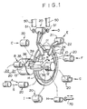
- Figure 1 is a schematic perspective view showing a film magazine assembling system in accordance with an embodiment of the present invention,
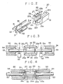
- Figure 2 is an enlarged perspective view showing a part of the system,
- Figures 3 and 4 are views for illustrating the operation of the capping system employed in the film magazine assembling system,
- Figure 5 is a fragmentary cross-sectional view showing a part of the capped barrel plate, and
- Figure 6 is a cross-sectional view showing the cap caulking system employed in the film magazine assembling system.
- In Figure 1, a film magazine assembling system in accordance with an embodiment of the present invention includes an indexing
member 10 which is in the form of a rotary plate rotatable about arotational shaft 12. Nine support members 11 are fixed to the indexingmember 10 at equidistance from therotational shaft 12 and at regular angular intervals of 40° about therotational shaft 12. A fixedhalf 21 of a magazine casing assembling chuck 20 (to be described in detail later) is fixed to each support member 11. Therotational shaft 12 is connected to an indexer driving means 13 and the indexingmember 10 is intermittently rotated by 40° in the direction of arrow R in Figure 1 by the indexer driving means 13. - The other or
movable half 22 of the magazinecasing assembling chuck 20 is connected to the outer end of achuck driving lever 23 which is pivoted to the support member 11 by apivot pin 24 which extends in parallel to therotational shaft 12. A cam member having anannular cam groove 14 is mounted on therotational shaft 12 coaxially with the indexingmember 10 so that it is rotatable relative to the indexingmember 10 and thecam groove 14 surrounds therotational shaft 12. Acam follower 25 in engagement with thecam groove 14 is mounted on the inner end of thechuck driving lever 23. When the indexingmember 10 is rotated about therotational shaft 12, thechuck driving lever 23 is swung under the guidance of thecam groove 14, whereby themovable half 22 of the magazinecasing assembling chuck 20 is moved away from or toward thefixed half 21 in predetermined positions. The same behavior of themovable half 22 can be caused when the cam member is rotated with the indexingmember 10 kept stationary. - The magazine
casing assembling chuck 20 will be described in detail with reference to Figure 2, hereinbelow. Thefixed half 21 and themovable half 22 are respectively provided withinner surfaces 21a and 22a which form a part of a cylindrical surface. When thechuck driving lever 23 is swung to a predetermined closing position, themovable half 22 is opposed close to the fixedhalf 21. This state of the magazinecasing assembling chuck 20 will be referred to as "closed state", hereinbelow. In the closed state of the magazinecasing assembling chuck 20, first andsecond side edges fixed half 21 are respectively opposed to first andsecond side edges movable half 22 with thefirst side edges fixed half 21 and theinner surfaces 22a of themovable half 22 form a substantially cylindrical cavity. On the other hand, when thechuck driving lever 23 is swung to a predetermined opening position, themovable half 22 is moved away from thefixed half 21. This state of the magazinecasing assembling chuck 20 will be referred to as "open state", hereinbelow. Thefirst side edge 21b of thefixed half 21 is sharp. A barrelplate pushing bar 27 is provided on theinner surface 22a of themovable half 22 and is urged toward the fixedhalf 21 by a pair ofsprings 26. - The indexing
member 10 successively brings each magazinecasing assembling chuck 20 to first to ninth stations A to I (Figure 1). In the first station A, the magazinecasing assembling chuck 20 is stopped in the open state, and abarrel plate 30 is loaded into the magazinecasing assembling chuck 20. The means for feeding thebarrel plate 30, which is omitted in Figure 1, will be described with reference to Figure 2, hereinbelow. Abarrel plate 30 which has been rolled into a predetermined shape is conveyed along abarrel plate guide 31 to the first station A in the longitudinal direction of the magazinecasing assembling chuck 20 as stopped at the first station A (the direction of arrow S). At this time, thebarrel plate 30 is conveyed with the opening between its opposed side edges (which forms the magazine slit) directed upward. A pair of feedingclaws 32 pushes thebarrel plate 30 away from thebarrel plate guide 31 into the magazinecasing assembling chuck 20 which is in the open state. At this time, the opposed side edges of thebarrel plate 30 is positioned between the first side edges 21b and 22b of the fixed andmovable halves casing assemling chuck 20. The end portion of the barrelplate pushing bar 27 facing thebarrel plate guide 31 is tapered so that it gradually displaces thebarrel plate 30 toward the fixedhalf 21 as thebarrel plate 30 is inserted into the magazinecasing assembling chuck 20, thereby bringing thebarrel plate 30 into close contact with the inner surface 21a of the fixedhalf 21. This arrangement is advantageous in that thebarrel plate 30 can be certainly brought into close contact with the inner surface 21a of the fixedhalf 21 even if the fixed andmovable halves halves barrel plate 30 is prevented from impacting against the magazinecasing assembling chuck 20 and being damaged. - After the
barrel plate 30 is loaded into the magazinecasing assembling chuck 20, the indexingmember 10 indexes. During the indexing, that is, on the way to the second station B, the magazinecasing assembling chuck 20 is partly closed by thechuck driving lever 23. When the magazinecasing assembling chuck 20 is partly closed, thebarrel plate 30 is pushed toward the fixedhalf 21 by the pushingbar 27 and the turnededge portion 30a of thebarrel plate 30 is brought into engagement with thefirst side edge 21b of the fixedhalf 21. When the magazinecasing assembling chuck 20 is subsequently opened before it reaches the second station B, thebarrel plate 30 is held in close contact with the substantially entire inner surface 21a of the fixedhalf 21. Thebarrel plate 30 is thus accurately positioned with respect to the magazinecasing assembling chuck 20. The fixedhalf 21 covers an angle slightly larger than 180°, which contributes toward confining thebarrel plate 30 in the fixedhalf 21. - When the magazine
casing assembling chuck 20 carrying thereon thebarrel plate 30 reaches the second station B and is stopped there, a film assembly which comprises aspool 35 and aroll film 38 wound around the spool 35 (Figure 1) is loaded into thebarrel plate 30. Thespool 35 is held by apallet 37 in parallel to aguide rail 35 along which thepallet 37 moves. Further, thepallet 37 has a pair of pinch arms 39 (only one of which is seen in Figure 1) which pinches the leader portion of theroll film 38. When thepallet 37 is moved leftward (as seen in Figure 1) by a predetermined distance, the film assembly is inserted into thebarrel plate 30 while the leader portion of theroll film 38 moves through the opening between the spaced side edges of thebarrel plate 30. Then, after thepallet 37 releases thespool 35 and thepinch arms 39 releases thefilm 38, thepallet 37 is returned rightward leaving the film assembly in thebarrel plate 30. - Thereafter, the magazine
casing assembling chuck 20 is closed and thebarrel plate 30 is thereby closed, and then the magazinecasing assembling chuck 20 is sent to the fourth station D through the third station C which is an idle station. At the fourth station D, thebarrel plate 30 is capped. The capping operation will be described with reference to Figures 3 and 4. A pair ofcap chutes 50 are disposed on opposite sides of the magazinecasing assembling chuck 20 stopped at the fourthstation D. Caps 51 are correctly oriented in thecap chutes 51 and are fed tolocator arms 52 on opposite sides of the magazinecasing assembling chuck 20 so as to stand erect on therespective locator arms 52 as shown in Figure 3. Thearms 52 are actuated when thecaps 51 are fed thereto and bring thecaps 51 into alignment with the magazinecasing assembling chuck 20. At the fourth station D, a pair ofguide shafts 53 which are circular in cross-section are disposed coaxially with each other and spaced from each other by a predetermined distance. A cylindricalcap pushing member 54 is fitted on eachguide shaft 53 and a cylindricalcap confining member 55 is fitted on thecap pushing member 54. When the magazinecasing assembling chuck 20 is stopped at the fourth station D, thechuck 20 is positioned betweenguide shafts 53 in alignment with theshafts 53. Theshaft 53, the pushingmember 54 and the confiningmember 55 are moved in the longitudinal direction of theguide shaft 53 by driving means which are not shown, and are moveable relative to each other. When thecaps 51 are positioned in alignment with the magazinecasing assembling chuck 20, theguide shafts 53 are moved toward each other and toward the magazinecasing assembling chuck 20 so that the leftside guide shaft 53 passes through the boss hole 51a of theleft side cap 51 and the tip of the leftside guide shaft 53 is fitted into thelonger boss portion 35c of thespool 35 and so that the right side guide shaft 63 passed through the boss hole 51a of theright side cap 51 and the tip of the rightside guide shaft 53 is fitted into the shorter boss portion 53d of thespool 35. (The tip of theguide shaft 53 is slightly smaller than the other portion in diameter.) Thus thecaps 51 are located with respect to thespool 35 and accordingly to thebarrel plate 30 which is substantially cylindrical. The state at this time is shown in Figure 3. Thereafter thelocator arms 52 are moved away from thecaps 51, and thecap pushing member 54 and the confiningmember 55 on each side are moved toward the magazinecasing assembling chuck 20, whereby thecaps 51 are pushed toward the magazinecasing assembling chuck 20 along theguide shaft 53. Thus the innerperipheral surface 55a of the leading end portion of each confiningmember 55 is fitted on the outerperipheral surface 20e of the corresponding end portion of the magazinecasing assembling chuck 20 as shown in Figure 4. Thecap pushing members 54 are further moved toward the magazinecasing assembling chuck 20 after the confiningmembers 55 are stopped and the left andright caps 51 are fitted on the end portions of thebarrel plate 30. When eachcap 51 is fitted on thebarrel plate 30, the outer peripheral portion of thecap 51 is drawn under the guidance of the innerperipheral surface 20f of the end portion of the magazinecasing assembing chuck 20 and is temporarily caulked as shown in Figure 5. Though a force which urges outward the magazinecasing assembling chuck 20 when thecaps 51 are fitted on thebarrel plate 30, thechuck 20 is prevented from opening since the confiningmembers 55 have been fitted on thechuck 20. Further, since thecaps 51 are slid on theguide shafts 53 when they are fitted on thebarrel plate 30, they cannot fall or incline during the capping operation. Further, since thecaps 51 have been correctly located with respect to thebarrel plate 30 by theguide shaft 53, the capping operation can be performed with a high accuracy. Thereafter, theguide shafts 53, thecap pushing members 54 and the confiningmembers 55 are returned to the original position. - The magazine
casing assembling chuck 20 carrying thereon the cappedbarrel plate 30 is subsequently sent to the fifth station E where thecaps 51 are caulked. Since thecaps 51 have been temporarily caulked, thecaps 51 cannot be removed from thebarrel plate 30 during transfer to the fifth station E. The caulking of thecaps 51 will be described with reference to Figure 6, hereinbelow. Figure 6 shows caulking means which are omitted in Figure 1. When the magazinecasing assembling chuck 20 is stopped at the fifth station E, thechuck 20 is positioned between a pair of caulking units. Each caulking units comprises a cylindricalchuck confining member 60 which is similar to the confiningmember 55 and is moved toward and away from the magazinecasing assembling chuck 20, aclaw pushing shaft 61 which is moved back and forth in the longitudinal direction thereof relative to thechuck confining member 60, and a plurality (e.g., eight) ofcaulking claws 62 disposed about theshaft 61 at regular intervals. The tip portion of eachcaulking claw 62 is directed radially outwardly of theshaft 61 and is supported to be movable in the radial direction of theshaft 61. The inner surface of thecaulking claw 62 is inclined inwardly toward thebarrel plate 30 and the tip portion of theshaft 61 is tapered so as to conform to the inclination of the inner surface of thecaulking claws 62. When caulking thecaps 51, the caulking units are moved toward the magazinecasing assembling chuck 20 so that the innerperipheral surface 60a of the tip portion of each confiningmember 60 is fitted on the outerperipheral surface 20e of the magazinecasing assembling chuck 20 as shown in Figure 6. At this time, the tip portions of thecaulking claws 62 are positioned inside the peripheral wall portion of thecap 51. When theclaw pushing shafts 61 are subsequently moved toward the magazinecasing assembling chuck 20, theclaws 62 are pushed radially outwardly by way of engagement of the tapered tip portion of theshaft 61 and the inclined inner surfaces of theclaws 62, and the peripheral wall portion of thecaps 51 are bent outwardly, whereby the twocaps 51 are simultaneously caulked to thebarrel plate 30. Also in this case, thechuck 20 is prevented from opening since the confiningmembers 60 have been fitted on thechuck 20. When the caulking operation is completed, the caulking units are moved away from the magazinecasing assembling chuck 20. - Thereafter, the indexing
member 10 is operated and the magazinecasing assembling chuck 20 carrying thereon the completed film magazine is sent to the sixth station F. At the station F, it is checked whether thebarrel plate 30 is provided with caps on the respective ends. Thereafter, the indexingmember 10 brings the magazinecasing assembling chuck 20 to the seventh station G, where the chuck center is checked. Thereafter, the magazinecasing assembling chuck 20 is brought to the eighth station H by the indexingmember 10 and is opened at the station H. Amagazine discharging means 70 is ten operated and discharges the completed film magazine in the magazinecasing assembling chuck 20 onto a belt conveyor, for instance. The magazine discharging means 70 may comprise rod-like member which is pushed into the magazinecasing assembling chuck 20 in the longitudinal direction of thechuck 20. - Thereafter, the magazine
casing assembling chuck 20 is brought to the ninth station I, where residue in thechuck 20 is removed. Then the magazinecasing assembling chuck 20 is returned to the first station A, and the operations described above are repeated while the magazinecasing assembling chuck 20 is transferred from station to station.
Claims (4)
a plurality of two-part magazine casing assembling chucks, each comprising a pair of chuck members the inner surfaces of which are a part of a cylindrical surface in shape and which can be selectively brought into a closed state where the chuck members are mated with each other so that the inner surfaces thereof substantially form a cylindrical surface and into an open state where one of the side edges of one of the chuck members parallel to the longitudinal axis of the cylindrical surface is spaced from the mating edge of the other chuck member,
an indexing means which is rotatable about a substantially horizontal rotational axis and supports the magazine casing assembling chucks at regular angular intervals about the rotational axis so that the longitudinal axis of said cylindrical surface is held horizontal,
an indexing means driving means which intermittently rotates the indexing means by an angle equal to the angular interval, thereby successively stopping each magazine casing assembling chuck at a plurality of stations,
a barrel plate feeding means which loads a barrel plate into each magazine casing assembling chuck at a first station, opposed side edges of the barrel plate which form the magazine slit being spaced from each other at the first station, the magazine casing assembling chuck being in the open state and the barrel plate being loaded into the magazine casing assembling chuck so that the side edges are positioned in the space between the spaced side edges of the chuck members,
a film assembly feeding means which moves a film assembly comprising a spool and a roll film wound around the spool in the longitudinal direction of the spool and loads the film assembly into the barrel plate carried by the magazine casing assembly chuck when the magazine casing assembling chuck which has been fed with the barrel plate is stopped at a second station,
a chuck driving means which brings the magazine casing assembling chuck which has been fed with the barrel plate and the film assembly into the closed state, thereby closing the barrel plate,
a capping system which mounts caps on respective ends of the closed barrel plate when the magazine casing assembling chuck carrying thereon the closed barrel plate is stopped at a third station, and
a film magazine discharging means which discharges the capped barrel plate with the film assembly accommodated therein from the magazine casing assembling chuck which has been in an open state.
a cap feeding means which positions a pair of caps to be opposed to the respective ends of the barrel plate, each cap having a boss hole to be engaged with an end of the spool,
a pair of guide shafts which are opposed to the respective ends of the barrel plate and is adapted to be moved toward the barrel plate through the boss holes of the caps so that the tip portions of the respective guide shafts are fitted in the respective ends of the spool,
a pair of cap pushing means which respectively pushes the caps along the guide shafts toward the ends of the barrel plate so as to be engaged with the respective ends of the barrel plate, and
a pair of cap caulking means each of which comprises a plurality of caulking claws which are disposed about an axis and supported so that their tip portions are movable away from and toward the axis, and a claw driving member which moves the caulking claws toward and away from the axis, is moved after said guide shafts are moved away from the barrel plate so that the tip portions of the caulking claws are positioned inside the peripheral wall portion of the cap, and causes the claw driving member to force the claws into the peripheral wall portion of the cap.
a pair of chuck members the inner surfaces of which are a part of a cylindrical surface in shape and which can be selectively brought into a closed state where the chuck members are mated with each other so that the inner surfaces thereof substantially form a cylindrical surface and into an open state where one of the side edges of one of the chuck members parallel to the longitudinal axis of the cylindrical surface is spaced from the mating edge of the other chuck member,
an edge portion with which a turned edge portion of a barrel plate for forming the magazine slit is to be engaged being provided on said one side edges of said one chuck member,
a barrel plate pushing member which resiliently pushes the barrel plate positioned between the chuck members toward said one chuck member being provided on the other chuck member.
Applications Claiming Priority (2)
| Application Number | Priority Date | Filing Date | Title |
|---|---|---|---|
| JP63118499A JPH0833625B2 (en) | 1988-05-16 | 1988-05-16 | Patrone assembly device |
| JP118499/88 | 1988-05-16 |
Publications (3)
| Publication Number | Publication Date |
|---|---|
| EP0342605A2 true EP0342605A2 (en) | 1989-11-23 |
| EP0342605A3 EP0342605A3 (en) | 1991-07-10 |
| EP0342605B1 EP0342605B1 (en) | 1995-03-29 |
Family
ID=14738184
Family Applications (1)
| Application Number | Title | Priority Date | Filing Date |
|---|---|---|---|
| EP89108776A Expired - Lifetime EP0342605B1 (en) | 1988-05-16 | 1989-05-16 | Film magazine assembling system |
Country Status (6)
| Country | Link |
|---|---|
| US (2) | US5038464A (en) |
| EP (1) | EP0342605B1 (en) |
| JP (1) | JPH0833625B2 (en) |
| CN (1) | CN1021991C (en) |
| AU (1) | AU606521B2 (en) |
| DE (1) | DE68921921T2 (en) |
Cited By (2)
| Publication number | Priority date | Publication date | Assignee | Title |
|---|---|---|---|---|
| WO1992010783A1 (en) * | 1990-12-06 | 1992-06-25 | Eastman Kodak Company | Apparatus and method for forming and loading magazines for prewound spools of web material |
| EP1067428B1 (en) * | 1999-07-07 | 2006-09-13 | Fuji Photo Film Co., Ltd. | Method of and apparatus for manufacturing film cartridge |
Families Citing this family (23)
| Publication number | Priority date | Publication date | Assignee | Title |
|---|---|---|---|---|
| JP2785152B2 (en) * | 1990-04-26 | 1998-08-13 | コニカ株式会社 | Patrone body forming equipment |
| US5074034A (en) * | 1990-12-06 | 1991-12-24 | Eastman Kodak Company | Apparatus for staking end caps onto a cylindrical shell |
| US5105535A (en) * | 1990-12-06 | 1992-04-21 | Eastman Kodak Company | Apparatus for positioning a spool or similar object |
| US5044144A (en) * | 1990-12-06 | 1991-09-03 | Eastman Kodak Company | Apparatus and method for forming and loading a magazine for prewound spools of web material |
| US5119549A (en) * | 1990-12-06 | 1992-06-09 | Eastman Kodak Company | Apparatus and method for applying end caps to cylindrical shells |
| US5125254A (en) * | 1990-12-06 | 1992-06-30 | Eastman Kodak Company | Apparatus for forming a very open shell for lateral loading of product |
| US5088784A (en) * | 1990-12-06 | 1992-02-18 | Eastman Kodak Company | Apparatus and method for transferring a spool of web material |
| US5117688A (en) * | 1990-12-06 | 1992-06-02 | Eastman Kodak Company | Apparatus and method for removing a very open shell from a forming mandrel |
| US5210920A (en) * | 1991-08-29 | 1993-05-18 | Xerox Corporation | Apparatus and method for precision assembly of photoreceptor drums |
| DE69321428T2 (en) | 1992-08-03 | 1999-03-04 | Fuji Photo Film Co., Ltd., Minami-Ashigara, Kanagawa | Process for producing a photographic film and a photographic film cassette |
| JPH07311443A (en) * | 1994-05-17 | 1995-11-28 | Fuji Photo Film Co Ltd | Method and device for assembling photographic film cartridge |
| SE508127C2 (en) * | 1994-07-12 | 1998-08-31 | Valeo Engine Cooling Ab | Device and method for providing an end closure |
| US5511300A (en) * | 1994-08-03 | 1996-04-30 | Eastman Kodak Company | Apparatus and method for assembling disks to an arbor |
| US6357102B1 (en) * | 1995-09-13 | 2002-03-19 | Johnson & Johnson Consumer Comapnies, Inc. | System for assembling dental floss dispenser components |
| US6018929A (en) * | 1996-12-27 | 2000-02-01 | Fuji Photo Film Co., Ltd. | Apparatus for processing and packaging photographic film, mechanism for and method of feeding resin components |
| US6009613A (en) * | 1997-03-07 | 2000-01-04 | Eastman Kodak Company | Method for closing a preform shell about a film spool or similar object |
| US6600240B2 (en) | 1997-08-08 | 2003-07-29 | General Electric Company | Variable speed wind turbine generator |
| US6171000B1 (en) * | 1998-12-16 | 2001-01-09 | Eastman Kodak Company | Gimbaled roller assembly process and device |
| JP2003322930A (en) * | 2002-05-07 | 2003-11-14 | Fuji Photo Film Co Ltd | Cartridge forming device |
| US6948237B2 (en) | 2002-03-15 | 2005-09-27 | Fuji Photo Film Co., Ltd. | Methods for manufacturing film cartridge and for feeding plate material |
| US10264876B2 (en) * | 2015-02-27 | 2019-04-23 | Daisaku Shoji Ltd. | Oral cleaning device |
| CN111644833A (en) * | 2020-03-20 | 2020-09-11 | 苏州倍苏自动化科技有限公司 | Automatic laminating lamination equipment of full-automatic table lid |
| CN113909834B (en) * | 2021-09-27 | 2024-04-16 | 东创智造(浙江)有限公司 | Kit end cover equipment |
Citations (5)
| Publication number | Priority date | Publication date | Assignee | Title |
|---|---|---|---|---|
| US2940232A (en) * | 1956-04-11 | 1960-06-14 | Eastman Kodak Co | 135 automatic spooling machine |
| US3364552A (en) * | 1965-11-18 | 1968-01-23 | Kahle Engineering Company | Method and means for assembling and loading film cartridges |
| DE2720780A1 (en) * | 1976-05-10 | 1977-11-24 | Fuji Photo Film Co Ltd | METHOD AND DEVICE FOR FITTING A MAGAZINE WITH A PHOTO FILM STRIP AND AT THE SAME TIME ASSEMBLING THE MAGAZINE |
| DE3402841A1 (en) * | 1983-02-03 | 1984-08-09 | Fuji Photo Film Co., Ltd., Minami Ashigara, Kanagawa | FILM LOADING METHOD AND DEVICE |
| JPS6375735A (en) * | 1986-09-19 | 1988-04-06 | Konica Corp | Method and apparatus for capping photographic cartridge |
Family Cites Families (6)
| Publication number | Priority date | Publication date | Assignee | Title |
|---|---|---|---|---|
| CH486048A (en) * | 1968-04-27 | 1970-02-15 | Agfa Gevaert Ag | Method and apparatus for winding photographic film tape onto a spool disposed within a cassette |
| GB1283214A (en) * | 1969-08-25 | 1972-07-26 | Kahle Engineering Company | Method and means for loading film cartridges |
| JPS6053868B2 (en) * | 1976-03-24 | 1985-11-27 | 富士写真フイルム株式会社 | Film winding device |
| JPS5577949A (en) * | 1978-12-07 | 1980-06-12 | Fuji Kiki Kogyo Kk | Molding device of photographic patrone or the like |
| US4848693A (en) * | 1988-05-12 | 1989-07-18 | Eastman Kodak Company | Film cassette |
| US4924419A (en) * | 1988-05-24 | 1990-05-08 | Eastman Kodak Company | System and a method for detecting a malfunction in the operation of a parts assembly machine |
-
1988
- 1988-05-16 JP JP63118499A patent/JPH0833625B2/en not_active Expired - Fee Related
-
1989
- 1989-05-15 CN CN89103508A patent/CN1021991C/en not_active Expired - Fee Related
- 1989-05-16 DE DE68921921T patent/DE68921921T2/en not_active Expired - Fee Related
- 1989-05-16 US US07/352,310 patent/US5038464A/en not_active Expired - Lifetime
- 1989-05-16 EP EP89108776A patent/EP0342605B1/en not_active Expired - Lifetime
- 1989-05-16 AU AU34835/89A patent/AU606521B2/en not_active Ceased
-
1990
- 1990-01-18 US US07/467,082 patent/US4974316A/en not_active Expired - Lifetime
Patent Citations (5)
| Publication number | Priority date | Publication date | Assignee | Title |
|---|---|---|---|---|
| US2940232A (en) * | 1956-04-11 | 1960-06-14 | Eastman Kodak Co | 135 automatic spooling machine |
| US3364552A (en) * | 1965-11-18 | 1968-01-23 | Kahle Engineering Company | Method and means for assembling and loading film cartridges |
| DE2720780A1 (en) * | 1976-05-10 | 1977-11-24 | Fuji Photo Film Co Ltd | METHOD AND DEVICE FOR FITTING A MAGAZINE WITH A PHOTO FILM STRIP AND AT THE SAME TIME ASSEMBLING THE MAGAZINE |
| DE3402841A1 (en) * | 1983-02-03 | 1984-08-09 | Fuji Photo Film Co., Ltd., Minami Ashigara, Kanagawa | FILM LOADING METHOD AND DEVICE |
| JPS6375735A (en) * | 1986-09-19 | 1988-04-06 | Konica Corp | Method and apparatus for capping photographic cartridge |
Non-Patent Citations (2)
| Title |
|---|
| PATENT ABSTRACTS OF JAPAN, vol. 12, no. 303 (P-746)[3150], 18th August 1988; & JP-A-63 75 735 (KONICA CORP.) 06-04-1988 * |
| PATENT ABSTRACTS OF JAPAN, vol. 13, no. 50 (P-823)[3398], 6th February 1989; & JP-A³63 243 938 (FUJI PHOTO FILM) 11-10-1988 * |
Cited By (2)
| Publication number | Priority date | Publication date | Assignee | Title |
|---|---|---|---|---|
| WO1992010783A1 (en) * | 1990-12-06 | 1992-06-25 | Eastman Kodak Company | Apparatus and method for forming and loading magazines for prewound spools of web material |
| EP1067428B1 (en) * | 1999-07-07 | 2006-09-13 | Fuji Photo Film Co., Ltd. | Method of and apparatus for manufacturing film cartridge |
Also Published As
| Publication number | Publication date |
|---|---|
| DE68921921D1 (en) | 1995-05-04 |
| AU606521B2 (en) | 1991-02-07 |
| CN1021991C (en) | 1993-09-01 |
| JPH01287670A (en) | 1989-11-20 |
| JPH0833625B2 (en) | 1996-03-29 |
| EP0342605A3 (en) | 1991-07-10 |
| AU3483589A (en) | 1989-11-16 |
| EP0342605B1 (en) | 1995-03-29 |
| CN1038625A (en) | 1990-01-10 |
| US5038464A (en) | 1991-08-13 |
| DE68921921T2 (en) | 1995-08-03 |
| US4974316A (en) | 1990-12-04 |
Similar Documents
| Publication | Publication Date | Title |
|---|---|---|
| EP0342605B1 (en) | Film magazine assembling system | |
| US4115913A (en) | Method and apparatus for wind loading film magazines | |
| US5044144A (en) | Apparatus and method for forming and loading a magazine for prewound spools of web material | |
| US4656737A (en) | Film loading apparatus | |
| US5119549A (en) | Apparatus and method for applying end caps to cylindrical shells | |
| US20020028078A1 (en) | Method and apparatus for manufacturing photographic film and photographic film cassette | |
| US6393695B2 (en) | Automatic assembling method and apparatus for assembling photographic film cassettes | |
| US3921278A (en) | Method and apparatus for removing roll film from cassettes | |
| US6519839B1 (en) | Method of and apparatus for manufacturing film cartridge | |
| EP0677769B1 (en) | Method and apparatus for assembling photographic film cassette | |
| US4006862A (en) | Armature winding apparatus with improved armature loading and unloading mechanism | |
| US5088784A (en) | Apparatus and method for transferring a spool of web material | |
| US5645240A (en) | Apparatus for inserting film into a spool | |
| US5125254A (en) | Apparatus for forming a very open shell for lateral loading of product | |
| JPH1020454A (en) | Method and device for packaging photographic sensitive film | |
| EP0867755B1 (en) | Spooling equipment | |
| EP0514533B1 (en) | Apparatus and method for forming and loading magazines for prewound spools of web material | |
| EP0867756B1 (en) | Apparatus for closing a preform shell about a film spool or similar object | |
| US6009613A (en) | Method for closing a preform shell about a film spool or similar object | |
| US5875667A (en) | Apparatus for forming a slightly open shell for loading of product | |
| JPH0428492B2 (en) | ||
| JP2001290245A (en) | Method for manufacturing photographic apparatus | |
| JPH08339811A (en) | Assembling device for battery cell |
Legal Events
| Date | Code | Title | Description |
|---|---|---|---|
| PUAI | Public reference made under article 153(3) epc to a published international application that has entered the european phase |
Free format text: ORIGINAL CODE: 0009012 |
|
| AK | Designated contracting states |
Kind code of ref document: A2 Designated state(s): DE GB NL |
|
| PUAL | Search report despatched |
Free format text: ORIGINAL CODE: 0009013 |
|
| AK | Designated contracting states |
Kind code of ref document: A3 Designated state(s): DE GB NL |
|
| RHK1 | Main classification (correction) |
Ipc: G03B 17/26 |
|
| 17P | Request for examination filed |
Effective date: 19910911 |
|
| 17Q | First examination report despatched |
Effective date: 19931011 |
|
| GRAA | (expected) grant |
Free format text: ORIGINAL CODE: 0009210 |
|
| AK | Designated contracting states |
Kind code of ref document: B1 Designated state(s): DE GB NL |
|
| REF | Corresponds to: |
Ref document number: 68921921 Country of ref document: DE Date of ref document: 19950504 |
|
| PLBE | No opposition filed within time limit |
Free format text: ORIGINAL CODE: 0009261 |
|
| STAA | Information on the status of an ep patent application or granted ep patent |
Free format text: STATUS: NO OPPOSITION FILED WITHIN TIME LIMIT |
|
| 26N | No opposition filed | ||
| REG | Reference to a national code |
Ref country code: GB Ref legal event code: IF02 |
|
| PGFP | Annual fee paid to national office [announced via postgrant information from national office to epo] |
Ref country code: GB Payment date: 20040513 Year of fee payment: 16 |
|
| PGFP | Annual fee paid to national office [announced via postgrant information from national office to epo] |
Ref country code: NL Payment date: 20040517 Year of fee payment: 16 |
|
| PGFP | Annual fee paid to national office [announced via postgrant information from national office to epo] |
Ref country code: DE Payment date: 20040629 Year of fee payment: 16 |
|
| PG25 | Lapsed in a contracting state [announced via postgrant information from national office to epo] |
Ref country code: GB Free format text: LAPSE BECAUSE OF NON-PAYMENT OF DUE FEES Effective date: 20050516 |
|
| PG25 | Lapsed in a contracting state [announced via postgrant information from national office to epo] |
Ref country code: NL Free format text: LAPSE BECAUSE OF NON-PAYMENT OF DUE FEES Effective date: 20051201 Ref country code: DE Free format text: LAPSE BECAUSE OF NON-PAYMENT OF DUE FEES Effective date: 20051201 |
|
| GBPC | Gb: european patent ceased through non-payment of renewal fee |
Effective date: 20050516 |
|
| NLV4 | Nl: lapsed or anulled due to non-payment of the annual fee |
Effective date: 20051201 |