EP0342383A1 - Ventilantrieb mit Ventilspielausgleich für Brennkraftmaschine mit obenliegenden Ventilen - Google Patents
Ventilantrieb mit Ventilspielausgleich für Brennkraftmaschine mit obenliegenden Ventilen Download PDFInfo
- Publication number
- EP0342383A1 EP0342383A1 EP89107234A EP89107234A EP0342383A1 EP 0342383 A1 EP0342383 A1 EP 0342383A1 EP 89107234 A EP89107234 A EP 89107234A EP 89107234 A EP89107234 A EP 89107234A EP 0342383 A1 EP0342383 A1 EP 0342383A1
- Authority
- EP
- European Patent Office
- Prior art keywords
- rocker arm
- head
- push rod
- stud
- cylinder head
- Prior art date
- Legal status (The legal status is an assumption and is not a legal conclusion. Google has not performed a legal analysis and makes no representation as to the accuracy of the status listed.)
- Granted
Links
Images

Classifications
-
- F—MECHANICAL ENGINEERING; LIGHTING; HEATING; WEAPONS; BLASTING
- F01—MACHINES OR ENGINES IN GENERAL; ENGINE PLANTS IN GENERAL; STEAM ENGINES
- F01L—CYCLICALLY OPERATING VALVES FOR MACHINES OR ENGINES
- F01L1/00—Valve-gear or valve arrangements, e.g. lift-valve gear
- F01L1/12—Transmitting gear between valve drive and valve
- F01L1/14—Tappets; Push rods
-
- F—MECHANICAL ENGINEERING; LIGHTING; HEATING; WEAPONS; BLASTING
- F01—MACHINES OR ENGINES IN GENERAL; ENGINE PLANTS IN GENERAL; STEAM ENGINES
- F01L—CYCLICALLY OPERATING VALVES FOR MACHINES OR ENGINES
- F01L1/00—Valve-gear or valve arrangements, e.g. lift-valve gear
- F01L1/12—Transmitting gear between valve drive and valve
- F01L1/18—Rocking arms or levers
- F01L1/181—Centre pivot rocking arms
- F01L1/182—Centre pivot rocking arms the rocking arm being pivoted about an individual fulcrum, i.e. not about a common shaft
- F01L1/183—Centre pivot rocking arms the rocking arm being pivoted about an individual fulcrum, i.e. not about a common shaft of the boat type
-
- F—MECHANICAL ENGINEERING; LIGHTING; HEATING; WEAPONS; BLASTING
- F01—MACHINES OR ENGINES IN GENERAL; ENGINE PLANTS IN GENERAL; STEAM ENGINES
- F01L—CYCLICALLY OPERATING VALVES FOR MACHINES OR ENGINES
- F01L1/00—Valve-gear or valve arrangements, e.g. lift-valve gear
- F01L1/20—Adjusting or compensating clearance
-
- F—MECHANICAL ENGINEERING; LIGHTING; HEATING; WEAPONS; BLASTING
- F01—MACHINES OR ENGINES IN GENERAL; ENGINE PLANTS IN GENERAL; STEAM ENGINES
- F01L—CYCLICALLY OPERATING VALVES FOR MACHINES OR ENGINES
- F01L1/00—Valve-gear or valve arrangements, e.g. lift-valve gear
- F01L1/46—Component parts, details, or accessories, not provided for in preceding subgroups
-
- F—MECHANICAL ENGINEERING; LIGHTING; HEATING; WEAPONS; BLASTING
- F02—COMBUSTION ENGINES; HOT-GAS OR COMBUSTION-PRODUCT ENGINE PLANTS
- F02B—INTERNAL-COMBUSTION PISTON ENGINES; COMBUSTION ENGINES IN GENERAL
- F02B2275/00—Other engines, components or details, not provided for in other groups of this subclass
- F02B2275/34—Lateral camshaft position
Definitions
- the present invention relates generally to overhead valve internal combustion engines, and more particularly to the valve train of such an engine.
- Air cooled overhead valve internal combustion engines have a cylinder head in which the intake and exhaust valves are slidingly mounted and oriented such that the valve stems extend from the valve head in a direction generally away from the top of the cylinder bore.
- Push rods engaging valve lifters actuated by a cam shaft in the cylinder portion of the engine extend into the cylinder head generally alongside the valve stems.
- a rocker arm Disposed between each valve stem and corresponding push rod is a rocker arm pivotally mounted on a rocker arm stud connected to the cylinder head. The rocker arm engages the push rod at one end and the top of the valve stem at the other end and serves to translate upper movement of the push rod to a corresponding downward movement of the valve stem.
- Prior rocker arm studs are usually fastened at their lower end to the cylinder head either by a tight press-fit into a corresponding bore or by a threading received in a correspondingly threaded bore.
- the upper end of the rocker arm stud is usually threaded and received loosely through an elongate hole in the bottom of the rocker arm.
- a separate spherical-surfaced pivot washer is often disposed about the upper threaded end of the rocker stud in engagement with a corresponding spherical bearing surface inside the rocker arm.
- a locking type of nut is threaded onto the upper end of the rocker arm stud above the spherical pivot washer and is used to adjust the valve lash by moving the rocker arm pivot point upwardly or downwardly by turning the locking nut with respect to the fixed rocker arm stud to a selected position.
- a push rod guide plate is sandwiched between the cylinder head and an integral enlargement of the rocker arm stud.
- the push rod guide plate includes guide tabs disposed on either side of the push rod to control lateral displacement of the push rod in a direction perpendicular to the rocking plane of the rocker arm.
- rocker arm and rocker arm stud One disadvantage of the prior art construction of the rocker arm and rocker arm stud is that a significant amount of space is taken up by the locking nut at the top end of the rocker arm stud. Where the locking nut is recessed between the sidewalls of an open-topped stamped rocker arm, sufficient clearance must be provided between the locking nut and the sidewall for an adjustment wrench. In addition, the height of the rocker arm stud must extend above the spherical pivot washer so that the upper threads of the rocker arm stud can be engaged by the locking nut. These two factors increase the width of the rocker arms and the overall height of the valve mechanism with respect to the head gasket surface.
- the present invention involves an improved rocker arm stud cooperating with a rocker arm which permits a compact rocker arm and valve train construction and provides for ease of valve lash adjustment without disturbing the push rod guide plate.
- the rocker arm stud is an integral piece having a threaded shank threadedly received in the cylinder head and a head portion having an integral bearing surface in engagement with a bearing surface on the rocker arm.
- the head of the rocker arm stud includes tool engaging means recessed in the top surface thereof for engaging a tool to rotate the rocker arm stud for valve lash adjustment.
- the present invention provides an improvement over the prior art in that the bearing surface associated with the rocker arm stud is formed integrally with the rocker arm stud which eliminates separate bearing washer.
- the valve lash is adjusted by rotating the rocker arm stud such that the threaded shank thereof moves into or out of the cylinder head at the lower end of the rocker arm stud.
- the overall height of the valve train is reduced by eliminating the adjustable lock nut at the top of the rocker arm stud as used in the prior art for valve lash adjustment.
- locking means are provided at the lower end of the rocker arm stud for both holding the push rod guide plate in place and for restraining the rocker arm stud against rotation once the valve lash has been adjusted.
- Provision of tool engaging means recessed in the top surface of the head of the rocker arm stud permits valve lash adjustment with a tool (such as an Allen wrench) having a width less than the head of the rocker arm stud. Consequently, there is no need to provide clearance between the sides of the rocker arm and the rocker arm stud head to accommodate a bulky wrench.
- a tool such as an Allen wrench
- the invention in one form thereof, provides an adjustable lash valve train in combination with an overhead valve internal combustion engine having a cylinder head, a valve reciprocally mounted in the cylinder head, and a push rod.
- a rocker arm is disposed for transmitting motion of the push rod to the valve, with the rocker arm including a bearing surface.
- the rocker arm stud includes a threaded shank and an integral head, with the head having tool engaging means recessed in the top surface thereof and also having an integral bearing surface in engagement with the bearing surface of the rocker arm.
- Threaded means are provided in the cylinder head for threadedly receiving the shank of the rocker arm stud and locking means are provided for selectively locking the threaded shank against rotation with respect to the cylinder head.
- a feature of the present invention is the provision of an adjustable lash valve train which results in a compact arrangement while still permitting the use of a push rod guide plate held to the cylinder head by the rocker arm stud.
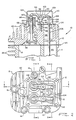
- cylinder head area of an air cooled overhead valve internal combustion engine 10 including cylinder head 12 which is attached to cylinder portion 14 by five cylinder head bolts 16.
- Cylinder portion 14 includes cylinder bore 18, push rod cavity 20 and integral cooling fins 22.
- a metal cylinder head gasket 24 made of a soft aluminum alloy is disposed between cylinder head 12 and cylinder portion 14 to provide a high pressure seal at their interface.
- Head bolts 16 are received through appropriately sized bores 26 in cylinder head 12 and are threadedly received in a corresponding threaded bore in cylinder portion 14.
- a flat metal thrust washer 28 is disposed about the shank 30 of head bolt 16 atop cylinder head 12.
- a dish shaped spring washer 32 is disposed about shank 30 between thrust washer 28 and the underside of head portion 34 of head bolt 16.
- Head bolt 16 is tightened into cylinder portion 14 sufficiently to partially compress spring washer 32, thereby causing spring washer 32 to maintain substantially constant compressive force on metal head gasket 24 through cylinder head 12 despite temperature induced expansion and contraction of the metal parts adjacent head gasket 24 throughout thermal cycling of the engine. This measure allows metal head gasket 24 to maintain its initial sealing effectiveness over time.
- Cylinder head 12 includes a combustion chamber 36 aligned with and in communication with cylinder bore 18, a push rod cavity 38 and integral cooling fins 40.
- Intake valve 42 and exhaust valve 44 seated on valve seats 46 and 48, respectively, provide for selective communication between combustion chamber 36 and intake port 50 and exhaust port 52, respectively.
- Intake valve 42 includes valve stem 54 slidingly received in bearing bushing 56 fitted within boss 58 of cylinder head 12.
- Valve stem 54 includes a reduced neck portion 60 and an end portion 62.
- Intake valve spring 64 engages boss 58 at one end thereof and valve spring keeper 66 at the other end thereof.
- Valve spring keeper 66 engages the underside of end portion 62 adjacent neck portion 60 with intake valve spring 64 disposed in compression between boss 58 and valve end portion 62, whereby intake valve 42 is urged against valve seat 46.
- exhaust valve 44 includes valve stem 68 slidingly received within bearing bushing 70 fitted in boss 72 of cylinder head 12.
- Valve stem 68 includes a reduced neck portion 74 and an end portion 76.
- Exhaust valve spring 78 engages boss 72 at one end thereof and valve spring keeper 80 at the other end thereof.
- Valve spring keeper 80 engages the underside of end portion 76 adjacent neck portion 74 with exhaust valve spring 78 disposed in compression between boss 72 and end portion 76, whereby exhaust valve 44 is urged against valve seat 48.
- Intake valve rocker arm 82 is pivotally mounted to rocker arm stud 84 which has a threaded shank 86 threadedly received in rocker arm support boss 88 of cylinder head 12.
- a hex-faced jam nut 90 is threadedly received about shank 86 of rocker arm stud 84 above support boss 88 and can be tightened with respect to support boss 88 to secure rocker arm stud 84 thereto.
- Rocker arm stud 84 includes an enlarged head portion 94 forged integrally with shank 86.
- Head portion 94 includes a spherically shaped undersurface 96 and a hexagonally shaped recess 98 extending downwardly into head portion 94 coaxially with the axis of shank 86.
- Recess 98 is open at the top surface 100 of head portion 94.
- Rocker arm 82 includes an end 102 in engagement with the top of end portion 62 of valve stem 54. Opposite end 104 of rocker arm 82 engages ball shaped end 106 of push rod 108.
- Push rod 108 extends through push rod guide plate 92 within push rod cavity 38 of cylinder head 12 and into push rod cavity 20 of cylinder portion 14. The end of push rod 108 opposite end 106 engages a valve lifter actuated by a cam on a cam shaft (not shown).
- a rocker arm cover 110 is secured to cylinder head 12 by threaded bolts received in holes 112 and sealed thereto by rocker arm cover gasket 114.
- Push rod guide plate 92 includes rocker arm stud holes 116 and 118 through which the shank of the intake valve rocker arm stud 84 and the exhaust valve rocker arm stud, respectively, are received.
- Guide plate 92 further includes a round aperture 120 of sufficient size to avoid interference with head bolt 16 disposed therein.
- a pair of push rod apertures 122 and 124 are provided in guide plate 92 and positioned for receiving push rod 108 corresponding to intake valve 42 and the push rod corresponding to exhaust valve 44, respectively. Extending inwardly into aperture 122 in the plane of guide plate 92 and extending upwardly from the plan of guide plate 92 are push rod guide tabs 126 and 128. Likewise, similarly shaped push rod guide tabs 130 and 132 are associated with aperture 124.
- Each pair of guide tabs 126 and 128, and 130 and 132 are disposed on either side of a respective push rod. In this orientation, lateral movement of the push rods perpendicular to the rocking plane of the rocker arms is restricted while lateral movement of the push rods in the rocking plane of the rocker arms incidental to the rocking motion of the rocker arms is permitted.
- Apertures 122 and 124 are sized large enough to receive therethrough the ball shaped end of the push rods during assembly. However, the space between each respective pair of guide tabs 126 and 128, and 130 and 132 is such that the guide tabs are closely adjacent the push rods after assembly.
- rocker arm 82 which has a spherical bearing surface 129 in engagement with spherically shaped undersurface 96 of rocker arm stud 84, pivots in a rocking plane generally defined by push rod 108 and valve stem 54.
- the reciprocal motion of push rod 108 is thereby transmitted to end portion 62 of valve 42 such that valve spring 64 is cyclically compressed and valve stem 54 reciprocates within bearing bushing 56.
- valve lash can be readily adjusted by first loosening jam nut 90 with an open end wrench, and then turning rocker arm stud 84 into or out of rocker arm support boss 88 as necessary by use of an Allen wrench inserted into hexagonally shaped recess 98 in the enlarged head portion 94. The height of the pivot point of rocker arm 82 is thereby adjusted. Once the appropriate valve lash has been achieved, jam nut 90 is again tightened against guide plate 92 on support boss 88 while rocker arm stud 84 is prevented from turning by means of the Allen wrench held within recess 98.
- Guide plate 92 is maintained in proper alignment with the push rods by jam nut 90 and also by a second similar jam nut on the exhaust valve rocker arm stud. Since the valve lash of the two valves is adjusted one at a time, guide plate 92 remains securely affixed to cylinder head 12 by at least one jam nut at all times during valve lash adjustment. Consequently, the valve lash of the two valves can be successively adjusted without disturbing the alignment of guide plate 92.
- rocker arm stud 84 By utilizing a hex shaped recess in the head portion of rocker arm stud 84, it is not necessary to provide clearance for a wrench between head portion 94 and the sidewalls 134 and 136 of rocker arm 82. Sidewalls 134 and 136 need only be spaced suffi literallyciently to clear the diameter of head portion 94. Consequently, the width of rocker arm 82 is reduced relative to prior art rocker arms, enabling a lighter and more compact valve train arrangement. Furthermore, since the bearing surface of the rocker arm stud 84 is integral with the stud, a separate spherical bearing washer and upper lock nut are eliminated which results in a lower height profile of the rocker arm stud and consequently the overall height of the cylinder head can be reduced.
- an oil groove 136 is shown in the spherically shaped undersurface 96 of head portion 94 to facilitate lubrication between bearing surface 96 and bearing surface 129 of rocker arm 82.
- valve train of engine 10 has been discussed in detail primarily with respect to intake valve 42, it is to be understood that the rocker arm stud, rocker arm, push rod, and valve mechanism associated with the exhaust valve are substantially similar.
Landscapes
- Engineering & Computer Science (AREA)
- Mechanical Engineering (AREA)
- General Engineering & Computer Science (AREA)
- Valve-Gear Or Valve Arrangements (AREA)
Applications Claiming Priority (2)
| Application Number | Priority Date | Filing Date | Title |
|---|---|---|---|
| US196722 | 1988-05-20 | ||
| US07/196,722 US4856467A (en) | 1988-05-20 | 1988-05-20 | Adjustable lash valve train for overhead valve engine |
Publications (2)
| Publication Number | Publication Date |
|---|---|
| EP0342383A1 true EP0342383A1 (de) | 1989-11-23 |
| EP0342383B1 EP0342383B1 (de) | 1992-01-22 |
Family
ID=22726588
Family Applications (1)
| Application Number | Title | Priority Date | Filing Date |
|---|---|---|---|
| EP89107234A Expired EP0342383B1 (de) | 1988-05-20 | 1989-04-21 | Ventilantrieb mit Ventilspielausgleich für Brennkraftmaschine mit obenliegenden Ventilen |
Country Status (4)
| Country | Link |
|---|---|
| US (1) | US4856467A (de) |
| EP (1) | EP0342383B1 (de) |
| CA (1) | CA1322499C (de) |
| DE (1) | DE68900747D1 (de) |
Cited By (1)
| Publication number | Priority date | Publication date | Assignee | Title |
|---|---|---|---|---|
| WO2005052323A3 (en) * | 2003-11-20 | 2005-07-28 | Dresser Inc | Gasket with pushrod retainer |
Families Citing this family (15)
| Publication number | Priority date | Publication date | Assignee | Title |
|---|---|---|---|---|
| US5044329A (en) * | 1990-06-19 | 1991-09-03 | Vince Jamora | Adjustable pushrod guide plate assembly |
| US5035209A (en) * | 1990-09-21 | 1991-07-30 | Caterpillar Inc. | Retention shelf for an engine |
| US5058542A (en) * | 1991-01-28 | 1991-10-22 | Briggs & Stratton Corporation | Rocker box cover assembly for internal combustion engine |
| US5323741A (en) * | 1993-06-28 | 1994-06-28 | Automotive Racing Products, Inc. | Twelve-point rocker-arm adjusting nut |
| US5415138A (en) * | 1994-02-28 | 1995-05-16 | Brunswick Corporation | Pushrod guide for an overhead valve engine and method of installing the same |
| US5724732A (en) * | 1996-11-18 | 1998-03-10 | Caterpillar Inc. | Method and apparatus for supporting push rods |
| US6273043B1 (en) * | 2000-03-16 | 2001-08-14 | Raymond A. Barton | Mounting plate and rocker arm assembly |
| DE10043234A1 (de) * | 2000-09-02 | 2002-03-14 | Stihl Maschf Andreas | Ventiltrieb mit einem Kipphebel |
| US7028653B2 (en) * | 2002-04-01 | 2006-04-18 | Jesel Daniel H | Roller rocker mounting mechanism |
| US7409939B2 (en) * | 2002-09-16 | 2008-08-12 | Perkins Engines Company Limited | Cylinder head having an integrally cast rocker shaft pedestal |
| US7032562B1 (en) | 2005-04-11 | 2006-04-25 | Dart Machinery, Ltd. | Adjustable guide plate assembly |
| US8056518B1 (en) * | 2009-04-08 | 2011-11-15 | Brunswick Corporation | Valve lash adjustment nut |
| US8251030B2 (en) * | 2009-07-23 | 2012-08-28 | Briggs & Stratton Corporation | Rocker cover system |
| CN104929712A (zh) * | 2015-05-18 | 2015-09-23 | 隆鑫通用动力股份有限公司 | 发动机气门摇臂推杆限位板组合装置 |
| WO2017165259A1 (en) * | 2016-03-22 | 2017-09-28 | Eaton Corporation | Lash adjustment on type ii engine |
Citations (3)
| Publication number | Priority date | Publication date | Assignee | Title |
|---|---|---|---|---|
| DE1202563B (de) * | 1961-09-26 | 1965-10-07 | Ford Werke Ag | Stossstangenfuehrung fuer eine mit auf Kugelkoepfen gelagerten Kipphebeln versehene Ventilsteuerung von Brennkraftmaschinen |
| DE1911299B1 (de) * | 1969-03-06 | 1971-01-14 | Rheinstahl Hanomag Ag | Lagerung fuer Kipphebel von Brennkraftmaschinen |
| US4440121A (en) * | 1982-04-30 | 1984-04-03 | General Motors Corporation | Locknut device for engine rocker arm adjustment |
Family Cites Families (12)
| Publication number | Priority date | Publication date | Assignee | Title |
|---|---|---|---|---|
| US24035A (en) * | 1859-05-17 | Vbntilating-hat | ||
| USRE24035E (en) | 1955-07-12 | Valve rocker mounting | ||
| US2669981A (en) * | 1950-09-02 | 1954-02-23 | Gen Motors Corp | Valve rocker mounting |
| US2771866A (en) * | 1954-07-02 | 1956-11-27 | Thompson Prod Inc | Automatic lash adjuster |
| US3054392A (en) * | 1960-03-24 | 1962-09-18 | Earl A Thompson | Metering valve |
| US3064635A (en) * | 1961-02-21 | 1962-11-20 | Gen Motors Corp | Valve rocker mounting |
| US3301238A (en) * | 1962-02-01 | 1967-01-31 | Gen Motors Corp | Stud mounted rocker and spring |
| US3359959A (en) * | 1966-11-29 | 1967-12-26 | Chrysler Corp | Walking beam rocker arm |
| US3401678A (en) * | 1966-11-29 | 1968-09-17 | Chrysler Corp | Rocker arm guide |
| US3589346A (en) * | 1969-05-06 | 1971-06-29 | Robert C Warren | Overhead valve action and air pollutant device |
| US3592174A (en) * | 1970-03-03 | 1971-07-13 | Gen Motors Corp | Valve rocker arm |
| US4601267A (en) * | 1985-07-26 | 1986-07-22 | Tecumseh Products Company | Valve mechanism lubrication system for an overhead valve engine |
-
1988
- 1988-05-20 US US07/196,722 patent/US4856467A/en not_active Expired - Lifetime
- 1988-11-18 CA CA000583585A patent/CA1322499C/en not_active Expired - Fee Related
-
1989
- 1989-04-21 DE DE8989107234T patent/DE68900747D1/de not_active Expired - Fee Related
- 1989-04-21 EP EP89107234A patent/EP0342383B1/de not_active Expired
Patent Citations (3)
| Publication number | Priority date | Publication date | Assignee | Title |
|---|---|---|---|---|
| DE1202563B (de) * | 1961-09-26 | 1965-10-07 | Ford Werke Ag | Stossstangenfuehrung fuer eine mit auf Kugelkoepfen gelagerten Kipphebeln versehene Ventilsteuerung von Brennkraftmaschinen |
| DE1911299B1 (de) * | 1969-03-06 | 1971-01-14 | Rheinstahl Hanomag Ag | Lagerung fuer Kipphebel von Brennkraftmaschinen |
| US4440121A (en) * | 1982-04-30 | 1984-04-03 | General Motors Corporation | Locknut device for engine rocker arm adjustment |
Cited By (2)
| Publication number | Priority date | Publication date | Assignee | Title |
|---|---|---|---|---|
| WO2005052323A3 (en) * | 2003-11-20 | 2005-07-28 | Dresser Inc | Gasket with pushrod retainer |
| RU2369763C2 (ru) * | 2003-11-20 | 2009-10-10 | Дрессер, Инк. | Уплотнительная прокладка (варианты), двигатель с одним или более клапаном, управляемым штангой толкателя, и способ сборки части узла двигателя (варианты) |
Also Published As
| Publication number | Publication date |
|---|---|
| DE68900747D1 (de) | 1992-03-05 |
| US4856467A (en) | 1989-08-15 |
| CA1322499C (en) | 1993-09-28 |
| EP0342383B1 (de) | 1992-01-22 |
Similar Documents
| Publication | Publication Date | Title |
|---|---|---|
| US4856467A (en) | Adjustable lash valve train for overhead valve engine | |
| US4986227A (en) | Variable lift valve train | |
| US5095861A (en) | Rocker arm bridge assembly utilizing shaft mount | |
| US4836162A (en) | Engine brake of an internal combustion engine | |
| US5645025A (en) | Internal combustion engine | |
| CA1329816C (en) | Metal head gasket with push rod guides | |
| US4382428A (en) | Contoured finger follower variable valve timing mechanism | |
| US5752479A (en) | Valve operating mechanism for 4-cycle engine | |
| US3963004A (en) | Two-piece valve bridge | |
| US4321894A (en) | Poppet valve spring retainer with integral mechanical adjustable tappet | |
| US6722331B2 (en) | Valve clearance adjustment mechanism | |
| US5245957A (en) | Spring assist system for internal combustion engine valves | |
| US3096750A (en) | Overhead camshaft engine valve mechanism | |
| US4796576A (en) | Adjustment mechanism for ceramic rocker arm | |
| US1872083A (en) | Valve adjusting mechanism | |
| US5415138A (en) | Pushrod guide for an overhead valve engine and method of installing the same | |
| US5323741A (en) | Twelve-point rocker-arm adjusting nut | |
| US5596960A (en) | Internal combustion engine | |
| US2844132A (en) | Valve-operating mechanism for overhead valve internal combustion engines | |
| JPS6172809A (ja) | 頭上弁式内燃機関のプツシユロツドガイド装置 | |
| JP2000161025A (ja) | 内燃機関の動弁機構 | |
| US2923282A (en) | Engine valve tappet | |
| JPH1113425A (ja) | ロッカアーム用枢支装置 | |
| US7523729B2 (en) | Rocker assembly with adjustable swivel foot | |
| JPS597524Y2 (ja) | 内燃機関のバルブリフト装置 |
Legal Events
| Date | Code | Title | Description |
|---|---|---|---|
| PUAI | Public reference made under article 153(3) epc to a published international application that has entered the european phase |
Free format text: ORIGINAL CODE: 0009012 |
|
| AK | Designated contracting states |
Kind code of ref document: A1 Designated state(s): DE FR GB IT |
|
| 17P | Request for examination filed |
Effective date: 19900116 |
|
| 17Q | First examination report despatched |
Effective date: 19910326 |
|
| GRAA | (expected) grant |
Free format text: ORIGINAL CODE: 0009210 |
|
| AK | Designated contracting states |
Kind code of ref document: B1 Designated state(s): DE FR GB IT |
|
| PG25 | Lapsed in a contracting state [announced via postgrant information from national office to epo] |
Ref country code: FR Effective date: 19920122 |
|
| ITF | It: translation for a ep patent filed | ||
| REF | Corresponds to: |
Ref document number: 68900747 Country of ref document: DE Date of ref document: 19920305 |
|
| EN | Fr: translation not filed | ||
| PLBE | No opposition filed within time limit |
Free format text: ORIGINAL CODE: 0009261 |
|
| STAA | Information on the status of an ep patent application or granted ep patent |
Free format text: STATUS: NO OPPOSITION FILED WITHIN TIME LIMIT |
|
| 26N | No opposition filed | ||
| PGFP | Annual fee paid to national office [announced via postgrant information from national office to epo] |
Ref country code: GB Payment date: 19950306 Year of fee payment: 7 |
|
| PGFP | Annual fee paid to national office [announced via postgrant information from national office to epo] |
Ref country code: DE Payment date: 19950316 Year of fee payment: 7 |
|
| PG25 | Lapsed in a contracting state [announced via postgrant information from national office to epo] |
Ref country code: GB Effective date: 19960421 |
|
| GBPC | Gb: european patent ceased through non-payment of renewal fee |
Effective date: 19960421 |
|
| PG25 | Lapsed in a contracting state [announced via postgrant information from national office to epo] |
Ref country code: DE Effective date: 19970101 |
|
| PG25 | Lapsed in a contracting state [announced via postgrant information from national office to epo] |
Ref country code: IT Free format text: LAPSE BECAUSE OF NON-PAYMENT OF DUE FEES Effective date: 20050421 |