EP0342277A1 - Beseitigung oder Reduzierung von Gezwitscher in Überlagerungsempfängern - Google Patents
Beseitigung oder Reduzierung von Gezwitscher in Überlagerungsempfängern Download PDFInfo
- Publication number
- EP0342277A1 EP0342277A1 EP88304422A EP88304422A EP0342277A1 EP 0342277 A1 EP0342277 A1 EP 0342277A1 EP 88304422 A EP88304422 A EP 88304422A EP 88304422 A EP88304422 A EP 88304422A EP 0342277 A1 EP0342277 A1 EP 0342277A1
- Authority
- EP
- European Patent Office
- Prior art keywords
- signal
- frequency
- nominal
- receiver
- tweet
- Prior art date
- Legal status (The legal status is an assumption and is not a legal conclusion. Google has not performed a legal analysis and makes no representation as to the accuracy of the status listed.)
- Withdrawn
Links
- 230000008030 elimination Effects 0.000 title description 2
- 238000003379 elimination reaction Methods 0.000 title description 2
- 230000009467 reduction Effects 0.000 title description 2
- 230000008859 change Effects 0.000 description 5
- 238000006467 substitution reaction Methods 0.000 description 4
- 238000004458 analytical method Methods 0.000 description 3
- 230000009471 action Effects 0.000 description 2
- 238000010586 diagram Methods 0.000 description 2
- 230000002452 interceptive effect Effects 0.000 description 2
- 238000000034 method Methods 0.000 description 2
- 230000001172 regenerating effect Effects 0.000 description 2
- 230000003679 aging effect Effects 0.000 description 1
- 230000003321 amplification Effects 0.000 description 1
- 238000013459 approach Methods 0.000 description 1
- 230000008878 coupling Effects 0.000 description 1
- 238000010168 coupling process Methods 0.000 description 1
- 238000005859 coupling reaction Methods 0.000 description 1
- 238000013461 design Methods 0.000 description 1
- 238000001914 filtration Methods 0.000 description 1
- 238000003199 nucleic acid amplification method Methods 0.000 description 1
- 230000002265 prevention Effects 0.000 description 1
- 238000011069 regeneration method Methods 0.000 description 1
- 238000010561 standard procedure Methods 0.000 description 1
- 238000012360 testing method Methods 0.000 description 1
Images
Classifications
-
- H—ELECTRICITY
- H03—ELECTRONIC CIRCUITRY
- H03J—TUNING RESONANT CIRCUITS; SELECTING RESONANT CIRCUITS
- H03J7/00—Automatic frequency control; Automatic scanning over a band of frequencies
- H03J7/02—Automatic frequency control
- H03J7/04—Automatic frequency control where the frequency control is accomplished by varying the electrical characteristics of a non-mechanically adjustable element or where the nature of the frequency controlling element is not significant
- H03J7/06—Automatic frequency control where the frequency control is accomplished by varying the electrical characteristics of a non-mechanically adjustable element or where the nature of the frequency controlling element is not significant using counters or frequency dividers
- H03J7/065—Automatic frequency control where the frequency control is accomplished by varying the electrical characteristics of a non-mechanically adjustable element or where the nature of the frequency controlling element is not significant using counters or frequency dividers the counter or frequency divider being used in a phase locked loop
Definitions
- This invention relates to superheterodyne receivers which employ a frequency synthesizer to generate the local oscillator frequenices required by the receiver's frequency converter, or mixer, in which the received radio frequency (RF) signal is converted to a corresponding intermediate frequency (IF) signal.
- RF radio frequency
- IF intermediate frequency
- the invention is not limited to application in receivers of that type only, but is also applicable to superheterodyne receivers designed for other frequency bands, and for types of modulation other than AM.
- receivers of sound intelligence such as AM radio receivers, will be used as the basis of the ensuing discussion.
- radio receivers have employed continuous tuning, whereby a receiver could be tuned uninterrupted across the frequency band, or have used push-button arrangements which enabled the listener to tune incrementally to preselected stations. In either case, if the receiver were tuned to a signal whose carrier frequency was very nearly an integral multiple of the receiver's intermediate frequency (IF), an annoying interfering tweet would occur if there were sufficient undesired regenerative coupling or feedback between the receiver's IF circuits and the antenna or RF circuits.
- IF intermediate frequency
- synthesized frequency generation has become increasingly popular for providing the local oscillator frequency required by a superheterodyne receiver's frequency converter, in which the received signal frequency is converted to an intermediate frequency.
- Frequency synthesizers for superheterodyne receivers may employ a variety of design approaches, but generally have some features in common, such as: 1) a frequency-stable master oscillator operating at a first reference frequency from which the desired frequencies are derived, and 2) the capability to provide in incremental steps the local oscillator frequencies required by the superheterodyne receiver's frequency converter to receive signals broadcast on any assigned frequency in the frequency band for which the receiver was designed.
- Frequency synthesizers generally provide a more precise frequency for the frequency converter than was provided by earlier tuning systems.
- the received signal frequency is a harmonic of the IF
- a frequency synthesizer theoretically could provide a synthesized frequency which would result in an IF which was an exact integral submultiple of the signal frequency, provided the signal carrier was also at its exact specified frequency.
- the tweet being at zero frequency, would not be heard.
- the occurence of the zero-tweet condition just described is highly unlikely, and in normal operation tweet can be expected to be observable in the receiver's output.
- an object of the present invention to provide in a superheterodyne receiver equipped with synthesized-frequency tuning, means to detect frequency relations which may produce a tweet, and to automatically change the IF in a direction which prevents, reduces or eliminates the tweet.
- the present invention is applicable in a superheterodyne receiver for preventing or reducing an undesirable frequency relation which may exist between a received radio frequency (RF) signal and the receiver's intermediate frequency (IF) signal.
- a receiver includes first means for supplying a local oscillator (LO) signal at selected different frequencies and whose specific actual frequency can be controlled, and for also supplying a second signal representative of the nominal intermediate frequency.
- LO local oscillator
- the receiver also includes second means for supplying a received RF signal, and third means for combining the RF signal and the LO signal to develop an IF signal within a predetermined IF band.
- the receiver includes fourth means, responsive to the second signal and the IF signal, for developing a control signal representative of the existance of the undesirable frequency relation between the RF signal and the IF signal.
- the receiver includes means for applying the control signal to the first means, for controlling the frequency of the LO signal so as to prevent or reduce the undesirable frequency relation.
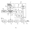
- FIG. 1 is a block diagram of an AM receiver embodying the invention in one form.
- master oscillator 18 in frequency synthesizer 17 is the source of a first reference-frequency signal which is coupled via lead 27 to programmable frequency divider 19.
- This divider can be programmed to provide, one at a time, local oscillator (LO) signal frequencies required by the receiver's frequency converter 12 to tune to signals from broadcast stations operating at assigned frequencies in the frequency band for which the receiver was designed.
- LO local oscillator
- the control signal from program source 24 to frequency divider 19 determines the frequency of the LO output signal from the divider on lead 29.
- Apparatus suitable for developing a programming control signal to divider 19 may be of several types. For example, it may be operated manually, as part of the receivers tuning apparatus, to tune incrementally from channel to channel. Alternatively, it may provide for automatically scanning up or down from one received station to another, or only to preselected stations. Combinations of these methods also may be used. Whichever method is used, apparatus 24, which controls divider 19 to make channel selection via converter 12, usually is also ganged with any tuning apparatus for the antenna 10 and/or radio-frequency (RF) circuits 11.
- RF radio-frequency
- Blocks 10 through 14 in Fig. 1 operate in the normal manner of a superheterodyne receiver.
- RF signals are picked up by antenna 10 and coupled to the RF circuits 11, which normally include bandpass filtering and amplification.
- frequency converter 12 the RF signal is converted to a corresponding IF signal, which is amplified in IF amplifier 13 and coupled to AM detector 14.
- the detected signal is then coupled via lead 15 to audio amplifiers, if required, and then to sound reproducing apparatus, such as loudspeakers.
- control unit 20 provides the functions required to develop a control signal which is coupled via lead 26, to master oscillator 18 to cause the master oscillator's first reference frequency on lead 27 to change in a direction which will prevent, reduce or eliminate a tweet which may occur when the received signal frequency is nominally an integral multiple of the IF.
- Programmable frequency divider 19 in addition to providing LO signals on lead 29 at the frequencies required by frequency converter 12, also develops a signal at a second reference frequency which is coupled, via lead 25, to phase-locked-loop (PLL) 21.
- the second reference frequency may be an integral submultiple of the IF, as in Fig. 1.
- the free-running frequency of the oscillator in PLL 21 is nominally equal to the IF, and the divisor (n) of divider 22 is an integer equal to the ratio of the nominal IF to the nominal second reference frequency.
- Such circuits are well known to those skilled in the art, and it will be recognized that the PLL oscillator will be locked to a frequency which is (n) times the second reference frequency.
- the output from PLL 12 is a signal at a third reference frequency which is coupled to phase detector 23 and to divider 22. Also coupled to the phase detector is the IF signal from the output of IF amplifier 13. Phase detector 23 develops a control signal which is representative of the difference in frequency between the third reference frequency signal from PLL 21 and the IF signal from IF amplifier 13.
- Master oscillator 18 is a stable, frequency-controlled oscillator (such as a voltage or current controlled oscillator).
- the control signal developed by phase detector 23 is coupled via lead 26 to the frequency-control input of the master oscillator, and thereby causes the master oscillator's first reference frequency output on lead 27 to change.
- the change in the first reference frequency will result in changes in the second reference frequency on lead 25 and in the frequency of the LO signal on lead 29.
- the third reference frequency from PLL 21 and the frequency of the IF signal on lead 16 will change in a direction which causes them to become equal in the preferred embodiment or very nearly equal in another embodiment. It will be shown that when the frequencies of these two signals become equal, the tweet frequency becomes zero.
- K1 and K2 are fixed constants, regardless of whether the invention is operative or not, and regardless of whether or not the signal and master oscillator frequencies have drifted from their specified values.
- K3 is a fixed integer only for the special conditions specified above for Column A, or, as will be shown mathematically below, when the invention is operative, as specified for Column C.
- K4 is a fixed constant only for the conditions specified for Columns A and C.
- K4 is the divisor (n) in divider 22 in Fig. 1.
- phase-detector 23 in the preferred embodiment of Fig. 1 acts in the normal manner to cause the third reference frequency from PLL 21 and the IF signal on lead 16 to lock at the same frequency.
- the control signal output from phase detector 23, on lead 26, contains a DC component, and until the two inputs to phase detector 23 become equal in frequency, an AC component is also present.
- the phase detector would be the equivalent of a frequency detector instead of a phase detector, and while the tweet frequency will be reduced, it will not necessarily become zero. This is so because the frequencies of the two input signals to phase detector 23 are not necessarily brought into a locked condition, and a small residual frequency difference may exist. However, the difference frequency will be small, and the tweet frequency will be in the subaudible range.
- the invention has been described in the environment of the AM receiver embodiment of Fig. 1, the invention is similarly applicable to the prevention, reduction or elimination of tweets in superheterodyne receivers for other frequency bands and modulation systems, including frequency modulation and video modulation.
- application of the principles of the invention is not restricted to the circuit of Fig. 1.
- a frequency synthesizer could be designed to provide a second reference frequency equal to the nominal IF frequency, thereby eliminating the need for PLL 21 and Divider 22 in Fig. 1.
- the essence of the invention is to develop a control signal which can be used in a manner that causes the tweet frequency to be reduced to zero in the preferred embodiment, or to a low-enough frequency to be inaudible, or at least less objectionable.
Landscapes
- Superheterodyne Receivers (AREA)
Priority Applications (2)
| Application Number | Priority Date | Filing Date | Title |
|---|---|---|---|
| EP88304422A EP0342277A1 (de) | 1988-05-16 | 1988-05-16 | Beseitigung oder Reduzierung von Gezwitscher in Überlagerungsempfängern |
| AU16349/88A AU603216B2 (en) | 1988-05-16 | 1988-05-17 | Tweet elimination, or reduction, in superheterodyne receivers |
Applications Claiming Priority (1)
| Application Number | Priority Date | Filing Date | Title |
|---|---|---|---|
| EP88304422A EP0342277A1 (de) | 1988-05-16 | 1988-05-16 | Beseitigung oder Reduzierung von Gezwitscher in Überlagerungsempfängern |
Publications (1)
| Publication Number | Publication Date |
|---|---|
| EP0342277A1 true EP0342277A1 (de) | 1989-11-23 |
Family
ID=8200068
Family Applications (1)
| Application Number | Title | Priority Date | Filing Date |
|---|---|---|---|
| EP88304422A Withdrawn EP0342277A1 (de) | 1988-05-16 | 1988-05-16 | Beseitigung oder Reduzierung von Gezwitscher in Überlagerungsempfängern |
Country Status (2)
| Country | Link |
|---|---|
| EP (1) | EP0342277A1 (de) |
| AU (1) | AU603216B2 (de) |
Citations (2)
| Publication number | Priority date | Publication date | Assignee | Title |
|---|---|---|---|---|
| US4451930A (en) * | 1982-08-02 | 1984-05-29 | Motorola Inc. | Phase-locked receiver with derived reference frequency |
| EP0196697A1 (de) * | 1985-03-11 | 1986-10-08 | Koninklijke Philips Electronics N.V. | AM-Empfänger |
Family Cites Families (3)
| Publication number | Priority date | Publication date | Assignee | Title |
|---|---|---|---|---|
| JPS5478009A (en) * | 1977-12-02 | 1979-06-21 | Sony Corp | Disturbing signal elimination unit |
| DD142974B1 (de) * | 1979-04-27 | 1984-11-07 | Eberhard Lemke | Schaltungsanordnung zur unterdrueckung von stoersignalen |
| FR2518852A1 (fr) * | 1981-12-18 | 1983-06-24 | Thomson Csf | Procede et dispositif electroniques de decouplage d'antenne |
-
1988
- 1988-05-16 EP EP88304422A patent/EP0342277A1/de not_active Withdrawn
- 1988-05-17 AU AU16349/88A patent/AU603216B2/en not_active Ceased
Patent Citations (2)
| Publication number | Priority date | Publication date | Assignee | Title |
|---|---|---|---|---|
| US4451930A (en) * | 1982-08-02 | 1984-05-29 | Motorola Inc. | Phase-locked receiver with derived reference frequency |
| EP0196697A1 (de) * | 1985-03-11 | 1986-10-08 | Koninklijke Philips Electronics N.V. | AM-Empfänger |
Non-Patent Citations (1)
| Title |
|---|
| REVIEW OF SCIENTIFIC INSTRUMENTS, vol. 53, no. 12, December 1982, pages 1894-1898, American Institute of Physics, New York, US; L. MUREDDU et al.: "Local area time dissemination by carrier-current waves" * |
Also Published As
| Publication number | Publication date |
|---|---|
| AU1634988A (en) | 1989-12-14 |
| AU603216B2 (en) | 1990-11-08 |
Similar Documents
| Publication | Publication Date | Title |
|---|---|---|
| US5307515A (en) | Adjacent channel controller for radio receiver | |
| US4451930A (en) | Phase-locked receiver with derived reference frequency | |
| US5311318A (en) | Double conversion digital tuning system using separate digital numbers for controlling the local oscillators | |
| CA2010176C (en) | Tuner station selecting apparatus | |
| JPS625381B2 (de) | ||
| EP0456099B1 (de) | Frequenzdemodulator für Frequenzsprungbetrieb mit Kanälen | |
| US4977613A (en) | Fine tuning frequency synthesizer with feedback loop for frequency control systems | |
| HK1008406B (en) | On channel agile fm demodulator | |
| US5203032A (en) | Station selecting apparatus | |
| GB2279519A (en) | Transmitter/receiver | |
| US4879757A (en) | Tweet elimination, or reduction, in superheterodyne receivers | |
| CA2118810C (en) | Radio having a combined pll and afc loop and method of operating the same | |
| US6091943A (en) | Combining oscillator with a phase-indexed control circuit for a radio receiver | |
| US4610030A (en) | Frequency modulated transmitter applicable to MF broadcasting | |
| US4245351A (en) | AFT Arrangement for a phase locked loop tuning system | |
| EP0342277A1 (de) | Beseitigung oder Reduzierung von Gezwitscher in Überlagerungsempfängern | |
| EP0519562B1 (de) | Empfänger mit einer Phasenregelschleife | |
| US6433830B1 (en) | Off-air phase lock technique | |
| JPS58205323A (ja) | シンセサイザ−受信機 | |
| US20050089119A1 (en) | Receiver | |
| JPH0254705B2 (de) | ||
| JPS60111535A (ja) | シンセサイザ受信機 | |
| JPH01320829A (ja) | スーパヘテロダイン受信機における有害な周波数関係を防止又は抑制する装置 | |
| JPS6322493B2 (de) | ||
| JPS5819172B2 (ja) | フアインチユ−ニング装置 |
Legal Events
| Date | Code | Title | Description |
|---|---|---|---|
| PUAI | Public reference made under article 153(3) epc to a published international application that has entered the european phase |
Free format text: ORIGINAL CODE: 0009012 |
|
| AK | Designated contracting states |
Kind code of ref document: A1 Designated state(s): DE FR GB IT NL |
|
| 17P | Request for examination filed |
Effective date: 19900314 |
|
| 17Q | First examination report despatched |
Effective date: 19921023 |
|
| STAA | Information on the status of an ep patent application or granted ep patent |
Free format text: STATUS: THE APPLICATION IS DEEMED TO BE WITHDRAWN |
|
| 18D | Application deemed to be withdrawn |
Effective date: 19930303 |