EP0342260A1 - Flexible coupling for an intermittent system such as a switch system - Google Patents
Flexible coupling for an intermittent system such as a switch system Download PDFInfo
- Publication number
- EP0342260A1 EP0342260A1 EP88108102A EP88108102A EP0342260A1 EP 0342260 A1 EP0342260 A1 EP 0342260A1 EP 88108102 A EP88108102 A EP 88108102A EP 88108102 A EP88108102 A EP 88108102A EP 0342260 A1 EP0342260 A1 EP 0342260A1
- Authority
- EP
- European Patent Office
- Prior art keywords
- shaft
- coupling according
- pin
- flex coupling
- axial
- Prior art date
- Legal status (The legal status is an assumption and is not a legal conclusion. Google has not performed a legal analysis and makes no representation as to the accuracy of the status listed.)
- Granted
Links
- 230000008878 coupling Effects 0.000 title claims abstract description 36
- 238000010168 coupling process Methods 0.000 title claims abstract description 36
- 238000005859 coupling reaction Methods 0.000 title claims abstract description 36
- 239000002184 metal Substances 0.000 claims description 7
- 239000011810 insulating material Substances 0.000 claims description 6
- 229910000831 Steel Inorganic materials 0.000 claims description 3
- 239000010959 steel Substances 0.000 claims description 3
- 238000006073 displacement reaction Methods 0.000 description 10
- 230000005540 biological transmission Effects 0.000 description 2
- 210000000078 claw Anatomy 0.000 description 2
- 230000001419 dependent effect Effects 0.000 description 2
- 230000000694 effects Effects 0.000 description 2
- 238000002955 isolation Methods 0.000 description 2
- 239000000314 lubricant Substances 0.000 description 2
- 238000004519 manufacturing process Methods 0.000 description 2
- 238000005299 abrasion Methods 0.000 description 1
- 238000009825 accumulation Methods 0.000 description 1
- 238000010276 construction Methods 0.000 description 1
- 239000013013 elastic material Substances 0.000 description 1
- 210000003746 feather Anatomy 0.000 description 1
- 239000004519 grease Substances 0.000 description 1
- 238000009413 insulation Methods 0.000 description 1
- 230000001050 lubricating effect Effects 0.000 description 1
- 239000000463 material Substances 0.000 description 1
- 230000035515 penetration Effects 0.000 description 1
- 238000004904 shortening Methods 0.000 description 1
- 238000003466 welding Methods 0.000 description 1
Images


Classifications
-
- F—MECHANICAL ENGINEERING; LIGHTING; HEATING; WEAPONS; BLASTING
- F16—ENGINEERING ELEMENTS AND UNITS; GENERAL MEASURES FOR PRODUCING AND MAINTAINING EFFECTIVE FUNCTIONING OF MACHINES OR INSTALLATIONS; THERMAL INSULATION IN GENERAL
- F16D—COUPLINGS FOR TRANSMITTING ROTATION; CLUTCHES; BRAKES
- F16D3/00—Yielding couplings, i.e. with means permitting movement between the connected parts during the drive
- F16D3/16—Universal joints in which flexibility is produced by means of pivots or sliding or rolling connecting parts
- F16D3/20—Universal joints in which flexibility is produced by means of pivots or sliding or rolling connecting parts one coupling part entering a sleeve of the other coupling part and connected thereto by sliding or rolling members
- F16D3/202—Universal joints in which flexibility is produced by means of pivots or sliding or rolling connecting parts one coupling part entering a sleeve of the other coupling part and connected thereto by sliding or rolling members one coupling part having radially projecting pins, e.g. tripod joints
- F16D3/205—Universal joints in which flexibility is produced by means of pivots or sliding or rolling connecting parts one coupling part entering a sleeve of the other coupling part and connected thereto by sliding or rolling members one coupling part having radially projecting pins, e.g. tripod joints the pins extending radially outwardly from the coupling part
- F16D3/2052—Universal joints in which flexibility is produced by means of pivots or sliding or rolling connecting parts one coupling part entering a sleeve of the other coupling part and connected thereto by sliding or rolling members one coupling part having radially projecting pins, e.g. tripod joints the pins extending radially outwardly from the coupling part having two pins
-
- H—ELECTRICITY
- H01—ELECTRIC ELEMENTS
- H01H—ELECTRIC SWITCHES; RELAYS; SELECTORS; EMERGENCY PROTECTIVE DEVICES
- H01H3/00—Mechanisms for operating contacts
- H01H3/32—Driving mechanisms, i.e. for transmitting driving force to the contacts
- H01H3/46—Driving mechanisms, i.e. for transmitting driving force to the contacts using rod or lever linkage, e.g. toggle
-
- H—ELECTRICITY
- H01—ELECTRIC ELEMENTS
- H01H—ELECTRIC SWITCHES; RELAYS; SELECTORS; EMERGENCY PROTECTIVE DEVICES
- H01H33/00—High-tension or heavy-current switches with arc-extinguishing or arc-preventing means
- H01H33/02—Details
- H01H33/022—Details particular to three-phase circuit breakers
-
- H—ELECTRICITY
- H01—ELECTRIC ELEMENTS
- H01H—ELECTRIC SWITCHES; RELAYS; SELECTORS; EMERGENCY PROTECTIVE DEVICES
- H01H3/00—Mechanisms for operating contacts
- H01H3/02—Operating parts, i.e. for operating driving mechanism by a mechanical force external to the switch
- H01H3/08—Turn knobs
- H01H3/10—Means for securing to shaft of driving mechanism
- H01H2003/105—Means for securing to shaft of driving mechanism with compensation of misalignment in the link between the operating part, the driving mechanism and the switch, e.g. misalignment between two axis
-
- H—ELECTRICITY
- H01—ELECTRIC ELEMENTS
- H01H—ELECTRIC SWITCHES; RELAYS; SELECTORS; EMERGENCY PROTECTIVE DEVICES
- H01H9/00—Details of switching devices, not covered by groups H01H1/00 - H01H7/00
- H01H2009/0088—Details of rotatable shafts common to more than one pole or switch unit
Definitions
- the invention relates to a flexible coupling (short: flex coupling) for intermittent operation, such as a switch drive, for connecting a first shaft (such as a switch shaft) to a second shaft, such as a drive shaft, the shaft axes being at an angle to one another (for example 0 ... 15 ° ) and u.
- a flexible coupling for intermittent operation, such as a switch drive, for connecting a first shaft (such as a switch shaft) to a second shaft, such as a drive shaft, the shaft axes being at an angle to one another (for example 0 ... 15 ° ) and u.
- U. can also have parallel displacement.
- Flex couplings for the connection of an input shaft to an output shaft, whereby the shaft axes can have an angle to one another and possibly also a parallel displacement have long been known in various forms.
- such couplings are realized for so-called claw coupling members for small angles, in which two mutually opposite coupling ends have tongue and groove arrangements which permit axial displacement as well as a slight angular deviation between the shaft axes.
- a disadvantage of this simple claw coupling is the fact that it is quite difficult to produce such couplings without torsional play. With many users such a small torsion play is irrelevant.
- the object of the invention is to create a flexible coupling of the type mentioned, which on the one hand enables largely play-free transmission of the rotary drive, but on the other hand can be manufactured relatively easily and in particular can also be assembled.
- the flexible coupling is said to be particularly suitable for the series connection of Numerous electrical switches, so that it is also required as part of the task that the flexible coupling can be further developed in a simple manner so that mutual isolation of the individual switch drive shafts is possible.
- the first shaft has a radial through-bore near its end with a pin arranged therein, preferably displaceably, the ends of which project beyond the circumferential surface of the shaft have flats lying parallel to one another
- the second shaft has an axial depression near its end, into which the end of the first shaft can be received, the axial depression having an inner cross section which widens from a narrowest cross section surrounding the first shaft with little play in both axial directions (e.g. hyperbolic) and thus pivots the allows the first shaft within the second shaft to a certain angle depending on the conical shape (z. B.
- the precision of the pivoting movement can be increased if the end faces of the pin ends in axial section View through the pin axis on a common circle, the diameter of which corresponds to the distance between the groove bases. In this way it is achieved that when the shaft axis is pivoted relative to one another, the end faces of the pin ends always rest largely without play on the groove bottoms.
- the part of the second shaft which has the axial depression is formed by a first sleeve made of metal, such as steel, which is rigidly connected to the remaining part of the second shaft.
- This connection can in particular represent a weld.
- the second shaft can in turn have a part made of insulating material, which is firmly enclosed by one end of a second sleeve made of metal, the other end of which is rigidly attached to the first sleeve, such as welded, soldered or glued, or is also integral with it. In this way, mutual isolation of the two shaft ends to be connected can be made possible in the simplest form, which can be advantageous in switch drive applications.
- the second sleeve can be connected to the insulating material shaft by means of dowel pins.
- the open end of the axial countersink of the second shaft is preferably covered with a rubber seal tightly surrounding the first shaft so that the penetration of dirt into the second area is avoided, on the other hand a lubricant can be introduced into the joint area without the risk that this lubricant undesirably emerges from the joint area.
- the part consisting of insulating material is linked on both sides to first and second sleeves and the first shaft is ver with a correspondingly shaped third shaft bound, so that there is a propeller shaft with doubled deflection ability, for example, two switches can be connected.
- a symmetrical cardan shaft can be achieved, which at one end in an output bearing, such as in a switch lever bearing, and at the other end in another such output bearing, or in an auxiliary bearing, or in a drive bearing, such as an electrical or pneumatic bearing or manually operated drive is stored.
- a flexible coupling 10 can be seen in a sectional view, which is to connect a first shaft 12 (e.g. it can be a switch shaft) with a second shaft 14 (e.g. drive shaft of a drive unit).
- the first shaft 12 is provided near its end with a radial through bore 16, in which a pin 18 is preferably slidably arranged, the ends 22, 24 of which protrude beyond the circumferential surface 20 of the shaft have parallel flats 26, for example manufactured by grinding the originally round end of the pin on two opposite sides.
- the two ends of the pin 18 each form a type of wedge or feather key with a spring width 28 or 30, which spring widths 28, 30 are preferably the same size, but need not necessarily be the same size.
- the second shaft 14 in turn has an axial depression 32 near its end, into which the end of the first shaft 12 can be received.
- the axial depression 32 has an internal cross section that is narrowest, the first shaft 12 only with a small radial clearance comprising cross-section 34 funnel-shaped in both axial directions, see reference number 36, so that a pivoting of the shaft 12 within the tube that forms the shaft 14 here by a maximum angle 38 is still possible, the size of this Angle 38 is dependent on the design of the funnel 36 and is 15 ° in the embodiment shown here.
- the section line 36 shown is not exactly the cross-sectional line because it is the edge of one of two grooves 40, which are arranged in the inner surface of the second shaft 14 at 180 ° circumferentially offset locations and parallel to the shaft axis 42 of the shaft 14 run. These grooves have a constant width 28 or 30 and, in contrast to the inner surface of the shaft 14, a constant depth of the bottom surfaces 44 from one another along the shaft axis 42. In these grooves, the flattened ends 22 and 24 of the pin 18 are slidably mounted and thus give the rotary connection between the two shafts, with simultaneous axial displacement and pivotability of the two shafts to each other by the angle 38, and parallel displacement of the shafts to be connected, if how In Fig. 1, the arrangement 10 is duplicated, see reference number 110.
- the end face 46 is curved, in such a way that in an axial sectional view through the pin axis ( corresponds here to the side view according to FIG. 1) these end faces 46 lie on a common circle (see its radius 48), the diameter (double radius 48) of which almost corresponds to the distance 44 between the two groove bases.
- the axial depression 32 has the shape of a first sleeve 50 made of metal, in particular steel, to which sleeve 50 a second sleeve 52 is attached respective ratios of adaptable length can be rigidly attached, for example by welding, see the weld seam 54.
- this further shaft part has the shape of a sleeve saves material on the one hand, which is important because this sleeve part 52 is intended to cross the longer distances in later use , which exist between two switches to be driven or a switch and a drive device.
- a first sleeve part 52 with a second sleeve part 152, which preferably consist of metal, in a simple manner by means of a cylindrical insulating piece 56 in such a way that insulation is created between these two metal parts 52, 152.
- the cylindrical insulating piece 56 is inserted into the sleeve ends and fixed by pinning by means of dowel pins 58.
- the sleeve 152 can be part of a flexible coupling 110, which may have an identical structure to the flexible coupling 10 already described.
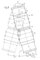
- an articulated shaft 60 is produced, as is shown again in a top view in FIG. 3, in which the axis 62 of the Shaft 12 can be pivoted by a maximum angle 38 with respect to the axis 42 of the shaft 52 or 152, while the shaft 112 can in turn be pivoted by an angle 138 with respect to the shaft 152, so that for this arrangement the permissible total angle of the pivoting is doubled and parallel displacement of the shafts to be connected is also made possible.
- the pin 18 is therefore expediently mounted in the bore 16 to better adapt it Allow ends on the groove bottoms. If such a precise adjustment is not necessary, the pin 18 could also be pressed into the bore 16, that is to say it cannot be axially displaceable.
- a rubber cover 64 which is designed and flexible so that it allows the movement of the shaft 12 in the direction of the angle 38, but on the other hand during this movement both tightly encloses the shaft 12 and also enables a tight connection with the annular end face 66 of the sleeve 50.
- the resulting closed cavity could also be filled with a lubricating grease so as to enable an abrasion-free movement between the flats 26 of the pin 18 on the one hand and the groove walls of the groove 40 on the other hand, as well as between the end faces 46 of the pin 18 and the bottom surfaces of the grooves 40 .
- abrasion between the shaft circumference of the shaft 12 and the conical section-like inner surfaces of the sleeve 50, which form the two funnels, is also depicted.
- FIG. 4 shows an application, wherein a pneumatic drive 68 is connected via two cardan shafts of the embodiment 60 shown in FIG. 1 to the drive rod 70 of a switch 72, not shown here, which switch 72 via a rail 74 with similar other switches is connected as shown in FIG. 5.
- the sleeves 52 of the individual flexible couplings have different lengths, cf. the sleeves with the reference numbers 152, 52, 252, 352.
- the shortening of the sleeves 52 and 152 is due to the interposition of the drive 68 between two switch groups, reference numbers 72, 172, while this drive between the switch groups 72 and 272 is omitted and therefore longer sleeves are used there.
- the distances 74 between the individual switch groups are chosen the same here and are, for example, of the order of 1.50 m.
- FIG. 5 is a section of a series arrangement of a total of 10 such switch groups, FIG. 5 showing the right end, while the left end is no longer shown with the remaining seven switch groups. At the left end, however, a drive similar to that between the switch groups 8 and 9 can be envisaged between the second and third switch groups, the drives 68 being operated by common pneumatic lines 76, 78.
Landscapes
- Engineering & Computer Science (AREA)
- General Engineering & Computer Science (AREA)
- Mechanical Engineering (AREA)
- Driving Mechanisms And Operating Circuits Of Arc-Extinguishing High-Tension Switches (AREA)
- Mechanisms For Operating Contacts (AREA)
- Flexible Shafts (AREA)
- Shafts, Cranks, Connecting Bars, And Related Bearings (AREA)
Abstract
Description
Die Erfindung betrifft eine flexible Kupplung (kurz: Flexkupplung) für intermittierenden Betrieb, wie Schalterantrieb, für die Verbindung einer ersten Welle (wie Schalterwelle) mit einer zweiten Welle, wie Antriebswelle, wobei die Wellenachsen zueinander einen Winkel (beispielsweise 0...15°) und u. U. auch Parallelverschiebung aufweisen können.The invention relates to a flexible coupling (short: flex coupling) for intermittent operation, such as a switch drive, for connecting a first shaft (such as a switch shaft) to a second shaft, such as a drive shaft, the shaft axes being at an angle to one another (for example 0 ... 15 ° ) and u. U. can also have parallel displacement.
Flexkupplungen für die Verbindung von einer Antriebswelle mit einer Abtriebswelle, wobei die Wellenachsen zueinander einen Winkel sowie möglicherweise auch eine Parallelverschiebung aufweisen können, sind in verschiedenster Form bereits seit langem bekannt. In ihrer einfachsten Form werden für kleine Winkel derartige Kupplungen durch sogenannte Klauenkupplungsglieder verwirklicht, bei der zwei sich gegenüberliegende Kupplungsenden Nut-Feder-Anordnungen aufweisen, die eine axiale Verschiebung wie auch eine geringfügige winkelmäßige Abweichung zwischen den Wellenachsen erlauben. Nachteilig an dieser einfachen Klauenkupplung ist die Tatsache, daß es recht schwierig ist, derartige Kupplungen ohne Torsionsspiel herzustellen. Bei vielen Anwen dungen ist ein derartiges geringes Torsionsspiel ohne Belang. Bei anderen Anwendungen, bei denen eine große Anzahl derartiger Kupplungen hintereinander angeordnet und mit einer entsprechenden Zahl von zu betreibenden Geräten, beispielsweise elektrischen Schaltern, verbunden werden, wobei an einem Ende dieser Anordnung ein Antriebsaggregat vorhanden ist, addieren sich bei einem vom Antrieb entfernt angeordneten Schalter zahlreiche derartige Spiele. Es kann daher vorkommen, daß ein entfernt angeordneter Schalter aufgrund des insgesamt zu hohen Spiels nicht mehr voll durchgeschaltet werden kann oder zumindest nur mit zeitlicher Verzögerung geschaltet wird, was von erheblichem Nachteil sein kann.Flex couplings for the connection of an input shaft to an output shaft, whereby the shaft axes can have an angle to one another and possibly also a parallel displacement, have long been known in various forms. In their simplest form, such couplings are realized for so-called claw coupling members for small angles, in which two mutually opposite coupling ends have tongue and groove arrangements which permit axial displacement as well as a slight angular deviation between the shaft axes. A disadvantage of this simple claw coupling is the fact that it is quite difficult to produce such couplings without torsional play. With many users such a small torsion play is irrelevant. In other applications, in which a large number of such couplings are arranged one behind the other and are connected to a corresponding number of devices to be operated, for example electrical switches, with a drive unit being present at one end of this arrangement, a switch arranged away from the drive adds up numerous such games. It can therefore happen that a switch located remotely can no longer be fully switched on due to the overall high clearance or is only switched with a time delay, which can be a considerable disadvantage.
Ähnliche Nachteile sind mit Flexkupplungen aus elastischem Material verbunden, bei denen die beiden Wellenenden z. B. über eine kräftige Spirale miteinander verbunden sind. Je nach Anzahl der Spiralwindungen sind unterschiedliche Winkelverlagerungen und Parallelverlagerungen zulässig. Nachteilig ist hier, daß neben der parallelen Verlagerung und der Winkelverlagerung auch ein belastungsabhängiges "Torsionsspiel" sich ergibt, das zwar klein gemacht werden kann, aber bei einer großen Anzahl von hintereinander geschalteten derartigen Kupplungen doch zu merklichen und störenden Answirkungen führt.Similar disadvantages are associated with flexible couplings made of elastic material, in which the two shaft ends, for. B. are connected by a strong spiral. Depending on the number of spiral turns, different angular misalignments and parallel misalignments are permitted. The disadvantage here is that, in addition to the parallel displacement and the angular displacement, there is also a load-dependent "torsion play" which, although it can be made small, leads to noticeable and disruptive effects with a large number of such couplings connected in series.
Weitgehend torsionsspielfrei sind Kreuzgelenke oder Kardangelenke. Ihre Nachteile sind aber der komplizierte Aufbau und die damit verbundenen hohen Fertigungskosten sowie die relativ umständliche Montage.Universal joints or universal joints are largely free of torsion play. However, their disadvantages are the complicated structure and the associated high manufacturing costs as well as the relatively cumbersome assembly.
Aufgabe der Erfindung ist die Schaffung einer Flexkupplung der eingangs genannten Art, die einerseits eine weitgehend spielfreie Drehantriebsweiterleitung ermöglicht, andererseits aber verhältnismäßig einfach hergestellt und insbesondere auch montiert werden kann. Die Flexkupplung soll insbesondere geeignet sein für die Reihenschaltung von zahlreichen elektrischen Schaltern, so daß auch als Teilaufgabe gefordert wird, daß die Flexkupplung in einfacher Weise so weiter ausgebildet werden kann, daß eine gegenseitige Isolation der einzelnen Schalterantriebswellen möglicht wird.The object of the invention is to create a flexible coupling of the type mentioned, which on the one hand enables largely play-free transmission of the rotary drive, but on the other hand can be manufactured relatively easily and in particular can also be assembled. The flexible coupling is said to be particularly suitable for the series connection of Numerous electrical switches, so that it is also required as part of the task that the flexible coupling can be further developed in a simple manner so that mutual isolation of the individual switch drive shafts is possible.
Gelöst wird die Aufgabe dadurch, daß die erste Welle nahe ihrem Ende eine Radialdurchgangsbohrung mit einem darin - vorzugsweise verschieblich - angeordneten Stift aufweist, dessen über die Wellenumfangsfläche hinausragenden Enden zueinander parallel liegende Abflachungen besitzen, und daß die zweite Welle nahe ihrem Ende eine Axialeinsenkung aufweist, in die das Ende der ersten Welle aufnehmbar ist, wobei die Axialeinsenkung einen inneren Querschnitt aufweist, der sich von einem engsten, die erste Welle mit geringem Spiel umschließenden Querschnitt sich in beide Axialrichtungen kegelschnittartig (z. B. hyperbolisch) erweitert und so eine Verschwenkung der ersten Welle innerhalb der zweiten Welle bis zu einem bestimmten, von der Kegelschnittform abhängigen Winkel (z. B. 15°) ermöglicht, und daß von dieser inneren Oberfläche der zweiten Welle zwei um 180° umfangsmäßig zueinander versetzte, zur Wellenachse der zweiten Welle parallel verlaufende Nuten konstanter Breite und konstanter Tiefe mit Bezug zueinander ausgehen, die die Stiftenden axial Verschieblich aufnehmen.The object is achieved in that the first shaft has a radial through-bore near its end with a pin arranged therein, preferably displaceably, the ends of which project beyond the circumferential surface of the shaft have flats lying parallel to one another, and that the second shaft has an axial depression near its end, into which the end of the first shaft can be received, the axial depression having an inner cross section which widens from a narrowest cross section surrounding the first shaft with little play in both axial directions (e.g. hyperbolic) and thus pivots the allows the first shaft within the second shaft to a certain angle depending on the conical shape (z. B. 15 °), and that from this inner surface of the second shaft two 180 ° circumferentially offset to each other, parallel to the shaft axis of the second shaft Grooves of constant width and constant T Ie go out with respect to each other, which receive the pin ends axially.
Durch diese Maßnahmen wird in verhältnismäßig einfacher Weise eine Flexkupplung geschaffen, die sowohl eine geringfügige axiale Verschiebung wie auch eine für die hier in Rede stehenden Anwendungsfälle ausreichende winkelmäßige Verschwenkung und Parallelverschiebung (bei doppelter Anordnung) der beiden miteinander zu verbindenden Wellen ermöglicht, andererseits aber eine praktisch torsionsspielfreie Drehübertragung ergibt.Through these measures, a flexible coupling is created in a relatively simple manner, which enables both a slight axial displacement and an angular pivoting and parallel displacement (with a double arrangement) of the two shafts to be connected, which is sufficient for the applications in question, but on the other hand a practical one torsion-free rotation transmission results.
Die Präzision der Verschwenkungsbewegung läßt sich vergrößern, wenn die Stirnflächen der Stiftenden in Axialschnitt ansicht durch die Stiftachse auf einem gemeinsamen Kreis liegen, dessen Durchmesser dem Abstand der Nutenböden entspricht. Auf diese Weise wird erreicht, daß bei Verschwenkung der Wellenachse zueinander die Stirnflächen der Stiftenden stets an den Nutenböden weitgehend spielfrei anliegen.The precision of the pivoting movement can be increased if the end faces of the pin ends in axial section View through the pin axis on a common circle, the diameter of which corresponds to the distance between the groove bases. In this way it is achieved that when the shaft axis is pivoted relative to one another, the end faces of the pin ends always rest largely without play on the groove bottoms.
Aus fertigungstechnischen Gründen und auch zur Erleichterung der Montage kann es günstig sein, wenn der die Axialeinsenkung aufweisende Teil der zweiten Welle von einer ersten Hülse aus Metall, wie Stahl, gebildet ist, der mit dem übrigen Teil der zweiten Welle starr verbunden ist. Diese Verbindung kann insbesondere eine Verschweißung darstellen. Die zweite Welle kann wiederum einen aus Isoliermaterial bestehenden Teil aufweisen, der von dem einen Ende einer zweiten Hülse aus Metall fest umschlossen ist, dessen anderes Ende an der ersten Hülse starr befestigt, wie angeschweißt, angelötet oder angeklebt oder auch mit dieser einstückig ist. Auf diese Weise läßt sich in einfachster Form eine gegenseitige Isolierung der beiden zu verbindenden Wellenenden ermöglichen, was bei Schalterantriebsanwendungen von Vorteil sein kann.For manufacturing reasons and also to facilitate assembly, it may be advantageous if the part of the second shaft which has the axial depression is formed by a first sleeve made of metal, such as steel, which is rigidly connected to the remaining part of the second shaft. This connection can in particular represent a weld. The second shaft can in turn have a part made of insulating material, which is firmly enclosed by one end of a second sleeve made of metal, the other end of which is rigidly attached to the first sleeve, such as welded, soldered or glued, or is also integral with it. In this way, mutual isolation of the two shaft ends to be connected can be made possible in the simplest form, which can be advantageous in switch drive applications.
Die zweite Hülse kann dabei mit der Isoliermaterialwelle mittels Spannstiften verbunden sein.The second sleeve can be connected to the insulating material shaft by means of dowel pins.
Das offene Ende der Axialeinsenkung der zweiten Welle ist vorzugsweise mit einer die erste Welle dicht umschließenden Gummidichtung abgedeckt, so daß das Eindringen von Schmutz in den zweiten Bereich vermieden wird, andererseits kann in den Gelenkbereich ein Schmiermittel eingebracht werden, ohne daß die Gefahr besteht, daß dieses Schmiermittel in ungewünschter Weise aus dem Gelenkbereich austritt.The open end of the axial countersink of the second shaft is preferably covered with a rubber seal tightly surrounding the first shaft so that the penetration of dirt into the second area is avoided, on the other hand a lubricant can be introduced into the joint area without the risk that this lubricant undesirably emerges from the joint area.
Gemäß einer noch anderen Ausführungsform der Erfindung ist das aus Isoliermaterial bestehende Teil beidseitig mit jeweils erster und zweiter Hülse verknüpft und die erste Welle mit einer entsprechenden geformten dritten Welle ver bunden, so daß sich eine Gelenkwelle mit verdoppelter Auslenkungsfähigkeit ergibt, mit der beispielsweise zwei Schalter verbunden werden können.According to yet another embodiment of the invention, the part consisting of insulating material is linked on both sides to first and second sleeves and the first shaft is ver with a correspondingly shaped third shaft bound, so that there is a propeller shaft with doubled deflection ability, for example, two switches can be connected.
Auf diese Weise läßt sich eine symmetrische Gelenkwelle erreichen, die an einem Ende in einem Abtriebslager, wie in einem Schalterhebellager, und am anderen Ende in einem weiteren derartigen Abtriebslager, oder in einem Hilfslager, oder aber in einem Antriebslager, wie Lager eines elektrischen oder pneumatischen oder handbetätigten Antriebs gelagert ist.In this way, a symmetrical cardan shaft can be achieved, which at one end in an output bearing, such as in a switch lever bearing, and at the other end in another such output bearing, or in an auxiliary bearing, or in a drive bearing, such as an electrical or pneumatic bearing or manually operated drive is stored.
Von besonderer Bedeutung ist eine Anwendung, bei der eine Reihe von nebeneinander im Abstand zueinander angeordneten Leistungsschaltern - Kurzschließern - jeweils von einer Gelenkwelle miteinander in mechanischer Verbindung stehen, wobei mindestens zwischen zwei derartigen Leistungsschalter anstelle einer Gelenkwelle ein Antriebsaggregat angeordnet ist. Bei Bedarf kann dieses Antriebsaggregat auch mit den jeweils benachbarten Schaltern über wiederum eine erfindungsgemäße Gelenkwelle mechanisch verbunden sein.Of particular importance is an application in which a number of circuit breakers arranged next to one another at a distance from one another - short-circuiters - are each mechanically connected by an articulated shaft, with a drive unit being arranged at least between two such circuit breakers instead of an articulated shaft. If necessary, this drive unit can also be mechanically connected to the respectively adjacent switches via a propeller shaft according to the invention.
Bei sehr langen Ketten von derartigen Leistungsschaltern kann es zweckmäßig sein, zwei Antriebsaggregate vorzusehen, die jeweils nahe einem der beiden Enden der Schalterkette angeordnet und gemeinsam pneumatisch, elektrisch oder auf sonstige Weise synchron angetrieben werden.In the case of very long chains of such circuit breakers, it may be expedient to provide two drive units, which are each arranged near one of the two ends of the switch chain and are driven synchronously pneumatically, electrically or in some other way.
Die Erfindung wird nachfolgend anhand von Ausführungsbeispielen näher erläutert, die in den Zeichnungen dargestellt sind.The invention is explained in more detail below on the basis of exemplary embodiments which are illustrated in the drawings.
Es zeigt:
- Fig. 1 in einer teilweise axial geschnittenen Ansicht eine Ausführungsform der erfindungsgemäßen Flexkupplung in Form einer Gelenkwelle;
- Fig. 2 eine Schnittansicht entlang der Linie II-II der Fig. 1;
- Fig. 3 eine Ansicht von außen auf die Anordnung gemäß Fig. 1;
- Fig. 4 ein Anwendungsbeispiel, wobei der zwei über ein isolierendes Wellenstück miteinander verbundene Gelenkwellen ein Verbindungsaggregat mit einem Schalterantrieb verkuppeln; und
- Fig. 5 eine ähnliche, jedoch verkleinerte Darstellung einer Anordnung gemäß Fig. 4, um darzustellen, wie weitere Schaltereinheiten hinzugefügt werden können.
- 1 is a partially axially sectioned view of an embodiment of the flexible coupling according to the invention in the form of an articulated shaft;
- Fig. 2 is a sectional view taken along the line II-II of Fig. 1;
- 3 is a view from the outside of the arrangement according to FIG. 1;
- Fig. 4 shows an application example, wherein the two cardan shafts connected to one another via an insulating shaft piece couple a connecting unit to a switch drive; and
- FIG. 5 is a similar, but scaled-down view of an arrangement according to FIG. 4, to show how further switch units can be added.
In Fig. 1 ist eine Flexkupplung 10 in einer Schnittdarstellung zu erkennen, die eine erste Welle 12 (z. B. kann es sich um eine Schalterwelle handeln) mit einer zweiten Welle 14 (z. B. Antriebswelle eines Antriebsaggregates) verbinden soll. Wie zu erkennen ist, ist die erste Welle 12 nahe ihrem Ende mit einer Radialdurchgangsbohrung 16 versehen, in der vorzugsweise verschieblich ein Stift 18 angeordnet ist, dessen über die Umfangsfläche 20 der Welle hinausragende Enden 22, 24 parallel zueinander liegende Abflachungen 26 aufweisen, beispielsweise hergestellt durch Abschleifen des ursprünglich runden Stiftendes an zwei sich gegenüberliegenden Seiten. Auf diese Weise bilden die beiden Enden des Stiftes 18 jeweils eine Art Keil oder Paßfeder mit einer Federbreite 28 bzw. 30, welche Federbreiten 28, 30 vorzugsweise gleich groß sind, aber nicht unbedingt gleich groß sein müssen.In Fig. 1, a
Die zweite Welle 14 wiederum besitzt nahe ihrem Ende eine Axialeinsenkung 32, in die das Ende der ersten Welle 12 aufnehmbar ist. Die Axialeinsenkung 32 besitzt einen Innenquerschnitt, der von einem engsten, die erste Welle 12 nur noch mit geringem Radialspiel umfassenden Querschnitt 34 nach beiden Axialrichtungen hin trichterförmig sich erweitert, siehe die Bezugszahl 36, so daß eine Verschwenkung der Welle 12 innerhalb des Rohres, das die Welle 14 hier bildet, um einen maximalen Winkel 38 noch ermöglicht wird, wobei die Größe dieses Winkels 38 von der Ausbildung des Trichters 36 abhängig ist und bei der hier dargestellten Ausführungsform 15° beträgt. Die dargestellte Schnittlinie 36 ist nicht genau die Querschnittslinie, weil es sich um die Kante einer von zwei Nuten 40 handelt, die in der inneren Oberfläche der zweiten Welle 14 an jeweils um 180° umfangsmäßig versetzten Stellen angeordnet sind und zur Wellenachse 42 der Welle 14 parallel verlaufen. Diese Nuten besitzen konstante Breite 28 bzw. 30 und im Gegensatz zur inneren Fläche der Welle 14 eine entlang der Wellenachse 42 konstante Tiefe Entfernung der Bodenflächen 44 zueinander. In diesen Nuten sind die angeflachten Enden 22 bzw. 24 des Stiftes 18 verschieblich gelagert und ergeben so die Drehverbindung zwischen den beiden Wellen, bei gleichzeitiger axialer Verschieblichkeit und Verschwenkbarkeit der beiden Wellen zueinander um den Winkel 38, und Parallelverschieblichkeit der zu verbindenden Wellen, wenn wie in Fig. 1, die Anordnung 10 doppelt vorhanden ist, siehe Bezugszahl 110.The
Um die Stirnenden des Stiftes 18 möglichst exakt in den beiden Nuten 40 mit geringem Spiel an den Bodenflächen 44 anliegend und trotzdem verschwenkbar und mit konstantem Spiel lagern zu können, ist die Stirnfläche 46 gekrümmt, und zwar derartig, daß in einer Axialschnittansicht durch die Stiftachse (entspricht hier der Seitenansicht gemäß Fig. 1) diese Stirnflächen 46 auf einem gemeinsamen Kreis (siehe dessen Radius 48) liegen, dessen Durchmesser (doppelter Radius 48) nahezu dem Abstand 44 der beiden Nutenböden entspricht.In order to be able to support the end faces of the
Es ist verhältnismäßig kompliziert, eine Welle mit einer Einsenkung 40 der beschriebenen Art zu versehen, insbeson dere wegen der sich ergebenden Hinterschneidung am inneren Ende dieser Einsenkung. Zweckmäßiger ist daher eine Konstruktion, wie sie auch bei der in Fig. 1 beschriebenen Ausführungsform gewählt wurde, bei der die Axialeinsenkung 32 die Form einer ersten Hülse 50 aus Metall, insbesondere aus Stahl hat, an welche Hülse 50 eine zweite Hülse 52 von an die jeweiligen Verhältnisse anpaßbarer Länge starr angebracht sein kann, beispielsweise durch Verschweißen, siehe die Schweißnaht 54. Dadurch, daß dieses weitere Wellenteil Hülsenform hat, wird zum einen Material eingespart, was deswegen bedeutungsvoll ist, weil dieses Hülsenteil 52 bei späterer Anwendung die größeren Strecken überqueren soll, die zwischen zwei anzutreibenden Schaltern oder einem Schalter und einer Antriebseinrichtung bestehen. Zum anderen ergibt sich die vorteilhafte Möglichkeit in einfacher Weise ein erstes Hülsenteil 52 mit einem zweiten Hülsenteil 152, die vorzugsweise aus Metall bestehen, mittels eines zylindrischen Isolierstückes 56 so zu verbinden, daß eine Isolierung zwischen diesen beiden Metallteilen 52, 152 entsteht. Das zylindrische Isolierstück 56 wird dabei in die Hülsenenden eingeschoben und durch Verstiftung mittels Spannstiften 58 festgelegt.It is relatively complicated to provide a shaft with a
Die Hülse 152 kann Teil einer Flexkupplung 110 sein, die identischen Aufbau haben mag, wie die bereits beschriebene Flexkupplung 10. Auf diese Weise entsteht eine Gelenkwelle 60, wie sie in Fig. 3 nochmals in einer Draufsicht dargestellt ist, bei der die Achse 62 der Welle 12 bezüglich der Achse 42 der Welle 52 bzw. 152 um einen maximalen Winkel 38 verschwenkt sein kann, während die Welle 112 bezüglich der Welle 152 wiederum um einen Winkel 138 verschwenkbar ist, so daß sich für diese Anordnung der zulässige Gesamtwinkel der Verschwenkung verdoppelt und außerdem Parallelverschiebung der zu verbindenden Wellen ermöglicht wird.The
Der Stift 18 ist deswegen zweckmäßigerweise in der Bohrung 16 verschieblichgelagert, um eine bessere Anpassung seiner Enden an die Nutenböden zu ermöglichen. Falls eine so genaue Anpassung nicht erforderlich ist, könnte der Stift 18 auch in die Bohrung 16 eingepreßt, also axial nicht verschieblich sein.The
Es ist zweckmäßig, den von der Axialeinsenkung 32 gebildeten Hohlraum, in dem sich die Gleitflächen zwischen dem Stift 18 und den Nutenböden und Wänden befinden, gegen Verschmutzungseinflüsse abzuschirmen, wozu hier eine Gummiabdeckung 64 dient, die so ausgestaltet und flexibel ist, daß sie die Bewegung der Welle 12 in Richtung des Winkels 38 ermöglicht, andererseits aber bei dieser Bewegung sowohl die Welle 12 dicht umschließt als auch eine dichte Verbindung mit der ringförmigen Stirnfläche 66 der Hülse 50 ermöglicht. Der dadurch gebildete abgeschlossene Hohlraum könnte zudem mit einem Schmierfett gefüllt werden, um so eine abriebfreie Bewegung zwischen den Abflachungen 26 des Stiftes 18 einerseits und den Nutwänden der Nut 40 andererseits wie auch zwischen den Stirnflächen 46 des Stiftes 18 und den Bodenflächen der Nuten 40 zu ermöglichen. Des weiteren wird auch der Abrieb zwischen dem Wellenumfang der Welle 12 und den kegelschnittartigen, die beiden Trichter bildenden Innenflächen der Hülse 50 abgebildet.It is expedient to shield the cavity formed by the
In Fig. 4 ist ein Anwendungsfall dargestellt, wobei ein pneumatischer Antrieb 68 über zwei Gelenkwellen der in Fig. 1 dargestellten Ausführungsform 60 mit der Antriebsstange 70 eines hier nicht näher dargestellten Schalters 72 verbunden ist, welcher Schalter 72 über eine Schiene 74 mit ähnlichen weiteren Schaltern in Verbindung steht, wie aus Fig. 5 hervorgeht. Wie in Fig. 5 zu erkennen ist, sind die Hülsen 52 der einzelnen Flexkupplungen unterschiedlich lang, vgl. die Hülsen mit den Bezugszahlen 152, 52, 252, 352. Die Verkürzung der Hülsen 52 und 152 ist bedingt durch die Zwischenschaltung des Antriebs 68 zwischen zwei Schaltergruppen, Bezugszahlen 72, 172, während dieser Antrieb zwischen den Schaltergruppen 72 bzw. 272 entfällt und daher dort längere Hülsen zur Anwendung gelangen. Die Abstände 74 zwischen den einzelnen Schaltergruppen sind hier gleich gewählt und betragen beispielsweise größenordnungsmäßig 1,50 m.4 shows an application, wherein a
Die Fig. 5 ist ein Ausschnitt aus einer Reihenanordnung von insgesamt 10 derartigen Schaltergruppen, wobei die Fig. 5 das rechte Ende wiedergibt, während das linke Ende mit den restlichen sieben Schaltergruppen nicht mehr dargestellt ist. Man kann sich am linken Ende aber ein zwischen der zweiten und dritten Schaltergruppe einen ähnlichen Antrieb vorgesehen denken, wie er hier zwischen den Schaltergruppen 8 und 9 angeordnet ist, wobei die Antriebe 68 durch gemeinsame Pneumatikleitungen 76, 78 betrieben werden. Die Anordnung läßt auch deutlich werden, daß der Antrieb wegen des langen Hebelarms 70 nur um ein geringes Winkelstück erfolgt, andererseits aber mit einem verhältnismäßig hohen Drehmoment, so daß es auf eine Flexkupplung ankommt, die auch nur geringes Winkelspiel vermeidet, da sonst an entfernt vom Antrieb 68 angebrachten Schalteinrichtungen (beispielsweise die Schalteinrichtungen 5 und 6) es zu Spielsummierungen käme, die möglicherweise zu einem Versagen des Ab- oder Anschaltens führen würde.FIG. 5 is a section of a series arrangement of a total of 10 such switch groups, FIG. 5 showing the right end, while the left end is no longer shown with the remaining seven switch groups. At the left end, however, a drive similar to that between the
Claims (11)
Priority Applications (3)
| Application Number | Priority Date | Filing Date | Title |
|---|---|---|---|
| AT88108102T ATE84127T1 (en) | 1988-05-20 | 1988-05-20 | FLEXIBLE COUPLING FOR INTERMITTENT SERVICE LIKE SWITCH DRIVE. |
| DE8888108102T DE3877188D1 (en) | 1988-05-20 | 1988-05-20 | FLEXIBLE COUPLING FOR INTERMITTENT OPERATION LIKE SWITCH DRIVE. |
| EP88108102A EP0342260B1 (en) | 1988-05-20 | 1988-05-20 | Flexible coupling for an intermittent system such as a switch system |
Applications Claiming Priority (1)
| Application Number | Priority Date | Filing Date | Title |
|---|---|---|---|
| EP88108102A EP0342260B1 (en) | 1988-05-20 | 1988-05-20 | Flexible coupling for an intermittent system such as a switch system |
Publications (2)
| Publication Number | Publication Date |
|---|---|
| EP0342260A1 true EP0342260A1 (en) | 1989-11-23 |
| EP0342260B1 EP0342260B1 (en) | 1992-12-30 |
Family
ID=8198989
Family Applications (1)
| Application Number | Title | Priority Date | Filing Date |
|---|---|---|---|
| EP88108102A Expired - Lifetime EP0342260B1 (en) | 1988-05-20 | 1988-05-20 | Flexible coupling for an intermittent system such as a switch system |
Country Status (3)
| Country | Link |
|---|---|
| EP (1) | EP0342260B1 (en) |
| AT (1) | ATE84127T1 (en) |
| DE (1) | DE3877188D1 (en) |
Cited By (5)
| Publication number | Priority date | Publication date | Assignee | Title |
|---|---|---|---|---|
| FR2719153A1 (en) * | 1994-04-21 | 1995-10-27 | Gec Alsthom T & D Sa | Joint between actuating rod of circuit breaker and control shaft |
| FR2725483A1 (en) * | 1994-10-07 | 1996-04-12 | Orain Michel | Assembly of homokinetic transmission joint for front wheel drive vehicles with high break out angles |
| EP0776020A1 (en) * | 1995-11-24 | 1997-05-28 | K.A. SCHMERSAL GmbH & Co. | Safety switch device |
| WO2002049055A1 (en) * | 2000-12-15 | 2002-06-20 | Siemens Aktiengesellschaft | Control shaft for actuating switching contacts of multipole electrical power circuit breakers |
| EP2467608A4 (en) * | 2009-08-21 | 2017-09-27 | Das Werk Pty Ltd | Rotor coupling |
Citations (6)
| Publication number | Priority date | Publication date | Assignee | Title |
|---|---|---|---|---|
| GB191003514A (en) * | 1908-03-20 | 1910-11-17 | William Ginns Bambridge | Improvements in or relating to Flexible Couplings. |
| DE412080C (en) * | 1924-04-16 | 1925-04-11 | Martin Rohde | Link chain, especially for speedometer drives |
| GB285663A (en) * | 1927-03-14 | 1928-02-23 | Nash Engineering Corp | Improvement in universal coupling |
| US1717729A (en) * | 1925-10-20 | 1929-06-18 | Herbert W Morreall | Gang-operated disconnecting switch |
| US3316367A (en) * | 1965-08-26 | 1967-04-25 | Mc Graw Edison Co | Reversible sectionalizing switch |
| US4114401A (en) * | 1977-01-24 | 1978-09-19 | Hoose William E Van | Universal joint embodying oscillating drive pin |
-
1988
- 1988-05-20 AT AT88108102T patent/ATE84127T1/en not_active IP Right Cessation
- 1988-05-20 DE DE8888108102T patent/DE3877188D1/en not_active Expired - Fee Related
- 1988-05-20 EP EP88108102A patent/EP0342260B1/en not_active Expired - Lifetime
Patent Citations (6)
| Publication number | Priority date | Publication date | Assignee | Title |
|---|---|---|---|---|
| GB191003514A (en) * | 1908-03-20 | 1910-11-17 | William Ginns Bambridge | Improvements in or relating to Flexible Couplings. |
| DE412080C (en) * | 1924-04-16 | 1925-04-11 | Martin Rohde | Link chain, especially for speedometer drives |
| US1717729A (en) * | 1925-10-20 | 1929-06-18 | Herbert W Morreall | Gang-operated disconnecting switch |
| GB285663A (en) * | 1927-03-14 | 1928-02-23 | Nash Engineering Corp | Improvement in universal coupling |
| US3316367A (en) * | 1965-08-26 | 1967-04-25 | Mc Graw Edison Co | Reversible sectionalizing switch |
| US4114401A (en) * | 1977-01-24 | 1978-09-19 | Hoose William E Van | Universal joint embodying oscillating drive pin |
Cited By (6)
| Publication number | Priority date | Publication date | Assignee | Title |
|---|---|---|---|---|
| FR2719153A1 (en) * | 1994-04-21 | 1995-10-27 | Gec Alsthom T & D Sa | Joint between actuating rod of circuit breaker and control shaft |
| FR2725483A1 (en) * | 1994-10-07 | 1996-04-12 | Orain Michel | Assembly of homokinetic transmission joint for front wheel drive vehicles with high break out angles |
| EP0776020A1 (en) * | 1995-11-24 | 1997-05-28 | K.A. SCHMERSAL GmbH & Co. | Safety switch device |
| US5896783A (en) * | 1995-11-24 | 1999-04-27 | K. A. Schmersal Gmbh & Co. | Safety switch device |
| WO2002049055A1 (en) * | 2000-12-15 | 2002-06-20 | Siemens Aktiengesellschaft | Control shaft for actuating switching contacts of multipole electrical power circuit breakers |
| EP2467608A4 (en) * | 2009-08-21 | 2017-09-27 | Das Werk Pty Ltd | Rotor coupling |
Also Published As
| Publication number | Publication date |
|---|---|
| EP0342260B1 (en) | 1992-12-30 |
| ATE84127T1 (en) | 1993-01-15 |
| DE3877188D1 (en) | 1993-02-11 |
Similar Documents
| Publication | Publication Date | Title |
|---|---|---|
| EP0164792B1 (en) | Device for the positive-drive connection of two shafts | |
| DE19521710B4 (en) | Panoramic head for optical devices, in particular for cameras | |
| DE2217309C3 (en) | Device for the transmission of a rotary movement | |
| DE3021156C2 (en) | Flexible coupling | |
| DE69110689T2 (en) | CARDAN JOINT FOR TOY CONSTRUCTION. | |
| DE3230932C2 (en) | coupling | |
| CH662621A5 (en) | SHAFT COUPLING. | |
| DE3334104C2 (en) | ||
| EP0342260B1 (en) | Flexible coupling for an intermittent system such as a switch system | |
| DE2318629A1 (en) | CENTERING DEVICE FOR SHAFT COUPLINGS OR DGL | |
| DE19919686A1 (en) | Flexible coupling with elastomer transmission belt | |
| EP0713023B1 (en) | Shaft coupling | |
| DE3220811C2 (en) | Pipe joint | |
| DE19816543C2 (en) | Motor drive with output shaft and corresponding coupling shell | |
| DE102021101986B4 (en) | Actuation device, lock cylinder, locking system and method | |
| DE4233382A1 (en) | Rotationally rigid torque-transferring coupling - has adjuster screws to tension slide guides and slide faces of coupling halves and centre piece relative to each other. | |
| DE8806631U1 (en) | Flexible coupling for intermittent operation, such as switch drive | |
| DE3606073A1 (en) | SWIVEL JOINT | |
| WO2023016782A1 (en) | Coupling device for a robot, coupling partial device therefore, and robot having a coupling device | |
| DE3543025A1 (en) | Mobile coupling | |
| EP1840397B1 (en) | Selector shaft for electrical switchgear | |
| DE3131694A1 (en) | "JOINT CLUTCH" | |
| DE4331699C2 (en) | Compensating coupling | |
| DE69306926T2 (en) | Shaft connection | |
| EP1161632B1 (en) | Coupling for linking two rotatable shaft ends |
Legal Events
| Date | Code | Title | Description |
|---|---|---|---|
| PUAI | Public reference made under article 153(3) epc to a published international application that has entered the european phase |
Free format text: ORIGINAL CODE: 0009012 |
|
| AK | Designated contracting states |
Kind code of ref document: A1 Designated state(s): AT BE CH DE ES FR GB GR IT LI LU NL SE |
|
| 17P | Request for examination filed |
Effective date: 19900516 |
|
| 17Q | First examination report despatched |
Effective date: 19910715 |
|
| GRAA | (expected) grant |
Free format text: ORIGINAL CODE: 0009210 |
|
| AK | Designated contracting states |
Kind code of ref document: B1 Designated state(s): AT BE CH DE ES FR GB GR IT LI LU NL SE |
|
| PG25 | Lapsed in a contracting state [announced via postgrant information from national office to epo] |
Ref country code: NL Effective date: 19921230 Ref country code: GR Free format text: LAPSE BECAUSE OF FAILURE TO SUBMIT A TRANSLATION OF THE DESCRIPTION OR TO PAY THE FEE WITHIN THE PRESCRIBED TIME-LIMIT Effective date: 19921230 Ref country code: GB Effective date: 19921230 Ref country code: FR Effective date: 19921230 Ref country code: ES Free format text: THE PATENT HAS BEEN ANNULLED BY A DECISION OF A NATIONAL AUTHORITY Effective date: 19921230 Ref country code: BE Effective date: 19921230 |
|
| REF | Corresponds to: |
Ref document number: 84127 Country of ref document: AT Date of ref document: 19930115 Kind code of ref document: T |
|
| REF | Corresponds to: |
Ref document number: 3877188 Country of ref document: DE Date of ref document: 19930211 |
|
| ITF | It: translation for a ep patent filed | ||
| PGFP | Annual fee paid to national office [announced via postgrant information from national office to epo] |
Ref country code: SE Payment date: 19930518 Year of fee payment: 6 |
|
| EN | Fr: translation not filed | ||
| PGFP | Annual fee paid to national office [announced via postgrant information from national office to epo] |
Ref country code: AT Payment date: 19930527 Year of fee payment: 6 |
|
| PG25 | Lapsed in a contracting state [announced via postgrant information from national office to epo] |
Ref country code: LU Free format text: LAPSE BECAUSE OF NON-PAYMENT OF DUE FEES Effective date: 19930531 |
|
| PGFP | Annual fee paid to national office [announced via postgrant information from national office to epo] |
Ref country code: CH Payment date: 19930609 Year of fee payment: 6 |
|
| NLV1 | Nl: lapsed or annulled due to failure to fulfill the requirements of art. 29p and 29m of the patents act | ||
| GBV | Gb: ep patent (uk) treated as always having been void in accordance with gb section 77(7)/1977 [no translation filed] |
Effective date: 19921230 |
|
| PLBE | No opposition filed within time limit |
Free format text: ORIGINAL CODE: 0009261 |
|
| STAA | Information on the status of an ep patent application or granted ep patent |
Free format text: STATUS: NO OPPOSITION FILED WITHIN TIME LIMIT |
|
| 26N | No opposition filed | ||
| PG25 | Lapsed in a contracting state [announced via postgrant information from national office to epo] |
Ref country code: AT Effective date: 19940520 |
|
| PG25 | Lapsed in a contracting state [announced via postgrant information from national office to epo] |
Ref country code: SE Effective date: 19940521 |
|
| PG25 | Lapsed in a contracting state [announced via postgrant information from national office to epo] |
Ref country code: LI Effective date: 19940531 Ref country code: CH Effective date: 19940531 |
|
| EUG | Se: european patent has lapsed |
Ref document number: 88108102.0 Effective date: 19941210 |
|
| REG | Reference to a national code |
Ref country code: CH Ref legal event code: PL |
|
| EUG | Se: european patent has lapsed |
Ref document number: 88108102.0 |
|
| PGFP | Annual fee paid to national office [announced via postgrant information from national office to epo] |
Ref country code: DE Payment date: 19980727 Year of fee payment: 11 |
|
| PG25 | Lapsed in a contracting state [announced via postgrant information from national office to epo] |
Ref country code: DE Free format text: LAPSE BECAUSE OF NON-PAYMENT OF DUE FEES Effective date: 20000301 |
|
| PG25 | Lapsed in a contracting state [announced via postgrant information from national office to epo] |
Ref country code: IT Free format text: LAPSE BECAUSE OF NON-PAYMENT OF DUE FEES;WARNING: LAPSES OF ITALIAN PATENTS WITH EFFECTIVE DATE BEFORE 2007 MAY HAVE OCCURRED AT ANY TIME BEFORE 2007. THE CORRECT EFFECTIVE DATE MAY BE DIFFERENT FROM THE ONE RECORDED. Effective date: 20050520 |