EP0342235B1 - Clamping mechanism of injection molding machines - Google Patents
Clamping mechanism of injection molding machines Download PDFInfo
- Publication number
- EP0342235B1 EP0342235B1 EP88902222A EP88902222A EP0342235B1 EP 0342235 B1 EP0342235 B1 EP 0342235B1 EP 88902222 A EP88902222 A EP 88902222A EP 88902222 A EP88902222 A EP 88902222A EP 0342235 B1 EP0342235 B1 EP 0342235B1
- Authority
- EP
- European Patent Office
- Prior art keywords
- cylinder
- clamping
- piston
- ram
- charge
- Prior art date
- Legal status (The legal status is an assumption and is not a legal conclusion. Google has not performed a legal analysis and makes no representation as to the accuracy of the status listed.)
- Expired - Lifetime
Links
Images

Classifications
-
- B—PERFORMING OPERATIONS; TRANSPORTING
- B29—WORKING OF PLASTICS; WORKING OF SUBSTANCES IN A PLASTIC STATE IN GENERAL
- B29C—SHAPING OR JOINING OF PLASTICS; SHAPING OF MATERIAL IN A PLASTIC STATE, NOT OTHERWISE PROVIDED FOR; AFTER-TREATMENT OF THE SHAPED PRODUCTS, e.g. REPAIRING
- B29C45/00—Injection moulding, i.e. forcing the required volume of moulding material through a nozzle into a closed mould; Apparatus therefor
- B29C45/17—Component parts, details or accessories; Auxiliary operations
- B29C45/64—Mould opening, closing or clamping devices
- B29C45/67—Mould opening, closing or clamping devices hydraulic
- B29C45/6764—Mould opening, closing or clamping devices hydraulic using hydraulically connectable chambers of the clamping cylinder during the mould opening and closing movement
- B29C45/6771—Mould opening, closing or clamping devices hydraulic using hydraulically connectable chambers of the clamping cylinder during the mould opening and closing movement the connection being provided within the clamping cylinder
-
- B—PERFORMING OPERATIONS; TRANSPORTING
- B22—CASTING; POWDER METALLURGY
- B22D—CASTING OF METALS; CASTING OF OTHER SUBSTANCES BY THE SAME PROCESSES OR DEVICES
- B22D17/00—Pressure die casting or injection die casting, i.e. casting in which the metal is forced into a mould under high pressure
- B22D17/20—Accessories: Details
- B22D17/26—Mechanisms or devices for locking or opening dies
-
- B—PERFORMING OPERATIONS; TRANSPORTING
- B29—WORKING OF PLASTICS; WORKING OF SUBSTANCES IN A PLASTIC STATE IN GENERAL
- B29C—SHAPING OR JOINING OF PLASTICS; SHAPING OF MATERIAL IN A PLASTIC STATE, NOT OTHERWISE PROVIDED FOR; AFTER-TREATMENT OF THE SHAPED PRODUCTS, e.g. REPAIRING
- B29C45/00—Injection moulding, i.e. forcing the required volume of moulding material through a nozzle into a closed mould; Apparatus therefor
- B29C45/17—Component parts, details or accessories; Auxiliary operations
- B29C45/76—Measuring, controlling or regulating
- B29C45/82—Hydraulic or pneumatic circuits
-
- B—PERFORMING OPERATIONS; TRANSPORTING
- B29—WORKING OF PLASTICS; WORKING OF SUBSTANCES IN A PLASTIC STATE IN GENERAL
- B29C—SHAPING OR JOINING OF PLASTICS; SHAPING OF MATERIAL IN A PLASTIC STATE, NOT OTHERWISE PROVIDED FOR; AFTER-TREATMENT OF THE SHAPED PRODUCTS, e.g. REPAIRING
- B29C45/00—Injection moulding, i.e. forcing the required volume of moulding material through a nozzle into a closed mould; Apparatus therefor
- B29C45/17—Component parts, details or accessories; Auxiliary operations
- B29C45/64—Mould opening, closing or clamping devices
- B29C45/67—Mould opening, closing or clamping devices hydraulic
- B29C2045/6785—Mould opening, closing or clamping devices hydraulic interconnecting two cylinders to supply fluid from one cylinder to the other during movement of the pistons
Definitions
- This invention relates to a clamping mechanism in an injection molding machine which is used to mold synthetic resins.
- a clamping mechanism As means for reducing a hydraulic resistance during opening and closing a mold, a clamping mechanism has been known from Japanese Patent Application Laid-Open No. 60-143915 in which an internal diameter of a front chamber of a cylinder is formed to be larger than an internal diameter of a rear chamber of the cylinder, and a pressure-oil flowing clearance is formed between the peripheral wall of the rear chamber of the cylinder and a piston.
- FR-A-2494628 shows a clamping mechanism which has two charge cylinders being parallelly mounted to a clamping cylinder.
- the charge cylinders communicate with the front chamber of the cylinder. They are provided with a piston rod operatively connected to the clamping ram of the clamping cylinder.
- a portion of the pressure oil is charged from the charge cylinders into the clamping cylinder during closing of the mold.
- the oil displaced by the movement of a piston in the clamping cylinder flows through the piston via a transfer conduit.
- a portion of the pressure oil is returned to a reservoir via a pipe.
- the transfer conduit can be closed by an annual piston working as a valve.
- Such a small-diameter transfer conduit has a high flow resistance for the pressure oil and therefore quick and smooth flow of the pressure oil from the front chamber to the rear chamber of the pressure cylinder is impossible.
- this invention overcomes the above-described problems encountered in prior art by the provision of a clamping mechanism comprising a clamping cylinder in which an internal diameter of a rear chamber of a cylinder is formed to be larger than an internal diameter of a front chamber of the cylinder, and a flowing clearance is formed between a peripheral wall of the rear chamber of the cylinder and a piston, and said piston having an external diameter adapted for the front chamber of the cylinder and having a front portion and a rear portion with a clamping ram and a booster ram made to be coaxial with each other, the improvement wherein a charge cylinder provided with a piston rod operatively connected to the clamping ram is provided parallel with the clamping ram on the side of said clamping cylinder, said charge cylinder being communicated with the front chamber of the cylinder, said charge cylinder having a charge area formed to be smaller than an end area of the clamping ram in the back of the piston, and a part of pressure oil within the cylinder is charged
- the high-speed advance is effected by pressure oil supplied into the cylinder via a passage and presssure oil from the charge cylinder, at which time oil pressure exerts on both surfaces of the piston, but since the outside diameter of the booster ram is smaller than the clamping ram, a pressure receiving surface of the back of the piston is larger than the front surface by an end area of the clamping ram, and the high-speed mold closing is effected by a differential pressure generated thereat.
- the charge area of the charge cylinder is formed to be smaller than the end area of the clamping ram to provide a difference of area therebetween, hydraulic resistance is not generated in the charge cylinder, and pressure oil in the charge cylinder is discharged into the clamping cylinder.
- the front end of the piston comes into contact with the front chamber of the cylinder, and the rear chamber of the cylinder is partitioned from the front chamber of the cylinder by the piston, after which pressure oil on the front chamber side of the cylinder together with pressure oil discharged out of the charge cylinder flows from the passage toward the rear chamber of the cylinder under the pressure on the rear chamber side of the cylinder to reduce the hydraulic resistance in the front chamber of the cylinder.
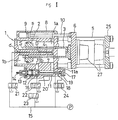
- FIG. 1 is a longitudinal sectional side view showing the state in which a mold is opened.
- reference numeral 1 designates a clamping cylinder, in which an internal diameter of a rear chamber 1b of a cylinder is formed to be larger than an internal diameter of a front chamber 1a of the cylinder.
- Reference numeral 2 designates a piston formed at the rear end of a clamping ram 3 and having an external diameter adapted for the front chamber 1a of the cylinder.
- a booster ram 4 projected in the central portion of the rear chamber 1b of the cylinder.
- Pressure receiving areas in front and rear surfaces of the piston 2 are larger in the rear surface by a portion of an end area S of the clamping ram 3 since an external diameter d of the booster ram 4 is smaller than an external diameter D of the clamping ram 3, and the clamping ram 3 is moved forward by a hydraulic force within the clamping cylinder due to a difference in area therebetween.
- the clamping ram 3 extends through a side wall of the cylinder and projected externally, and a movable plate 6 which is moved while being guided by a tie bar 5 is connected to the fore end of the clamping ram 3.
- the booster ram 4 has a hydraulic passage 7.
- Reference numeral 8 designates a charge cylinder, which is communicated with the front chamber 1a of the cylinder and is lined with the side of the clamping cylinder 1.
- a pressure receiving area that is, a charge area s of a charge piston 9 within the cylinder is formed to be smaller than the end area S of the clamping ram at the back surface of the piston 2, and a piston rod 10 is connected to the movable plate 6 along with the clamping ram 3.
- Reference numeral 11 designates a large-diameter passage provided on the side of the cylinder, which passage is provided over the front chamber 1a of the cylinder and a front portion of the rear chamber 1b of the cylinder, and the passage 11 has a passage 11a on the front chamber side of the cylinder and a passage 11b on the rear chamber side of the cylinder so that these passages 11a and 11b can be cut off by a valve member 12 provided on the passage 11b.
- the valve member 12 is always biased in a valve-closing direction by means of a spring member 13 to constitute a check valve, the spring member 13 capable of being suitably adjusted in pressure by means of a screw member 14.
- a flowing hole 16 for pressure oil from a hydraulic circuit 15 is bored in the side of the valve member 12.
- the valve member 12 is opened when pressure of the passage 11a on the front chamber side of the cylinder exceeds a spring pressure or by an operating device 17 provided opposedly of the valve member 12.
- the operating device 17 is composed of a hydraulic cylinder 18 and a rod 20 within a passage connected to a piston 19.
- the hydraulic circuit 15 is connected to the hydraulic circuit 7 of the booster ram 4, the passage 11 and the operating device 17 with switching valves 21, 22, 23 and 24 provided.
- reference numeral 25 designates a fixed plate
- 27 is a mold.
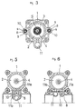
- the charge cylinder 8 is preferably lined on both sides of the clamping cylinder 1 as shown by a sectional view of FIG. 3, in which case, a charge area s (two such areas) need be made smaller than the end area S.
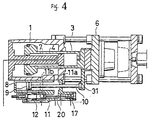
- Embodiments shown in FIGS. 4, 5 and 6 uses one charge cylinder 8 described above, which is provided underside of the clamping cylinder 1.
- the charge cylinder 8 and the pressure oil passage 11 are provided up and down, respectively, under the clamping cylinder 1, and a piston rod 10 is connected to an arm 31 projectd to the lower side at the fore end of the clamping ram 3.
- the passage 11a on the front chamber 1a side of the cylinder is made to serve as a passage to communicate the charge cylinder 8 with the front chamber 1a of the cylinder, and the passage 11b on the rear chamber 1b side of the cylinder is provided in the rear chamber 1b of the cylinder from both sides of the charge cylinder 8 as can seen in FIG. 5.
- FIG. 6 An embodiment shown in FIG. 6 is that the charge cylinder 8 and the passage 11 are provided in parallel with each other under the clamping cylinder 1.
- the valve member 12 when the operating device 17 is hydraulically actuated to return the rod 20 to its original position conversely to the former, the valve member 12 is returned to an equibrium position between the spring pressure and the oil pressure, whereby the passage 11 is drawn to slow-down the mold closing speed.
- the oil pressure is lowered and the valve member 12 cuts off the passage 11. Then, the rear chamber side of the cylinder is unilaterally pressurized to assume a clamping state.
- valve member 12 is opened to the FIG. 2 state for opening a mold, and the cylinder front chamber 1a and the cylinder rear chamber 1b are brought into communication with each other through the passage 11, after which pressure oil is supplied to the booster ram 4. Then, the clamping ram 3 along with the movable plate 6 moves backward at high speeds. At the same time, the piston rod 10 also moves backward, and pressure oil of the clamping cylinder 1 is taken into the charge cylinder 8 from the cylinder front chamber 1a. Pressure oil is then stored in the charge cylinder 8 for the succeeding high-speed mold closing.
- a charge cylinder in communication with a cylinder front chamber is provided on the side of a clamping cylinder, and a piston rod of the charge cylinder is moved along with the clamping cylinder so as to store a part of pressure oil within the clamping cylinder in the charge cylinder when a clamping ram advances whereas to discharge the pressure oil from the charge cylinder when the ram moves backward. Therefore, high-speed mold closing can be carried out without occurrence of cavitation merely by supplying a small quantity of pressure oil to the clamping cylinder.
- the charge cylinder is merely provided on the side to have the piston rod operatively connected to the clamping ram, and therefore, there has many merits as a clamping mechanism such as that the mechanism is simple in construction and particular operation is not necessary. Therefore, the clamping mechanism of this invention may be widely utilized in the molding industry for synthetic resins.
Landscapes
- Engineering & Computer Science (AREA)
- Mechanical Engineering (AREA)
- Manufacturing & Machinery (AREA)
- Moulds For Moulding Plastics Or The Like (AREA)
- Injection Moulding Of Plastics Or The Like (AREA)
Abstract
Description
- This invention relates to a clamping mechanism in an injection molding machine which is used to mold synthetic resins.
- As means for reducing a hydraulic resistance during opening and closing a mold, a clamping mechanism has been known from Japanese Patent Application Laid-Open No. 60-143915 in which an internal diameter of a front chamber of a cylinder is formed to be larger than an internal diameter of a rear chamber of the cylinder, and a pressure-oil flowing clearance is formed between the peripheral wall of the rear chamber of the cylinder and a piston.
- In the above-described clamping mechanism, the hydraulic resistance within the cylinder is reduced by the provision of the flowing clearance in the periphery of the piston, but a large quanity of pressure oil is required when a clamping ram is moved at high speeds, and since in a conventional pipe, its inlet and outlet for pressure oil is small in diameter, there gives rise to a problem in that in case of a large clamping mechanism, flowing-in-and-out of pressure oil during opening and closing of a mold lacks in smoothness, and high-speed opening and closing cannot be carried out.
- In view of the foregoing, the present inventor has developed means as disclosed in Japanese Patent Application No. 61-276185 previously filed, in which a front chamber of a cylinder and a rear chamber of the cylinder are communicated with each other through a large-diameter passage, a hydraulic circuit is connected to the rear chamber side of the cylinder of said passage and the front chamber side of the cylinder of the passage can be opened and closed by a valve, whereby pressure oil of the front chamber of the cylinder during opening and closing of a mold can be moved to the rear chamber of the cylinder through the passage, and even if a quantity of movement of pressure oil increases with the large-size of the clamping mechanism, the flowability of pressure oil is not impaired by the pipe resistance and the high-speed opening and closing can be carried out smoothly.
- By the means as described above, a trouble in flowing-in-and-out of pressure oil due to the pipe resistance has been obviated and the opening and closing of a mold has been made higher in speed than prior art, whilst a supply of pressure oil within the cylinder tends to be short by the high speed movement of the piston and a cavitation became liable to occur in the back of the piston, as a consequence of which there occurs the need to solve a new problem in that it takes time to increase pressure at the time of powerful clamping.
- While a short in the supply of pressure oil when a mold is closed can be solved by the provision of the supplying tank as in prior art, the operation of a valve opened and closed according to the movement of the piston is difficult, and in addition, the valve is complicated in construction and tends to produce a trouble.
- FR-A-2494628 shows a clamping mechanism which has two charge cylinders being parallelly mounted to a clamping cylinder. The charge cylinders communicate with the front chamber of the cylinder. They are provided with a piston rod operatively connected to the clamping ram of the clamping cylinder. A portion of the pressure oil is charged from the charge cylinders into the clamping cylinder during closing of the mold. The oil displaced by the movement of a piston in the clamping cylinder flows through the piston via a transfer conduit. A portion of the pressure oil is returned to a reservoir via a pipe. The transfer conduit can be closed by an annual piston working as a valve. Such a small-diameter transfer conduit has a high flow resistance for the pressure oil and therefore quick and smooth flow of the pressure oil from the front chamber to the rear chamber of the pressure cylinder is impossible.
- It is an object of this invention to provide an improved and new clamping mechanism which can charge a part of pressure oil within a cylinder according to a movement of a piston without requiring the operation, and which requires no particular power or operation to charge pressure oil.
- For achieving the aforesaid object, this invention overcomes the above-described problems encountered in prior art by the provision of a clamping mechanism comprising a clamping cylinder in which an internal diameter of a rear chamber of a cylinder is formed to be larger than an internal diameter of a front chamber of the cylinder, and a flowing clearance is formed between a peripheral wall of the rear chamber of the cylinder and a piston, and said piston having an external diameter adapted for the front chamber of the cylinder and having a front portion and a rear portion with a clamping ram and a booster ram made to be coaxial with each other, the improvement wherein a charge cylinder provided with a piston rod operatively connected to the clamping ram is provided parallel with the clamping ram on the side of said clamping cylinder, said charge cylinder being communicated with the front chamber of the cylinder, said charge cylinder having a charge area formed to be smaller than an end area of the clamping ram in the back of the piston, and a part of pressure oil within the cylinder is charged into said charge cylinder according to the movement of the clamping ram.
- In such a clamping mechanism, pressure oil flows into the cylinder chamber on the pressurized side from the flowing clearance as the piston moves. The high-speed withdrawal (mold opening) of the clamping ram is effected by the booster ram, at which time, a part of the pressure oil within the clamping cylinder is sucked into the charge cylinder. The high-speed advance (mold closing) is effected by pressure oil supplied into the cylinder via a passage and presssure oil from the charge cylinder, at which time oil pressure exerts on both surfaces of the piston, but since the outside diameter of the booster ram is smaller than the clamping ram, a pressure receiving surface of the back of the piston is larger than the front surface by an end area of the clamping ram, and the high-speed mold closing is effected by a differential pressure generated thereat.
- Furthermore, since the charge area of the charge cylinder is formed to be smaller than the end area of the clamping ram to provide a difference of area therebetween, hydraulic resistance is not generated in the charge cylinder, and pressure oil in the charge cylinder is discharged into the clamping cylinder. Moreover, the front end of the piston comes into contact with the front chamber of the cylinder, and the rear chamber of the cylinder is partitioned from the front chamber of the cylinder by the piston, after which pressure oil on the front chamber side of the cylinder together with pressure oil discharged out of the charge cylinder flows from the passage toward the rear chamber of the cylinder under the pressure on the rear chamber side of the cylinder to reduce the hydraulic resistance in the front chamber of the cylinder.
- When the piston moves from the front chamber of the piston and reaches a clamping position, the passage on the front chamber side of the cylinder is connected to a drain, and when the passage is cut off by a valve member to supply pressure oil to only the rear chamber side of the cylinder, pressure oil within the charge cylinder is switched to clamping as it is.
- The drawings schematically show a first embodiment of a clamping mechanism in an injection molding machine according to this invention, in which FIG. 1 is a longitudinal sectional side view showing the state in which a mold is opened.
- FIG. 2 is a longitudinal sectional side view showing the state in which a mold is closed.
- FIG. 3 is a longitudinal sectional end view showing essential parts.
- FIG. 4 is a longitudinal sectional side view showing the state in which a mold is opened according to a further embodiment.
- FIG. 5 is a longitudial sectional end view of FIG. 4.
- FIG. 6 is a longitudinal sectional end view showing another embodiment.
-
- In the figures,
reference numeral 1 designates a clamping cylinder, in which an internal diameter of arear chamber 1b of a cylinder is formed to be larger than an internal diameter of afront chamber 1a of the cylinder. -
Reference numeral 2 designates a piston formed at the rear end of aclamping ram 3 and having an external diameter adapted for thefront chamber 1a of the cylinder. Into the clampingram 3 is coaxially inserted abooster ram 4 projected in the central portion of therear chamber 1b of the cylinder. - Pressure receiving areas in front and rear surfaces of the
piston 2 are larger in the rear surface by a portion of an end area S of theclamping ram 3 since an external diameter d of thebooster ram 4 is smaller than an external diameter D of theclamping ram 3, and theclamping ram 3 is moved forward by a hydraulic force within the clamping cylinder due to a difference in area therebetween. - The
clamping ram 3 extends through a side wall of the cylinder and projected externally, and amovable plate 6 which is moved while being guided by atie bar 5 is connected to the fore end of theclamping ram 3. Thebooster ram 4 has ahydraulic passage 7. -
Reference numeral 8 designates a charge cylinder, which is communicated with thefront chamber 1a of the cylinder and is lined with the side of theclamping cylinder 1. A pressure receiving area, that is, a charge area s of acharge piston 9 within the cylinder is formed to be smaller than the end area S of the clamping ram at the back surface of thepiston 2, and apiston rod 10 is connected to themovable plate 6 along with theclamping ram 3. -
Reference numeral 11 designates a large-diameter passage provided on the side of the cylinder, which passage is provided over thefront chamber 1a of the cylinder and a front portion of therear chamber 1b of the cylinder, and thepassage 11 has apassage 11a on the front chamber side of the cylinder and apassage 11b on the rear chamber side of the cylinder so that thesepassages valve member 12 provided on thepassage 11b. - The
valve member 12 is always biased in a valve-closing direction by means of aspring member 13 to constitute a check valve, thespring member 13 capable of being suitably adjusted in pressure by means of ascrew member 14. A flowinghole 16 for pressure oil from ahydraulic circuit 15 is bored in the side of thevalve member 12. - The
valve member 12 is opened when pressure of thepassage 11a on the front chamber side of the cylinder exceeds a spring pressure or by anoperating device 17 provided opposedly of thevalve member 12. Theoperating device 17 is composed of ahydraulic cylinder 18 and arod 20 within a passage connected to apiston 19. - The
hydraulic circuit 15 is connected to thehydraulic circuit 7 of thebooster ram 4, thepassage 11 and theoperating device 17 withswitching valves - In the figures,
reference numeral 25 designates a fixed plate, and 27 is a mold. Thecharge cylinder 8 is preferably lined on both sides of theclamping cylinder 1 as shown by a sectional view of FIG. 3, in which case, a charge area s (two such areas) need be made smaller than the end area S. - Embodiments shown in FIGS. 4, 5 and 6 uses one
charge cylinder 8 described above, which is provided underside of theclamping cylinder 1. - In the embodiments shown in FIGS. 4 and 5, the
charge cylinder 8 and thepressure oil passage 11 are provided up and down, respectively, under theclamping cylinder 1, and apiston rod 10 is connected to anarm 31 projectd to the lower side at the fore end of theclamping ram 3. Thepassage 11a on thefront chamber 1a side of the cylinder is made to serve as a passage to communicate thecharge cylinder 8 with thefront chamber 1a of the cylinder, and thepassage 11b on therear chamber 1b side of the cylinder is provided in therear chamber 1b of the cylinder from both sides of thecharge cylinder 8 as can seen in FIG. 5. - An embodiment shown in FIG. 6 is that the
charge cylinder 8 and thepassage 11 are provided in parallel with each other under theclamping cylinder 1. - Next, the operation will be described.
- In the state in which a mold is opened shown in FIG. 1, when oil pressure is supplied to the cylinder
rear chamber 1b, a difference in pressure is generated due to the difference in the pressure receiving area between the front and rear surfaces of the piston and thepiston 2 is pressed towards thecylinder front chamber 1a. This pressure causes theclamping ram 5 to urge themovable plate 6 and moves forward, and at the same time, the pressing force is also applied to thepiston rod 10. Thecharge piston 9 integral with thepiston 2 moves forward, since the charge area s is smaller than the end area S in which pressure oil exerts on thepiston 2, along with thepiston 2 due to the difference in area therebetween, to discharge the pressure oil into thecylinder front chamber 1a. The thus discharged pressure oil along with the pressure oil which is present in a moving direction flows out towards the cylinderrear chamber 11b from the flowing clearance, comprising no hydraulic resistance. - When the front end of the
piston 2 reaches thecylinder front chamber 1a, as shown in FIG. 2, thepiston 2 is fitted into thecylinder front chamber 1a to lose the flowing clearance. However, at that time, when theoperating device 17 is actuated by oil pressure to advance therod 20 and move backward thevalve member 12 against thespring member 13 to open thepassage 11, thecylinder front chamber 1a comes into communication with the cylinderrear chamber 1b, and the pressure oil from thecharge cylinder 8 along with the pressure oil in thecylinder front chamber 1a flows out towards the cylinderrear chamber 1b, as a result of which no great resistance occurs in the oil pressure in thecylinder front chamber 1a. - Although not shown, when the
operating device 17 is hydraulically actuated to return therod 20 to its original position conversely to the former, thevalve member 12 is returned to an equibrium position between the spring pressure and the oil pressure, whereby thepassage 11 is drawn to slow-down the mold closing speed. At the time where the forward movement of thepiston 2 stops, when thepassage 11a on the front chamber side of the cylinder is connected to the drain by theswitching valve 22, the oil pressure is lowered and thevalve member 12 cuts off thepassage 11. Then, the rear chamber side of the cylinder is unilaterally pressurized to assume a clamping state. - After the completion of clamping, the
valve member 12 is opened to the FIG. 2 state for opening a mold, and thecylinder front chamber 1a and the cylinderrear chamber 1b are brought into communication with each other through thepassage 11, after which pressure oil is supplied to thebooster ram 4. Then, the clampingram 3 along with themovable plate 6 moves backward at high speeds. At the same time, thepiston rod 10 also moves backward, and pressure oil of theclamping cylinder 1 is taken into thecharge cylinder 8 from the cylinderfront chamber 1a. Pressure oil is then stored in thecharge cylinder 8 for the succeeding high-speed mold closing. - According to this invention, a charge cylinder in communication with a cylinder front chamber is provided on the side of a clamping cylinder, and a piston rod of the charge cylinder is moved along with the clamping cylinder so as to store a part of pressure oil within the clamping cylinder in the charge cylinder when a clamping ram advances whereas to discharge the pressure oil from the charge cylinder when the ram moves backward. Therefore, high-speed mold closing can be carried out without occurrence of cavitation merely by supplying a small quantity of pressure oil to the clamping cylinder. The charge cylinder is merely provided on the side to have the piston rod operatively connected to the clamping ram, and therefore, there has many merits as a clamping mechanism such as that the mechanism is simple in construction and particular operation is not necessary. Therefore, the clamping mechanism of this invention may be widely utilized in the molding industry for synthetic resins.
Claims (8)
- A clamping mechanism in an injection molding machine comprising a clamping cylinder (1) in which an internal diameter of a rear chamber (1b) of a cylinder is formed to be larger than an internal diameter of a front chamber (1a) of the cylinder, and a flowing clearance is formed between a peripheral wall of the rear chamber (1b) of the cylinder and a piston (2), and said piston (2) having a external diameter adapted for the front chamber (1a) of the cylinder and having a front portion and a rear portion with a clamping ram (3) and a booster ram (4) made to be coaxial with each other, characterized in that a charge cylinder (8) provided with a piston rod (10) operatively connected to the clamping ram (3) is provided parallel with the clamping ram (3) on the side of said clamping cylinder (1), said charge cylinder (8) being communicated with the front chamber (1a) of the cylinder, said charge cylinder (8) having a charge area (s) formed to be smaller than end area (S) of the clamping ram (3) in the back of the piston(2), and a part of pressure oil within the cylinder is charged into said charge cylinder (8) according to the movement of the clamping ram(3), said mechanism further comprises a large-diameter passage (11) provided on the side of the clamping cylinder (1) and provided over the front chamber (1a) and a front portion of the rear chamber (1b) of the clamping cylinder (1), a valve member (12) provided on the passage (11) to cut off the passage (11), said valve member (12) being always biased in a valve-closing direction by means of a spring member (13), and an operating device (17) provided opposedly of the valve member (12) and composed of a hydraulic cylinder to open the valve member (12).
- A clamping mechanism in an injection molding machine according to claim1, wherein said booster ram (4) is formed to be smaller in diameter than that of the clamping ram (3); said large-diameter passage (11) is provided over said front chamber (1a) of said cylinder and the rear chamber (1b) of said cylinder, a hydraulic circuit is connected to the rear chamber side of the cylinder of said passage (11), and a valve member (12) is provided to open and close the passage (11) on the front chamber side of the cylinder.
- A clamping mechanism in an injecion molding machine according to Claims 1 and 2, wherein said charge cylinder (8) is provided parallel with the clamping ram (3) on the side of the clamping cylinder (1), and a piston rod (10) of a charge piston (9) is connected to a movable plate (6) and moves along the clamping ram (3).
- A clamping mechanism in an injection molding machine according to Claim 1 and 2, wherein said charge cylinder (8) is mounted underside of the clamping cylinder (1).
- A clamping mechanism in an injection molding machine according to Claim 1, 2 and 3, wherein said piston rod (10) is connected to an arm (31) projected on the lower side at the fore end of the clamping ram (3) and moves along with the clamping ram (3).
- A clamping mechanism in an injection molding machine according to one of the prededing Claims, wherein the spring member (13) can be suitably adjusted in pressure by means of a screw member (14).
- A clamping mechanism in an injection molding machine according to one of the preceding Claims, wherein a flowing hole (16) for pressure oil from a hydraulic circuit (15) is bored in the side of the valve member (12).
- A Clamping mechanism in an injection molding machine according to one of the prededing Claims, wherein the operating device (17) is composed of a hydraulic cylinder (18) and a rod (20) within a passage connected to a piston (19).
Applications Claiming Priority (4)
| Application Number | Priority Date | Filing Date | Title |
|---|---|---|---|
| JP62045433A JPH068021B2 (en) | 1987-02-27 | 1987-02-27 | Clamping mechanism of injection molding machine |
| JP45433/87 | 1987-02-27 | ||
| JP4543387 | 1987-02-27 | ||
| PCT/JP1988/000217 WO1988006513A1 (en) | 1987-02-27 | 1988-02-27 | Clamping mechanism of injection molding machines |
Publications (3)
| Publication Number | Publication Date |
|---|---|
| EP0342235A1 EP0342235A1 (en) | 1989-11-23 |
| EP0342235A4 EP0342235A4 (en) | 1990-05-14 |
| EP0342235B1 true EP0342235B1 (en) | 1999-09-08 |
Family
ID=12719173
Family Applications (1)
| Application Number | Title | Priority Date | Filing Date |
|---|---|---|---|
| EP88902222A Expired - Lifetime EP0342235B1 (en) | 1987-02-27 | 1988-02-27 | Clamping mechanism of injection molding machines |
Country Status (7)
| Country | Link |
|---|---|
| US (1) | US4981426A (en) |
| EP (1) | EP0342235B1 (en) |
| JP (1) | JPH068021B2 (en) |
| KR (1) | KR950014776B1 (en) |
| AU (1) | AU1367388A (en) |
| DE (1) | DE3856361T2 (en) |
| WO (1) | WO1988006513A1 (en) |
Families Citing this family (47)
| Publication number | Priority date | Publication date | Assignee | Title |
|---|---|---|---|---|
| JPS6487318A (en) * | 1987-09-30 | 1989-03-31 | Nissei Plastics Ind Co | Mold clamping device |
| JP2832263B2 (en) * | 1989-10-30 | 1998-12-09 | 株式会社青木固研究所 | Rotary injection stretch blow molding machine |
| DE4018334C1 (en) * | 1990-06-08 | 1991-11-07 | Karl 7298 Lossburg De Hehl | Hydraulic appts. for mould closing unit of injection moulder - includes pump control valve on mould closure unit, hydraulic cylinder(s) controlled by 4-4 way valve |
| DE4340693C2 (en) * | 1993-11-30 | 1996-07-11 | Karl Hehl | Mold clamping unit for a plastic injection molding machine |
| DE19523420C1 (en) * | 1995-06-28 | 1996-09-12 | Boy Gmbh Dr | Injection moulding machine tool closure system with hydraulic pressure transmission unit |
| JP3262215B2 (en) * | 1997-08-18 | 2002-03-04 | 日精樹脂工業株式会社 | Mold clamping method of direct pressure mold clamping device |
| DE19835717A1 (en) * | 1998-08-07 | 2000-02-17 | Sms Eumuco Gmbh | Multi-cylinder metal bar extrusion press has filler bodies for press pistons to define storage areas in cylinder spaces, to accumulate oil displaced by pistons |
| ATE261348T1 (en) * | 2000-08-08 | 2004-03-15 | Bosch Rexroth Ag | DRIVE DEVICE, IN PARTICULAR FOR THE CLOSING UNIT, THE INJECTION UNIT OR THE EJECTOR OF A PLASTIC INJECTION MOLDING MACHINE |
| DE10051255C1 (en) * | 2000-10-16 | 2002-05-29 | Karl Hehl | Closure mechanism for a hydraulically operated plastics injection molding machine has tool closure, clamping and compensating cylinders concentric with a central axis |
| JP4548813B2 (en) * | 2000-12-04 | 2010-09-22 | 株式会社青木固研究所 | Hydraulic circuit of mold clamping device |
| DE10209921C1 (en) * | 2002-03-07 | 2003-10-30 | Karl Hehl | Locking device on a plastic injection molding machine |
| DE10215072A1 (en) | 2002-04-05 | 2003-10-30 | Billion Sa | Hydraulic device for moving a machine part back and forth |
| KR100571559B1 (en) * | 2003-03-29 | 2006-04-17 | 엘에스전선 주식회사 | High speed direct pressure clamping device |
| JP2004299269A (en) * | 2003-03-31 | 2004-10-28 | Aoki Technical Laboratory Inc | Mold clamping device |
| US7775966B2 (en) | 2005-02-24 | 2010-08-17 | Ethicon Endo-Surgery, Inc. | Non-invasive pressure measurement in a fluid adjustable restrictive device |
| US7658196B2 (en) | 2005-02-24 | 2010-02-09 | Ethicon Endo-Surgery, Inc. | System and method for determining implanted device orientation |
| US8016744B2 (en) | 2005-02-24 | 2011-09-13 | Ethicon Endo-Surgery, Inc. | External pressure-based gastric band adjustment system and method |
| US7699770B2 (en) | 2005-02-24 | 2010-04-20 | Ethicon Endo-Surgery, Inc. | Device for non-invasive measurement of fluid pressure in an adjustable restriction device |
| US7927270B2 (en) * | 2005-02-24 | 2011-04-19 | Ethicon Endo-Surgery, Inc. | External mechanical pressure sensor for gastric band pressure measurements |
| US8066629B2 (en) | 2005-02-24 | 2011-11-29 | Ethicon Endo-Surgery, Inc. | Apparatus for adjustment and sensing of gastric band pressure |
| US7775215B2 (en) | 2005-02-24 | 2010-08-17 | Ethicon Endo-Surgery, Inc. | System and method for determining implanted device positioning and obtaining pressure data |
| DE102005053802A1 (en) * | 2005-11-11 | 2007-05-16 | Demag Ergotech Gmbh | Closing device for an injection molding machine |
| US8152710B2 (en) * | 2006-04-06 | 2012-04-10 | Ethicon Endo-Surgery, Inc. | Physiological parameter analysis for an implantable restriction device and a data logger |
| US8870742B2 (en) | 2006-04-06 | 2014-10-28 | Ethicon Endo-Surgery, Inc. | GUI for an implantable restriction device and a data logger |
| US20080249806A1 (en) * | 2006-04-06 | 2008-10-09 | Ethicon Endo-Surgery, Inc | Data Analysis for an Implantable Restriction Device and a Data Logger |
| US20080250341A1 (en) * | 2006-04-06 | 2008-10-09 | Ethicon Endo-Surgery, Inc. | Gui With Trend Analysis for an Implantable Restriction Device and a Data Logger |
| US8187163B2 (en) * | 2007-12-10 | 2012-05-29 | Ethicon Endo-Surgery, Inc. | Methods for implanting a gastric restriction device |
| US8100870B2 (en) | 2007-12-14 | 2012-01-24 | Ethicon Endo-Surgery, Inc. | Adjustable height gastric restriction devices and methods |
| US8142452B2 (en) * | 2007-12-27 | 2012-03-27 | Ethicon Endo-Surgery, Inc. | Controlling pressure in adjustable restriction devices |
| US8377079B2 (en) | 2007-12-27 | 2013-02-19 | Ethicon Endo-Surgery, Inc. | Constant force mechanisms for regulating restriction devices |
| US20090171379A1 (en) * | 2007-12-27 | 2009-07-02 | Ethicon Endo-Surgery, Inc. | Fluid logic for regulating restriction devices |
| US8591395B2 (en) | 2008-01-28 | 2013-11-26 | Ethicon Endo-Surgery, Inc. | Gastric restriction device data handling devices and methods |
| US8192350B2 (en) | 2008-01-28 | 2012-06-05 | Ethicon Endo-Surgery, Inc. | Methods and devices for measuring impedance in a gastric restriction system |
| US8337389B2 (en) | 2008-01-28 | 2012-12-25 | Ethicon Endo-Surgery, Inc. | Methods and devices for diagnosing performance of a gastric restriction system |
| US20090192534A1 (en) * | 2008-01-29 | 2009-07-30 | Ethicon Endo-Surgery, Inc. | Sensor trigger |
| US20090204179A1 (en) * | 2008-02-07 | 2009-08-13 | Ethicon Endo-Surgery, Inc. | Powering implantable restriction systems using temperature |
| US7844342B2 (en) | 2008-02-07 | 2010-11-30 | Ethicon Endo-Surgery, Inc. | Powering implantable restriction systems using light |
| US8221439B2 (en) * | 2008-02-07 | 2012-07-17 | Ethicon Endo-Surgery, Inc. | Powering implantable restriction systems using kinetic motion |
| US8114345B2 (en) * | 2008-02-08 | 2012-02-14 | Ethicon Endo-Surgery, Inc. | System and method of sterilizing an implantable medical device |
| US8591532B2 (en) | 2008-02-12 | 2013-11-26 | Ethicon Endo-Sugery, Inc. | Automatically adjusting band system |
| US8057492B2 (en) * | 2008-02-12 | 2011-11-15 | Ethicon Endo-Surgery, Inc. | Automatically adjusting band system with MEMS pump |
| US8034065B2 (en) * | 2008-02-26 | 2011-10-11 | Ethicon Endo-Surgery, Inc. | Controlling pressure in adjustable restriction devices |
| US20090228063A1 (en) * | 2008-03-06 | 2009-09-10 | Ethicon Endo-Surgery, Inc. | System and method of communicating with an implantable antenna |
| US8233995B2 (en) | 2008-03-06 | 2012-07-31 | Ethicon Endo-Surgery, Inc. | System and method of aligning an implantable antenna |
| US8187162B2 (en) * | 2008-03-06 | 2012-05-29 | Ethicon Endo-Surgery, Inc. | Reorientation port |
| US9174111B2 (en) | 2012-07-06 | 2015-11-03 | Warrior Sports, Inc. | Protective athletic equipment |
| CN112706380B (en) * | 2021-01-20 | 2022-09-06 | 江门市百恊成塑料制品有限公司 | Stroke control structure for injection molding machine |
Family Cites Families (6)
| Publication number | Priority date | Publication date | Assignee | Title |
|---|---|---|---|---|
| FR2258949B3 (en) * | 1974-01-29 | 1977-10-21 | Tibor Szabo | |
| DE3044137C2 (en) * | 1980-11-24 | 1985-01-31 | Karl 7298 Loßburg Hehl | Mold clamping unit for receiving a plastic injection mold |
| DE3238111C1 (en) * | 1982-10-14 | 1984-03-29 | Karl 7298 Loßburg Hehl | Hydraulic device for the mold clamping unit of a plastic injection molding machine |
| JPS60143915A (en) * | 1983-12-30 | 1985-07-30 | Katashi Aoki | Clamping device of molding machine |
| JPS63128925A (en) * | 1986-11-19 | 1988-06-01 | Katashi Aoki | Mold clamping mechanism of injection molder |
| IN168838B (en) * | 1987-02-28 | 1991-06-22 | Nissei Plastics Ind Co |
-
1987
- 1987-02-27 JP JP62045433A patent/JPH068021B2/en not_active Expired - Fee Related
-
1988
- 1988-02-27 DE DE3856361T patent/DE3856361T2/en not_active Expired - Fee Related
- 1988-02-27 WO PCT/JP1988/000217 patent/WO1988006513A1/en not_active Ceased
- 1988-02-27 KR KR1019880701367A patent/KR950014776B1/en not_active Expired - Fee Related
- 1988-02-27 US US07/269,141 patent/US4981426A/en not_active Expired - Lifetime
- 1988-02-27 AU AU13673/88A patent/AU1367388A/en not_active Abandoned
- 1988-02-27 EP EP88902222A patent/EP0342235B1/en not_active Expired - Lifetime
Also Published As
| Publication number | Publication date |
|---|---|
| EP0342235A1 (en) | 1989-11-23 |
| DE3856361T2 (en) | 2000-03-23 |
| US4981426A (en) | 1991-01-01 |
| KR890700455A (en) | 1989-04-25 |
| DE3856361D1 (en) | 1999-10-14 |
| JPS63209916A (en) | 1988-08-31 |
| KR950014776B1 (en) | 1995-12-14 |
| AU1367388A (en) | 1988-09-26 |
| WO1988006513A1 (en) | 1988-09-07 |
| JPH068021B2 (en) | 1994-02-02 |
| EP0342235A4 (en) | 1990-05-14 |
Similar Documents
| Publication | Publication Date | Title |
|---|---|---|
| EP0342235B1 (en) | Clamping mechanism of injection molding machines | |
| KR920009273B1 (en) | Type fastening device | |
| KR920009275B1 (en) | Type fastening device | |
| JPH07214610A (en) | Ejector device of injection molding machine | |
| US7159639B2 (en) | Diecasting machine | |
| EP0309584A1 (en) | Clamping mechanism for injection molding machines | |
| US3916766A (en) | Control valve means for hydraulic press | |
| JPS6090728A (en) | Injection molding machine | |
| JPH0116591Y2 (en) | ||
| JPH0773787B2 (en) | Molding machine clamping device | |
| JPH1134132A (en) | Cylinder apparatus | |
| JPH0528027Y2 (en) | ||
| JPH01291917A (en) | Clamping mechanism for injection molding machine | |
| JPS6232817Y2 (en) | ||
| JPH0418815Y2 (en) | ||
| JPH0445866Y2 (en) | ||
| JPH07117090A (en) | Clamping device for injection molding machine | |
| JPH0428522B2 (en) | ||
| JP2808246B2 (en) | Mold clamping device of molding machine | |
| JPS6030036Y2 (en) | Mold clamping device for injection molding machine | |
| JPH04173303A (en) | Prefill valve for mold clamping device | |
| JPH0193324A (en) | Mold clamping device | |
| JPH01214420A (en) | Prefill valve with built-in pressure intensifying mechanism for clamping cylinder | |
| JPS6112316A (en) | Mold clamping mechanism | |
| JPH0671711A (en) | Mold clamper for injection molding machine or the like |
Legal Events
| Date | Code | Title | Description |
|---|---|---|---|
| PUAI | Public reference made under article 153(3) epc to a published international application that has entered the european phase |
Free format text: ORIGINAL CODE: 0009012 |
|
| 17P | Request for examination filed |
Effective date: 19890227 |
|
| AK | Designated contracting states |
Kind code of ref document: A1 Designated state(s): DE FR GB IT |
|
| A4 | Supplementary search report drawn up and despatched |
Effective date: 19900514 |
|
| DIN1 | Information on inventor provided before grant (deleted) | ||
| RIN1 | Information on inventor provided before grant (corrected) |
Inventor name: AOKI, KATASHI |
|
| RAP1 | Party data changed (applicant data changed or rights of an application transferred) |
Owner name: AOKI, KATASHI |
|
| RAP1 | Party data changed (applicant data changed or rights of an application transferred) |
Owner name: AOKI, KATASHI (DECEASED) |
|
| 19U | Interruption of proceedings before grant |
Effective date: 19920617 |
|
| 19W | Proceedings resumed before grant after interruption of proceedings |
Effective date: 19970821 |
|
| RAP1 | Party data changed (applicant data changed or rights of an application transferred) |
Owner name: AOKI, SHIGETO |
|
| 17Q | First examination report despatched |
Effective date: 19971002 |
|
| GRAG | Despatch of communication of intention to grant |
Free format text: ORIGINAL CODE: EPIDOS AGRA |
|
| GRAG | Despatch of communication of intention to grant |
Free format text: ORIGINAL CODE: EPIDOS AGRA |
|
| GRAH | Despatch of communication of intention to grant a patent |
Free format text: ORIGINAL CODE: EPIDOS IGRA |
|
| GRAH | Despatch of communication of intention to grant a patent |
Free format text: ORIGINAL CODE: EPIDOS IGRA |
|
| GRAA | (expected) grant |
Free format text: ORIGINAL CODE: 0009210 |
|
| AK | Designated contracting states |
Kind code of ref document: B1 Designated state(s): DE FR GB IT |
|
| ET | Fr: translation filed | ||
| REF | Corresponds to: |
Ref document number: 3856361 Country of ref document: DE Date of ref document: 19991014 |
|
| ITF | It: translation for a ep patent filed | ||
| PLBE | No opposition filed within time limit |
Free format text: ORIGINAL CODE: 0009261 |
|
| STAA | Information on the status of an ep patent application or granted ep patent |
Free format text: STATUS: NO OPPOSITION FILED WITHIN TIME LIMIT |
|
| 26N | No opposition filed | ||
| REG | Reference to a national code |
Ref country code: GB Ref legal event code: IF02 |
|
| PGFP | Annual fee paid to national office [announced via postgrant information from national office to epo] |
Ref country code: GB Payment date: 20060224 Year of fee payment: 19 |
|
| PGFP | Annual fee paid to national office [announced via postgrant information from national office to epo] |
Ref country code: IT Payment date: 20060228 Year of fee payment: 19 |
|
| PGFP | Annual fee paid to national office [announced via postgrant information from national office to epo] |
Ref country code: DE Payment date: 20060309 Year of fee payment: 19 |
|
| PGFP | Annual fee paid to national office [announced via postgrant information from national office to epo] |
Ref country code: FR Payment date: 20060322 Year of fee payment: 19 |
|
| GBPC | Gb: european patent ceased through non-payment of renewal fee |
Effective date: 20070227 |
|
| REG | Reference to a national code |
Ref country code: FR Ref legal event code: ST Effective date: 20071030 |
|
| PG25 | Lapsed in a contracting state [announced via postgrant information from national office to epo] |
Ref country code: DE Free format text: LAPSE BECAUSE OF NON-PAYMENT OF DUE FEES Effective date: 20070901 |
|
| PG25 | Lapsed in a contracting state [announced via postgrant information from national office to epo] |
Ref country code: GB Free format text: LAPSE BECAUSE OF NON-PAYMENT OF DUE FEES Effective date: 20070227 Ref country code: FR Free format text: LAPSE BECAUSE OF NON-PAYMENT OF DUE FEES Effective date: 20070228 |
|
| PG25 | Lapsed in a contracting state [announced via postgrant information from national office to epo] |
Ref country code: IT Free format text: LAPSE BECAUSE OF NON-PAYMENT OF DUE FEES Effective date: 20070227 |