EP0342020A2 - Method and apparatus for continuous strip casting - Google Patents
Method and apparatus for continuous strip casting Download PDFInfo
- Publication number
- EP0342020A2 EP0342020A2 EP89304760A EP89304760A EP0342020A2 EP 0342020 A2 EP0342020 A2 EP 0342020A2 EP 89304760 A EP89304760 A EP 89304760A EP 89304760 A EP89304760 A EP 89304760A EP 0342020 A2 EP0342020 A2 EP 0342020A2
- Authority
- EP
- European Patent Office
- Prior art keywords
- cooling wall
- strip
- oscillating
- zone
- metal
- Prior art date
- Legal status (The legal status is an assumption and is not a legal conclusion. Google has not performed a legal analysis and makes no representation as to the accuracy of the status listed.)
- Withdrawn
Links
Images


Classifications
-
- B—PERFORMING OPERATIONS; TRANSPORTING
- B22—CASTING; POWDER METALLURGY
- B22D—CASTING OF METALS; CASTING OF OTHER SUBSTANCES BY THE SAME PROCESSES OR DEVICES
- B22D11/00—Continuous casting of metals, i.e. casting in indefinite lengths
-
- B—PERFORMING OPERATIONS; TRANSPORTING
- B22—CASTING; POWDER METALLURGY
- B22D—CASTING OF METALS; CASTING OF OTHER SUBSTANCES BY THE SAME PROCESSES OR DEVICES
- B22D11/00—Continuous casting of metals, i.e. casting in indefinite lengths
- B22D11/04—Continuous casting of metals, i.e. casting in indefinite lengths into open-ended moulds
- B22D11/053—Means for oscillating the moulds
- B22D11/0535—Means for oscillating the moulds in a horizontal plane
-
- B—PERFORMING OPERATIONS; TRANSPORTING
- B22—CASTING; POWDER METALLURGY
- B22D—CASTING OF METALS; CASTING OF OTHER SUBSTANCES BY THE SAME PROCESSES OR DEVICES
- B22D11/00—Continuous casting of metals, i.e. casting in indefinite lengths
- B22D11/14—Plants for continuous casting
Definitions
- This invention relates generally to a method and apparatus for producing thin steel slabs and strip, and has to do particularly with a process by which such materials can be directly cast.
- One conventional method of making steel strip is to use the well known continuous casting process to make slabs which may typically be 200 mm to 250 mm thick. These slabs are then put through a hot strip mill where they are rolled down to a thickness of typically 1.8 to 4.8 mm, whereupon they are passed through a cold finishing mill to achieve the final thickness.
- a significant departure from the twin roll casting concept is represented by Japanese patent application 2230458, assigned to Nippon Steel Corp.
- a container with an open top is defined by a sloping bottom wall and a weir (lateral wall) extending around three sides.
- the bottom wall is water-cooled and receives the input of high-frequency vibratory energy to reduce friction.
- Hot metal is poured into the basin so defined, and solidifies as a layer against the cooled bottom wall. This layer is then withdrawn through the missing fourth wall, coming off as a strip which passes between one or more pairs of nip rollers.
- a major disadvantage of this Japanese development is the fact that the melt has its top surface exposed to the air. Moreover, in the region where the strip is exiting from the continuous casting mold, the upper surface of the molten steel literally "becomes" the top surface of the final cast product. This is very disadvantageous due to the fact that the upper surface of the melt tends to become covered with slag, flux or oxides which are undesirable as inclusions in the top surface of the finished strip. Additionally there are certain fluid flow problems associated with trying to cast from a liquid surface, problems that can contribute to a rough (wavy) solidified surface.
- this invention provides an apparatus for the manufacture of metal strip, comprising: a primary solidification zone in the form of a chamber for containing molten metal, the chamber being defined in part by an oscillating cooling wall upon which solidification of the molten metal can take place, thus creating one face of the metal strip, first cooling means for withdrawing heat from said cooling wall, a secondary solidification zone adjoining the primary solidification zone and adapted to receive solidified metal from said primary zone, the secondary solidification zone being defined in part by a further cooling wall facing oppositely from said oscillating cooling wall, whereby solidification of the molten metal can take place against the further cooling wall to create a second face of the metal strip, the secondary solidification zone including means for maintaining the metal strip juxtaposed against said further cooling wall, second cooling means for withdrawing heat from said further cooling wall, and extracting means for withdrawing the metal strip from said primary zone through said secondary zone.
- this invention provides a method for the continuous manufacture of metal strip at or near the desired final thickness, the method comprising the steps: metering molten metal into a primary solidification zone in the form of a chamber, the chamber being defined in part by a cooling wall, withdrawing heat from said cooling wall so that the metal solidifies in a layer against the cooling wall, thus creating one face of the metal strip, oscillating said cooling wall to discourage the solidified metal from adhering to the cooling wall, passing the layer of solidified metal into a secondary solidification zone adjoining the primary solidification zone, the secondary solidification zone being defined in part by a further cooling wall facing oppositely from said first-mentioned cooling wall, so that solidification of the molten metal takes place against the further cooling wall to create a second face of the metal strip, maintaining the metal strip juxtaposed against said further cooling wall to avoid break-out of molten metal from said chamber, and withdrawing the metal strip from said secondary zone.
- Figure 1 shows a ladle 10 delivering molten steel to a tundish 12. From the tundish 12 the molten steel passes to a strip casting mold 14 which will be described in greater detail later in this specification.
- the strip casting mold 14 continuously casts a steel strip which passes through a housing 16, and then through a plurality of rollers 18 which re-direct the strip into a horizontal direction.
- a laminar spray cooling mechanism 20 is provided to reduce the temperature of the strip, and finally the strip is coiled in a coiling facility 22.
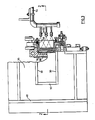
- Figure 2 illustrates the details of construction for one embodiment of a strip casting mold 14.
- An internal chamber 24 has an open top end 26, and is defined between a substantially vertical face 28, substantially vertical insulating side walls 30 (only one seen in the sectional view of Figure 2), and an insulating oblique wall 32. Near the top of the mold 14, the oblique wall 32 joins a short vertical wall 34.
- the walls 32 and 34 are surfaces of a monolithic refractory block 36 which is held in place by frame members 38, bottom support panel 39, and vertical panel 40.
- the vertical face 28, in the embodiment illustrated, is the inside face of a panel 43 which is preferably of high-conductivity copper.
- the panel 43 constitutes a cooling wall which is coated with boron nitride due to the "slippery" nature of this material with respect to solidified steel. While boron nitride is considered to be a preferred low-friction material that could be advantageously used in this invention, it is emphasized that other materials with similar properties could be selected, and the present invention should not be considered limited to this particular material.
- the panel 43 is part of a complex geometry which includes horizontal integral fins 50.
- the fins 50 are spaced apart vertically, and define chambers into which cooling water can be sprayed from a plurality of appropriately positioned nozzles 52 connected to pipes 54.
- the complex of which panel 43 forms a part includes side walls 56 (only one being seen in the vertical sectional view of Figure 2).
- the panel 43 does not extend the full height of the wall.
- the panel 43 is connected to a top wall 60 which defines the bottom extremity of an insulation chamber 62 in which insulation is provided.
- the top of the chamber 62 is defined by a plate 64.
- the insulation provided in chamber 62 may be alumina or an alumina-graphite composite. Such insulation may be coated on the inside face 65a with a material such as zirconia (Zr2O3).
- Panel 43 is integral at the bottom with a flange 60a that rests on a plate 64a. Structures 65 are shown schematically to represent support means for the strip caster.
- the intended level for the molten steel is at the line 66, this line being above the upper wall 60 of the cooling unit.
- the upper layers of the melt remain at a high temperature and do not contribute material to the forming strip.
- the solidification thus begins at some chosen depth below the surface of the melt but still proceeds against a continuous integral face.
- a further cooling wall 68 spaced leftwardly away from the surface of the bottom portion of the panel 43.
- the forming steel strip will be withdrawn through the gap between these two portions.
- a typical gap may be in the region of 12 mm.
- the wall 68 is C-shaped in section, and cooperates with a vertical panel 69 to define a water chamber 70, fed through pipes 72 and 74.
- the wall 68 may also have a boron nitride or equivalent coating 76 which is intended to reduce friction with the strip.
- the provision of the chamber 24 is of advantage in that 1) it allows the use of conventional feed means such as nozzles, and 2) it promotes stabilization of the melt temperature.
- first solidification zone extending from the level of the upper wall 60 (at the top of the panel 43) down to the level of the bottom of the refractory block 36
- second solidification zone extending below the first solidification zone as far as the bottom of the further cooling wall 68.
- the rightward face of the ultimate strip is formed against the vertical face 28 of the panel 43 in the first solidification zone
- the leftward face of the ultimate strip is formed against the further cooling wall 68 in the secondary solidification zone.
- Figure 7 is a schematic vertical sectional view of another embodiment of this invention, somewhat distorted in terms of the strip thickness in order that the process of strip solidification can be better understood.
- a chamber 224 is shown to be defined in part between a sloping insulating wall 232 and a vertical cooling wall 228, the latter being of high-conductivity copper coated with boron nitride.
- the cooling wall 228, against which water jets 252 are directed, has a cooling effect only up to its top flange 260.
- the numeral 262 identifies insulating material above the cooling wall 228, thus ensuring that slag and impurities at the surface of the melt will not be drawn into the forming strip.
- the first solidification zone is encompassed by the bracket 245, which in this embodiment extends only to the bottom of the cooling wall 228.
- the secondary solidification zone extends as far as the bottom of a cooling unit 268, the construction of which would be the same as that shown at 68, 69 and 70 in Figure 2.
- the secondary solidification zone is encompassed by the bracket 247.
- the thickness of the forming strip is exaggerated. As can be seen by the profile 270, the strip progressively increases in thickness in the downward direction within the first solidification zone 245, due to the cooling effect of the cooling wall 228. Once the strip has left the first solidification zone, however, the increase in thickness from the right side proceeds at a very reduced rate. Within the secondary solidification zone, the cooling effect of the unit 268 causes solidification to proceed from the left side, rapidly increasing in thickness until the entire strip is solid. Solidification is preferably completed within the secondary solidification zone 247. In a preferred embodiment, the unit 268 undergoes oscillation which may be horizontally parallel to the strip, or vertically, or a combination of these motions.
- shrinkage cavities or voids 271 will occur along the interior plane where the two solidification fronts come together.
- these voids are welded together (eliminated) by withdrawing the formed strip 273 using extraction rolls 275 which not only pinch and pull the strip 273 downwardly, but also reduce its thickness.
- the pressure applied to achieve thickness reduction can be adjusted to weld up any contained voids 271.
- back-up rolls could be used to reduce any tendency for the strip to develop a crown as a result of the thickness reduction process.
- the rolls 275 serve several purposes: 1) they weld up the voids, as already stated, 2) they planish the surface to make it smoother, and 3) they achieve the final thickness specified by the customer without having to change the gap from the first to the second solidification zone.
- pressure rolls 279 which are resiliently mounted so as to exert a leftward force against the strip in the secondary solidification zone. This force keeps the strip pressed against the cooling unit 268, thus preventing a breakout of molten metal in the secondary solidification zone. It is contemplated to provide a stop for the rolls 279, which fixes the minimum distance between the cooling unit 268 and the rolls 279. In the embodiment of Figure 2 the rolls 279 are not present, because the panel 43 extends through to the bottom of the secondary solidification zone 247. However, the embodiment of Figure 2 will require a greater degree of monitoring and control, since the gap between the panel 43 and the wall 68 is fixed.
- heating elements 281 are also illustrated in Figure 7 because a plurality of heating elements 281, the purpose of which is to add heat to the melt to ensure that it remains above the liquidus temperature.
- the lowermost heating element 281a is of particular importance because it adds heat close to the critical neck area where alumina could be deposited against the wall 232.
- the variant shown in Figures 4-6 includes a lower sealed water chamber 80 fed by an inlet tube 82, an upper sealed water chamber 84 delivering water to an outlet tube 86, and a plurality of laterally spaced vertical grooves 88 linking the chambers 80 and 84, the configuration of the grooves being best seen in Figure 6.
- Figure 6 is a horizontal section which cuts through the panel 68 toward the bottom of the Figure 5 structure, and it will be seen that the panel 68 is integral with two end structures 90 which are movable in such a way that the lateral spacing between the panel 68 and the panel 43 can be adjusted. This adjustability allows control of the initial thickness of the strip.
- Figures 4-6 show the panel 43 as one layer of a three-part composite plate which includes layers 43a and 43b. While such a construction could be employed, it is considered that a single layer (as in Figures 2 and 7) is preferable.
- this invention contemplates the use of oscillation or vibration in order to reduce sticking of the strip to the cooling walls. More particularly, it is contemplated to provide a particular pattern of oscillation in a "walking" arrangement, wherein the panel 43 moves in a closed loop.
- the closed loop involves, in sequence, inward (leftward) movement to achieve contact with the forming strip, then downward movement to urge the strip downwardly, then outward (rightward) movement to break or reduce contact with the strip, then upward movement.
- Such a repeating cycle will encourage the solidifying strip to move downwardly, since upward movement of the panel 43 occurs after it has withdrawn away from the strip.
- the cyclic motion of the panel 43 just described will leave oscillation marks on the product.
- Figure 7 further illustrates in broken outline a housing 282 encompassing the rolls 275 and the secondary zone 247.
- the housing 282 provides a reducing atmosphere to diminish scale formation and to prevent reoxidation of the metal strip.
- boron nitride as a coating on panel 43 does not imply a limitation in terms of the scope of the invention.
- the important thing about the panel 43 is that it be capable of transferring heat away from the chamber 24, and that it present a relatively "slippery" surface to the hot melt.
- a new material called SIALON may prove to be equivalent or superior to boron nitride for the coating.
- the coating material should have extreme temperature resistance under reducing and even oxidizing conditions (i.e. around 1600° C). Further, it should have excellent geometric thermal stability, i.e. a low or zero coefficient of thermal expansion.
- thermo-conductivity of the material should be at least as high as that of steel, and ideally it should have a low heat capacity. While boron nitride is not ideal in terms of a low heat capacity, its low density tends to compensate to some degree. Finally, the material should have a "non-wetting" aspect and low friction, since this tends to overcome or reduce any “coupling” friction with respect to the strip. It is considered that a modest amount of "sliding friction" will be beneficial for a proper application of the walking oscillation described earlier.
- the apparatus of the present invention could have other orientations than that illustrated.
- the surface 28 in Figure 2 could be angulated with respect to the vertical.
- Temperature control regulates the rate of cooling (solidification) of molten metal on the cooling wall and also regulates or maintains the molten metal temperature in the mold for casting. This is critical to attaining a high quality product.
- Controlled cooling in both the longitudinal and transverse directions at the cooling wall is considered important for the attainment of flat strip with good surface quality.
- the water spray system is not mechanically connected to the panel 43, which leaves the panel free owing to the decreased mass, to oscillate more readily at any desired impressed frequency.
- Control of the spray nozzles may be accomplished by thermocouples embedded in the panel 43 at various locations or zones.
- the thermocouples could provide data for computer analysis and control of the cooling on a zone-by-zone basis.
- the fins 50 integral with the panel 43 assist in defining the cooling zones, increase cooling capacity, and prevent distortion of the panel 43.
- the governing design criterion for the vertical oscillator component for a thin strip caster is that the maximum mold velocity must exceed the strip velocity to produce a stripping effect between the strip and the cooling wall.
- the horizontal oscillation component for a thin strip casting machine will be coupled to the vertical motion to simulate a "walking beam" effect.
- the mold will remain in contact with the steel strip during the down stroke of the vertical motion. At the end of the down stroke the mold will move horizontally away from the strip. Contact between the mold and the strip will not occur again until the mold is at the top of its vertical stroke.
- the oscillator frequency in the horizontal plane must be the same as the oscillator frequency in the vertical plane.
- the stroke length will be selected based on the desired stand-off distance between the mold and the steel strip.
Landscapes
- Engineering & Computer Science (AREA)
- Mechanical Engineering (AREA)
- Continuous Casting (AREA)
Abstract
Description
- This invention relates generally to a method and apparatus for producing thin steel slabs and strip, and has to do particularly with a process by which such materials can be directly cast.
- One conventional method of making steel strip is to use the well known continuous casting process to make slabs which may typically be 200 mm to 250 mm thick. These slabs are then put through a hot strip mill where they are rolled down to a thickness of typically 1.8 to 4.8 mm, whereupon they are passed through a cold finishing mill to achieve the final thickness.
- In contrast to the procedure just described, there are also thin strip casting methods currently used which employ some form of double or twin roll caster to produce a strip having a typical thickness of between about 2 mm and about 12 mm. Representative of this process is French patent 2547518, issued December 21, 1984. Another typical patent is U.S. 4,546,814, issued October 15, 1985.
- A significant departure from the twin roll casting concept is represented by Japanese patent application 2230458, assigned to Nippon Steel Corp. In this development, a container with an open top is defined by a sloping bottom wall and a weir (lateral wall) extending around three sides. The bottom wall is water-cooled and receives the input of high-frequency vibratory energy to reduce friction. Hot metal is poured into the basin so defined, and solidifies as a layer against the cooled bottom wall. This layer is then withdrawn through the missing fourth wall, coming off as a strip which passes between one or more pairs of nip rollers.
- A major disadvantage of this Japanese development is the fact that the melt has its top surface exposed to the air. Moreover, in the region where the strip is exiting from the continuous casting mold, the upper surface of the molten steel literally "becomes" the top surface of the final cast product. This is very disadvantageous due to the fact that the upper surface of the melt tends to become covered with slag, flux or oxides which are undesirable as inclusions in the top surface of the finished strip. Additionally there are certain fluid flow problems associated with trying to cast from a liquid surface, problems that can contribute to a rough (wavy) solidified surface.
- It is an object of one aspect of this invention to provide an improved strip casting mold that does not suffer from the disadvantages of the Japanese development, in that it is designed to minimize the risk of entrapping floating materials in the cast product, and provide a smooth and fine-grained steel structure.
- More particularly, this invention provides an apparatus for the manufacture of metal strip, comprising:
a primary solidification zone in the form of a chamber for containing molten metal, the chamber being defined in part by an oscillating cooling wall upon which solidification of the molten metal can take place, thus creating one face of the metal strip,
first cooling means for withdrawing heat from said cooling wall,
a secondary solidification zone adjoining the primary solidification zone and adapted to receive solidified metal from said primary zone, the secondary solidification zone being defined in part by a further cooling wall facing oppositely from said oscillating cooling wall, whereby solidification of the molten metal can take place against the further cooling wall to create a second face of the metal strip, the secondary solidification zone including means for maintaining the metal strip juxtaposed against said further cooling wall,
second cooling means for withdrawing heat from said further cooling wall,
and extracting means for withdrawing the metal strip from said primary zone through said secondary zone. - Further, this invention provides a method for the continuous manufacture of metal strip at or near the desired final thickness, the method comprising the steps:
metering molten metal into a primary solidification zone in the form of a chamber, the chamber being defined in part by a cooling wall,
withdrawing heat from said cooling wall so that the metal solidifies in a layer against the cooling wall, thus creating one face of the metal strip,
oscillating said cooling wall to discourage the solidified metal from adhering to the cooling wall,
passing the layer of solidified metal into a secondary solidification zone adjoining the primary solidification zone, the secondary solidification zone being defined in part by a further cooling wall facing oppositely from said first-mentioned cooling wall, so that solidification of the molten metal takes place against the further cooling wall to create a second face of the metal strip,
maintaining the metal strip juxtaposed against said further cooling wall to avoid break-out of molten metal from said chamber,
and withdrawing the metal strip from said secondary zone. - Several embodiments of this invention are illustrated in the accompanying drawings, in which like numerals denote like parts throughout the several views and in which:
- Figure 1 is a schematic view of the major components of a strip casting facility;
- Figure 2 is a vertical sectional view through a strip casting mold constructed in accordance with one embodiment of this invention;
- Figure 3 is a horizontal sectional view taken at the line 3-3 in Figure 2;
- Figure 4 is an elevational view of a variant of the construction of Figure 2;
- Figure 5 is a vertical sectional view taken at the line 5-5 in Figure 4;
- Figure 6 is a horizontal sectional view taken at the line 6-6 in Figure 5; and
- Figure 7 is a schematic drawing of a second embodiment of this invention.
- Attention is first directed to Figure 1, which shows a ladle 10 delivering molten steel to a tundish 12. From the tundish 12 the molten steel passes to a
strip casting mold 14 which will be described in greater detail later in this specification. Thestrip casting mold 14 continuously casts a steel strip which passes through ahousing 16, and then through a plurality ofrollers 18 which re-direct the strip into a horizontal direction. A laminarspray cooling mechanism 20 is provided to reduce the temperature of the strip, and finally the strip is coiled in acoiling facility 22. - Attention is now directed to Figure 2, which illustrates the details of construction for one embodiment of a
strip casting mold 14. - An
internal chamber 24 has anopen top end 26, and is defined between a substantiallyvertical face 28, substantially vertical insulating side walls 30 (only one seen in the sectional view of Figure 2), and an insulatingoblique wall 32. Near the top of themold 14, theoblique wall 32 joins a shortvertical wall 34. Thewalls refractory block 36 which is held in place byframe members 38,bottom support panel 39, andvertical panel 40. - The
vertical face 28, in the embodiment illustrated, is the inside face of apanel 43 which is preferably of high-conductivity copper. Thepanel 43 constitutes a cooling wall which is coated with boron nitride due to the "slippery" nature of this material with respect to solidified steel. While boron nitride is considered to be a preferred low-friction material that could be advantageously used in this invention, it is emphasized that other materials with similar properties could be selected, and the present invention should not be considered limited to this particular material. As can be seen in Figure 2, thepanel 43 is part of a complex geometry which includes horizontalintegral fins 50. Thefins 50 are spaced apart vertically, and define chambers into which cooling water can be sprayed from a plurality of appropriately positionednozzles 52 connected topipes 54. The complex of whichpanel 43 forms a part includes side walls 56 (only one being seen in the vertical sectional view of Figure 2). - It will be noted that the
panel 43 does not extend the full height of the wall. Thepanel 43 is connected to atop wall 60 which defines the bottom extremity of aninsulation chamber 62 in which insulation is provided. The top of thechamber 62 is defined by aplate 64. The insulation provided inchamber 62 may be alumina or an alumina-graphite composite. Such insulation may be coated on the inside face 65a with a material such as zirconia (Zr₂O₃). -
Panel 43 is integral at the bottom with aflange 60a that rests on a plate 64a.Structures 65 are shown schematically to represent support means for the strip caster. - As can be seen in Figure 2, the intended level for the molten steel is at the
line 66, this line being above theupper wall 60 of the cooling unit. This means that heat is not withdrawn from the melt in the upper region. As a result, the upper layers of the melt remain at a high temperature and do not contribute material to the forming strip. This avoids the creation of a surface meniscus and prevents the inclusion of flux, slag and oxides in the strip as it solidifies against thepanel 43. The solidification thus begins at some chosen depth below the surface of the melt but still proceeds against a continuous integral face. - Looking toward the bottom of Figure 2, it will be noted that there is provided a
further cooling wall 68 spaced leftwardly away from the surface of the bottom portion of thepanel 43. The forming steel strip will be withdrawn through the gap between these two portions. A typical gap may be in the region of 12 mm. Thewall 68 is C-shaped in section, and cooperates with avertical panel 69 to define awater chamber 70, fed throughpipes wall 68 may also have a boron nitride orequivalent coating 76 which is intended to reduce friction with the strip. - The provision of the
chamber 24 is of advantage in that 1) it allows the use of conventional feed means such as nozzles, and 2) it promotes stabilization of the melt temperature. - It is convenient to regard the structure of the Figure 2 embodiment as providing two separate solidification zones: a first solidification zone extending from the level of the upper wall 60 (at the top of the panel 43) down to the level of the bottom of the
refractory block 36, and a second solidification zone extending below the first solidification zone as far as the bottom of thefurther cooling wall 68. The rightward face of the ultimate strip is formed against thevertical face 28 of thepanel 43 in the first solidification zone, and the leftward face of the ultimate strip is formed against the further coolingwall 68 in the secondary solidification zone. - The distinction between the first and second solidification zones is clarified in Figure 7, to which attention is directed. Figure 7 is a schematic vertical sectional view of another embodiment of this invention, somewhat distorted in terms of the strip thickness in order that the process of strip solidification can be better understood.
- In Figure 7, a
chamber 224 is shown to be defined in part between a sloping insulatingwall 232 and a vertical cooling wall 228, the latter being of high-conductivity copper coated with boron nitride. The cooling wall 228, against whichwater jets 252 are directed, has a cooling effect only up to itstop flange 260. The numeral 262 identifies insulating material above the cooling wall 228, thus ensuring that slag and impurities at the surface of the melt will not be drawn into the forming strip. - The first solidification zone is encompassed by the
bracket 245, which in this embodiment extends only to the bottom of the cooling wall 228. - Below the first solidification zone, the secondary solidification zone extends as far as the bottom of a
cooling unit 268, the construction of which would be the same as that shown at 68, 69 and 70 in Figure 2. In Figure 7 the secondary solidification zone is encompassed by the bracket 247. - In Figure 7, the thickness of the forming strip is exaggerated. As can be seen by the
profile 270, the strip progressively increases in thickness in the downward direction within thefirst solidification zone 245, due to the cooling effect of the cooling wall 228. Once the strip has left the first solidification zone, however, the increase in thickness from the right side proceeds at a very reduced rate. Within the secondary solidification zone, the cooling effect of theunit 268 causes solidification to proceed from the left side, rapidly increasing in thickness until the entire strip is solid. Solidification is preferably completed within the secondary solidification zone 247. In a preferred embodiment, theunit 268 undergoes oscillation which may be horizontally parallel to the strip, or vertically, or a combination of these motions. - It is to be noted that, in the embodiment illustrated in Figure 2, solidification from the right side of the ultimate strip is not confined to the first solidification zone but continues into the secondary solidification zone, due to the fact that the
panel 43 extends to the bottom of the secondary solidification zone. - Returning to Figure 7, those skilled in the art will realize that, because the opposing surfaces of the strip have been separately crystallized from opposite directions, it is likely that shrinkage cavities or voids 271 will occur along the interior plane where the two solidification fronts come together. In a preferred embodiment, these voids are welded together (eliminated) by withdrawing the formed
strip 273 using extraction rolls 275 which not only pinch and pull thestrip 273 downwardly, but also reduce its thickness. The pressure applied to achieve thickness reduction can be adjusted to weld up any contained voids 271. Of course, back-up rolls (not illustrated) could be used to reduce any tendency for the strip to develop a crown as a result of the thickness reduction process. Ideally, therolls 275 serve several purposes: 1) they weld up the voids, as already stated, 2) they planish the surface to make it smoother, and 3) they achieve the final thickness specified by the customer without having to change the gap from the first to the second solidification zone. - Within the secondary solidification zone 247 in Figure 7 there are provided pressure rolls 279 which are resiliently mounted so as to exert a leftward force against the strip in the secondary solidification zone. This force keeps the strip pressed against the
cooling unit 268, thus preventing a breakout of molten metal in the secondary solidification zone. It is contemplated to provide a stop for the rolls 279, which fixes the minimum distance between the coolingunit 268 and the rolls 279. In the embodiment of Figure 2 the rolls 279 are not present, because thepanel 43 extends through to the bottom of the secondary solidification zone 247. However, the embodiment of Figure 2 will require a greater degree of monitoring and control, since the gap between thepanel 43 and thewall 68 is fixed. - Also illustrated in Figure 7 are a plurality of
heating elements 281, the purpose of which is to add heat to the melt to ensure that it remains above the liquidus temperature. The lowermost heating element 281a is of particular importance because it adds heat close to the critical neck area where alumina could be deposited against thewall 232. - Attention is now directed to the remaining figures for an explanation of additional features.
- The variant shown in Figures 4-6 includes a lower sealed
water chamber 80 fed by aninlet tube 82, an upper sealed water chamber 84 delivering water to anoutlet tube 86, and a plurality of laterally spacedvertical grooves 88 linking thechambers 80 and 84, the configuration of the grooves being best seen in Figure 6. - Figure 6 is a horizontal section which cuts through the
panel 68 toward the bottom of the Figure 5 structure, and it will be seen that thepanel 68 is integral with twoend structures 90 which are movable in such a way that the lateral spacing between thepanel 68 and thepanel 43 can be adjusted. This adjustability allows control of the initial thickness of the strip. It is to be noted that Figures 4-6 show thepanel 43 as one layer of a three-part composite plate which includeslayers 43a and 43b. While such a construction could be employed, it is considered that a single layer (as in Figures 2 and 7) is preferable. - As already mentioned with reference to Figure 7, this invention contemplates the use of oscillation or vibration in order to reduce sticking of the strip to the cooling walls. More particularly, it is contemplated to provide a particular pattern of oscillation in a "walking" arrangement, wherein the
panel 43 moves in a closed loop. The closed loop involves, in sequence, inward (leftward) movement to achieve contact with the forming strip, then downward movement to urge the strip downwardly, then outward (rightward) movement to break or reduce contact with the strip, then upward movement. Such a repeating cycle will encourage the solidifying strip to move downwardly, since upward movement of thepanel 43 occurs after it has withdrawn away from the strip. There is a possibility that the cyclic motion of thepanel 43 just described will leave oscillation marks on the product. For this reason it is contemplated to utilize high frequencies so that any such marks will be very closely spaced and thus less visible. It is important to realize that the cyclic movement described above can result from the superimposition of horizontal and vertical motions, and that the loop may be other than a strictly rectangular or circular path. - Figure 7 further illustrates in broken outline a housing 282 encompassing the
rolls 275 and the secondary zone 247. The housing 282 provides a reducing atmosphere to diminish scale formation and to prevent reoxidation of the metal strip. - Lowering the friction between the strip and the
panel 43 is of considerable importance due to the high ratio of frictional drag to product weight. Similar problems do arise with the continuous casting of thicker materials like slabs, but because of the surface-to-weight ratio, it is possible to use oil or flux to reduce friction and allow the weight of the product to supply most or all of the required downward pull. In the present development however it is expected that an additional downward pull on the strip product will be necessary. However, because of the very high temperature of the strip as it emerges from the mold, its tensile strength is very low. This means that the degree of pull that can safely be exerted is limited. The use of reduction rolls 275 for this purpose has already been described with reference to Figure 7. - It is to be understood that the designation of boron nitride as a coating on
panel 43 does not imply a limitation in terms of the scope of the invention. The important thing about thepanel 43 is that it be capable of transferring heat away from thechamber 24, and that it present a relatively "slippery" surface to the hot melt. A new material called SIALON may prove to be equivalent or superior to boron nitride for the coating. More specifically, the coating material should have extreme temperature resistance under reducing and even oxidizing conditions (i.e. around 1600° C). Further, it should have excellent geometric thermal stability, i.e. a low or zero coefficient of thermal expansion. The thermo-conductivity of the material should be at least as high as that of steel, and ideally it should have a low heat capacity. While boron nitride is not ideal in terms of a low heat capacity, its low density tends to compensate to some degree. Finally, the material should have a "non-wetting" aspect and low friction, since this tends to overcome or reduce any "coupling" friction with respect to the strip. It is considered that a modest amount of "sliding friction" will be beneficial for a proper application of the walking oscillation described earlier. - It will be appreciated that the apparatus of the present invention could have other orientations than that illustrated. For example, the
surface 28 in Figure 2 could be angulated with respect to the vertical. - For the process of this invention, the importance of temperature control cannot be overemphasized. Temperature control regulates the rate of cooling (solidification) of molten metal on the cooling wall and also regulates or maintains the molten metal temperature in the mold for casting. This is critical to attaining a high quality product.
- Controlled cooling in both the longitudinal and transverse directions at the cooling wall is considered important for the attainment of flat strip with good surface quality. In the cooling system shown in Figure 2, the water spray system is not mechanically connected to the
panel 43, which leaves the panel free owing to the decreased mass, to oscillate more readily at any desired impressed frequency. Control of the spray nozzles may be accomplished by thermocouples embedded in thepanel 43 at various locations or zones. The thermocouples could provide data for computer analysis and control of the cooling on a zone-by-zone basis. Thefins 50 integral with thepanel 43 assist in defining the cooling zones, increase cooling capacity, and prevent distortion of thepanel 43. - As already mentioned with reference to Figure 7, it is contemplated to heat the molten steel by induction, in order to offer temperature control. Precise temperature control of the molten steel and elimination of temperature fluctuation experienced with tundish feed and minor line speed variations would result in improved strip shape, surface quality and thickness control. The use of induction coils would accommodate this additional feature.
- It will thus be appreciated that the present invention offers a number of advantages:
- (a) high speed casting of strip;
- (b) simplified strip production by essentially eliminating the hot strip mill operation;
- (c) excellent surface quality of strip due to restricting slag to the molten metal surface, and
- (d) a good strip shape (flatness) due to the close control of the heat profile.
- The governing design criterion for the vertical oscillator component for a thin strip caster is that the maximum mold velocity must exceed the strip velocity to produce a stripping effect between the strip and the cooling wall.
- In the preferred embodiment, the horizontal oscillation component for a thin strip casting machine will be coupled to the vertical motion to simulate a "walking beam" effect. The mold will remain in contact with the steel strip during the down stroke of the vertical motion. At the end of the down stroke the mold will move horizontally away from the strip. Contact between the mold and the strip will not occur again until the mold is at the top of its vertical stroke.
- To achieve the "walking beam" motion, the oscillator frequency in the horizontal plane must be the same as the oscillator frequency in the vertical plane. The stroke length will be selected based on the desired stand-off distance between the mold and the steel strip.
- While several embodiments of this invention have been illustrated in the accompanying drawings and described hereinabove, it will be evident to those skilled in the art that changes and modifications may be made therein without departing from the essence of this invention, as set forth in the appended claims.
Claims (27)
characterized in that,
there is further provided a secondary solidification zone adjoining the primary solidification zone and adapted to receive solidified metal from said primary zone, the secondary solidification zone being defined in part by a further cooling wall facing oppositely from said oscillating cooling wall, whereby solidification of the molten metal can take place against the further cooling wall to create a second face of the metal strip, the secondary solidification zone including means for maintaining the metal strip juxtaposed against said further cooling wall, and second cooling means for withdrawing heat from said further cooling wall.
characterized by the further steps of:
passing the layer of solidified metal into a secondary solidification zone adjoining the primary solidification zone, the secondary solidification zone being defined in part by a further cooling wall facing oppositely from said first-mentioned cooling wall, so that solidification of the molten metal takes place against the further cooling wall to create a second face of the metal strip, maintaining the metal strip juxtaposed against said further cooling wall to avoid break-out of molten metal from said chamber, and withdrawing the metal strip from said secondary zone.
Applications Claiming Priority (2)
| Application Number | Priority Date | Filing Date | Title |
|---|---|---|---|
| GB8811028 | 1988-05-10 | ||
| GB888811028A GB8811028D0 (en) | 1988-05-10 | 1988-05-10 | One-face strip casting mould |
Publications (2)
| Publication Number | Publication Date |
|---|---|
| EP0342020A2 true EP0342020A2 (en) | 1989-11-15 |
| EP0342020A3 EP0342020A3 (en) | 1990-02-07 |
Family
ID=10636647
Family Applications (1)
| Application Number | Title | Priority Date | Filing Date |
|---|---|---|---|
| EP89304760A Withdrawn EP0342020A3 (en) | 1988-05-10 | 1989-05-10 | Method and apparatus for continuous strip casting |
Country Status (9)
| Country | Link |
|---|---|
| EP (1) | EP0342020A3 (en) |
| JP (1) | JPH0270355A (en) |
| KR (1) | KR890017019A (en) |
| CN (1) | CN1040337A (en) |
| AU (1) | AU3460589A (en) |
| BR (1) | BR8902184A (en) |
| DD (1) | DD283783A5 (en) |
| GB (1) | GB8811028D0 (en) |
| HU (1) | HUT49823A (en) |
Families Citing this family (1)
| Publication number | Priority date | Publication date | Assignee | Title |
|---|---|---|---|---|
| CN109036073B (en) * | 2018-08-30 | 2020-12-29 | 中南大学 | A device and method for simulating the formation of oxide film on the surface of thin strip continuous casting crystallization roll |
Family Cites Families (5)
| Publication number | Priority date | Publication date | Assignee | Title |
|---|---|---|---|---|
| GB1095486A (en) * | 1900-01-01 | |||
| GB967699A (en) * | 1963-01-14 | 1964-08-26 | James Nelson Wognum | Continuous casting |
| BE672269A (en) * | 1964-11-12 | 1900-01-01 | ||
| US3450188A (en) * | 1966-08-23 | 1969-06-17 | Enn Vallak | Continuous casting method and arrangement |
| JPH01501455A (en) * | 1986-08-08 | 1989-05-25 | クルジンスキー,キャス アール | Apparatus and method for continuously casting steel slabs |
-
1988
- 1988-05-10 GB GB888811028A patent/GB8811028D0/en active Pending
-
1989
- 1989-05-10 DD DD89328478A patent/DD283783A5/en not_active IP Right Cessation
- 1989-05-10 EP EP89304760A patent/EP0342020A3/en not_active Withdrawn
- 1989-05-10 JP JP1115247A patent/JPH0270355A/en active Pending
- 1989-05-10 KR KR1019890006291A patent/KR890017019A/en not_active Ceased
- 1989-05-10 HU HU892348A patent/HUT49823A/en unknown
- 1989-05-10 CN CN89104295A patent/CN1040337A/en active Pending
- 1989-05-10 BR BR898902184A patent/BR8902184A/en unknown
- 1989-05-10 AU AU34605/89A patent/AU3460589A/en not_active Abandoned
Also Published As
| Publication number | Publication date |
|---|---|
| EP0342020A3 (en) | 1990-02-07 |
| KR890017019A (en) | 1989-12-14 |
| BR8902184A (en) | 1990-01-02 |
| GB8811028D0 (en) | 1988-06-15 |
| AU3460589A (en) | 1989-11-16 |
| JPH0270355A (en) | 1990-03-09 |
| DD283783A5 (en) | 1990-10-24 |
| CN1040337A (en) | 1990-03-14 |
| HUT49823A (en) | 1989-11-28 |
Similar Documents
| Publication | Publication Date | Title |
|---|---|---|
| US5762127A (en) | Method to control the deformations of the sidewalls of a crystalliser and continuous-casting crystalliser | |
| WO2000041828A1 (en) | Crystalliser for continuous casting | |
| US4911226A (en) | Method and apparatus for continuously casting strip steel | |
| EP0342020A2 (en) | Method and apparatus for continuous strip casting | |
| CN1011867B (en) | Method and apparatus for continuous casting of metal band esp. of steel band | |
| FI78250C (en) | FARING EQUIPMENT FOR DIRECTIVE PROCESSING OF SMALL METAL. | |
| US3339623A (en) | Thermal bending of continuous castings | |
| JP3089608B2 (en) | Continuous casting method of beam blank | |
| EP0387006A2 (en) | Dual plate strip caster | |
| EP0743115B1 (en) | Method and apparatus for continuous casting of steel materials | |
| FI78249C (en) | FOERFARANDE OCH ANORDNING FOER DIREKTGJUTNING AV SMAELT METALL TILL ETT FORTLOEPANDE KRISTALLINT METALLBAND. | |
| US5299627A (en) | Continuous casting method | |
| JPS609553A (en) | Stopping down type continuous casting machine | |
| JPH08132184A (en) | Mold for continuous casting of round billet slab and continuous casting method using the mold | |
| JP3216476B2 (en) | Continuous casting method | |
| JPH01170551A (en) | Mold for continuously casting steel | |
| JP3130152B2 (en) | Twin belt type continuous casting machine and pouring method thereof | |
| JPS6087956A (en) | Continuous casting method of metal | |
| JPS6130260A (en) | Molten metal pouring device for twin-roll casting | |
| JPS5835050A (en) | Tundish for continuous casting having heating function for molten metal | |
| JP2845706B2 (en) | Molding equipment for continuous casting equipment | |
| JPS61150751A (en) | Heated mold and method for horizontal and continuous casting of metal | |
| JPH07227653A (en) | Method and apparatus for reducing shrinkage holes in continuous casting | |
| JPS63165053A (en) | Continuous casting method with few center segregation | |
| JPS6054816B2 (en) | Cooling method for horizontal continuous casting mold |
Legal Events
| Date | Code | Title | Description |
|---|---|---|---|
| PUAI | Public reference made under article 153(3) epc to a published international application that has entered the european phase |
Free format text: ORIGINAL CODE: 0009012 |
|
| 17P | Request for examination filed |
Effective date: 19890531 |
|
| AK | Designated contracting states |
Kind code of ref document: A2 Designated state(s): AT BE CH DE ES FR GB GR IT LI LU NL SE |
|
| PUAL | Search report despatched |
Free format text: ORIGINAL CODE: 0009013 |
|
| AK | Designated contracting states |
Kind code of ref document: A3 Designated state(s): AT BE CH DE ES FR GB GR IT LI LU NL SE |
|
| STAA | Information on the status of an ep patent application or granted ep patent |
Free format text: STATUS: THE APPLICATION HAS BEEN WITHDRAWN |
|
| 18W | Application withdrawn |
Withdrawal date: 19910225 |
|
| R18W | Application withdrawn (corrected) |
Effective date: 19910225 |