EP0341798B1 - Abstichstopfen für einen Stahlkonverter, um das Mitlaufen von Abstichschlacke zu vermeiden - Google Patents
Abstichstopfen für einen Stahlkonverter, um das Mitlaufen von Abstichschlacke zu vermeiden Download PDFInfo
- Publication number
- EP0341798B1 EP0341798B1 EP19890201175 EP89201175A EP0341798B1 EP 0341798 B1 EP0341798 B1 EP 0341798B1 EP 19890201175 EP19890201175 EP 19890201175 EP 89201175 A EP89201175 A EP 89201175A EP 0341798 B1 EP0341798 B1 EP 0341798B1
- Authority
- EP
- European Patent Office
- Prior art keywords
- plug
- tapping
- steel
- slag
- faces
- Prior art date
- Legal status (The legal status is an assumption and is not a legal conclusion. Google has not performed a legal analysis and makes no representation as to the accuracy of the status listed.)
- Expired
Links
- 229910000831 Steel Inorganic materials 0.000 title claims description 17
- 239000010959 steel Substances 0.000 title claims description 17
- 238000010079 rubber tapping Methods 0.000 title claims description 15
- 239000002893 slag Substances 0.000 title claims description 12
- 238000000034 method Methods 0.000 claims description 7
- 239000011819 refractory material Substances 0.000 claims description 3
- 238000004519 manufacturing process Methods 0.000 description 2
- 230000007547 defect Effects 0.000 description 1
- 230000005484 gravity Effects 0.000 description 1
- 238000005272 metallurgy Methods 0.000 description 1
Images
Classifications
-
- F—MECHANICAL ENGINEERING; LIGHTING; HEATING; WEAPONS; BLASTING
- F27—FURNACES; KILNS; OVENS; RETORTS
- F27D—DETAILS OR ACCESSORIES OF FURNACES, KILNS, OVENS OR RETORTS, IN SO FAR AS THEY ARE OF KINDS OCCURRING IN MORE THAN ONE KIND OF FURNACE
- F27D3/00—Charging; Discharging; Manipulation of charge
- F27D3/15—Tapping equipment; Equipment for removing or retaining slag
- F27D3/1545—Equipment for removing or retaining slag
- F27D3/159—Equipment for removing or retaining slag for retaining slag during the pouring of the metal or retaining metal during the pouring of the slag
-
- C—CHEMISTRY; METALLURGY
- C21—METALLURGY OF IRON
- C21C—PROCESSING OF PIG-IRON, e.g. REFINING, MANUFACTURE OF WROUGHT-IRON OR STEEL; TREATMENT IN MOLTEN STATE OF FERROUS ALLOYS
- C21C5/00—Manufacture of carbon-steel, e.g. plain mild steel, medium carbon steel or cast steel or stainless steel
- C21C5/28—Manufacture of steel in the converter
- C21C5/42—Constructional features of converters
- C21C5/46—Details or accessories
- C21C5/4653—Tapholes; Opening or plugging thereof
Definitions
- the invention relates to a plug of refractory material for use in a steel converter to minimize tapping off of slag from the converter, and also to a method of tapping a steel converter using such a plug.
- the simplest method is to observe the flow of steel and to stop tapping at the first appearance of slag.
- Another method is to use a spherical ball which is introduced into the converter before tapping.
- the specific gravity of the ball is such that it floats on the steel but not on the slag.
- the ball closes the opening of the tap hole of the converter.
- a disadvantage of this method is that this closing frequently occurs so early that much steel still remains behind in the converter. This is undesirable.
- plugs are used which are not spherical, but for example take the shape of a cube. This kind of plug does not close the tap hole completely. The remaining steel may still run out of the converter, but at a lower velocity. At the point when slag threatens to emerge, tapping off is stopped.
- non-spherical plugs of this kind require very accurate positioning in the converter because they do not automatically find the tap hole at the end of tapping. This is because, in contrast to spherical plugs, their ability to roll is insufficient. As a result the closing of the tap hole is sometimes so poor that the flow of end slag is insufficiently counteracted.
- improvement in the probability of achieving a good closing off is sought by providing them with a long shank which is introduced into the tap hole of the converter. This holds the plug at the desired place so that the probability of accurate positioning is equivalent to that of the spherical plug.
- positioning the plug with a shank is considerably harder than positioning the spherical plug.
- the object of the invention is to provide a plug which avoids the defects of the spherical plug and the cubic plugs described above, as well as those of the plugs with a shank.
- the plug of the invention given is claim 1 is of the shankless type and has a polyhedral shape with a plurality of generally flat faces. Each face joins at least one adjacent face at an obtuse angle. In some embodiments at least one end point of each intersecting line of two adjacent faces lies on an imaginary sphere enveloping the plug.
- This plug does not close the tap hole completely so that towards the end of tapping the flow of steel is reduced but not completely blocked. Moreover, this plug has sufficient ability to roll so that it does not need to be provided with a shank for positioning at the tap hole.
- a preferred shape of the plug is one in which it has symmetrical upper and lower halves meeting at a common plane which has a larger area than any parallel sections of the upper and lower halves.
- the plug then fits releasably in the mould in which it is cast and can be removed from it without its shape being lost. In view of the large number of plugs needed in practice (per converter charge one plug is consumed), this represents an important cost advantage.
- a simple embodiment has been found to be a plug of which the common plane between the lower and upper halves has essentially a rectangular e.g. square shape. It is particularly desirable that the plug has a top plane and a base plane which are parallel to the said common plane of the lower and upper halves.
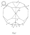
- the plugs shown in Figs. 1 and 2 consist essentially of refractory material of appropriate density to float at the steel slag interface. This may be for example a suitable type of refractory concrete.
- Fig. 1 shows an embodiment in which the plug has fourteen flat faces, of which six large faces 5 intersect each other at 90° and eight small triangular faces 6 form bevels at the corners. There are thus twenty four angles, each angle being the meeting point for three intersecting meeting lines of the faces. For example angle 1 is formed by the intersecting lines 2, 3 and 4.
- the plug may be lifted or tipped into a converter using an eye 7.
- Each of the faces 6 intersects each of the three adjacent larger faces 5 at an obtuse angle.
- the shape of the plug enables it to roll easily to lodge in the taphole of the steel converter.
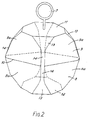
- Fig. 2 shows a further improved plug with edges bevelled off more.
- the shape of this plug reduces the risk of the angles crumbling away and improves its ability to roll.
- the plug is a body of polyhedral shape having a rectangular central plane of symmetry 10 and mutually symmetrical upper and lower halves 8, 9 on each side of this central plane.
- Each half 8, 9 has four large planar faces 8a, 9a meeting the central plane of symmetry 10 and extending away from it at an angle less than 90°, specifically 75° and a planar end face 11, 12 meeting all the first planar faces 8a, 9a and lying parallel to the central plane of symmetry 10.
- There are rounded surfaces 14 at meeting zones of each adjacent pair of the first planar faces 8a, 9a.
- Both the lower half 8 and the upper half 9 have a tapering shape. This has the advantage that the mould or die which is used for making the plug may be re-used. This reduces the production costs of the plug to a significant degree.
- the plugs illustrated are each 205 mm high and have maximum widths of 205 mm.
Landscapes
- Engineering & Computer Science (AREA)
- Chemical & Material Sciences (AREA)
- Manufacturing & Machinery (AREA)
- Materials Engineering (AREA)
- Metallurgy (AREA)
- Organic Chemistry (AREA)
- Mechanical Engineering (AREA)
- General Engineering & Computer Science (AREA)
- Carbon Steel Or Casting Steel Manufacturing (AREA)
Claims (7)
Applications Claiming Priority (2)
| Application Number | Priority Date | Filing Date | Title |
|---|---|---|---|
| NL8801231A NL8801231A (nl) | 1988-05-11 | 1988-05-11 | Stop voor een staalconverter. |
| NL8801231 | 1988-05-11 |
Publications (2)
| Publication Number | Publication Date |
|---|---|
| EP0341798A1 EP0341798A1 (de) | 1989-11-15 |
| EP0341798B1 true EP0341798B1 (de) | 1992-01-02 |
Family
ID=19852290
Family Applications (1)
| Application Number | Title | Priority Date | Filing Date |
|---|---|---|---|
| EP19890201175 Expired EP0341798B1 (de) | 1988-05-11 | 1989-05-09 | Abstichstopfen für einen Stahlkonverter, um das Mitlaufen von Abstichschlacke zu vermeiden |
Country Status (5)
| Country | Link |
|---|---|
| EP (1) | EP0341798B1 (de) |
| CA (1) | CA1315100C (de) |
| DE (1) | DE68900631D1 (de) |
| ES (1) | ES2029113T3 (de) |
| NL (1) | NL8801231A (de) |
Families Citing this family (1)
| Publication number | Priority date | Publication date | Assignee | Title |
|---|---|---|---|---|
| RU2148656C1 (ru) * | 1998-12-08 | 2000-05-10 | АО "Новолипецкий металлургический комбинат" | Стопор для отсечки шлака в конвертере |
Family Cites Families (2)
| Publication number | Priority date | Publication date | Assignee | Title |
|---|---|---|---|---|
| CA1218846A (en) * | 1982-05-10 | 1987-03-10 | James G. Bassett, Jr. | Method of minimizing slag carryover |
| DE8317252U1 (de) * | 1983-06-13 | 1983-11-24 | Thyssen Stahl AG, 4100 Duisburg | Verschlussorgan zum zurueckhalten der schlacke waehrend des abstiches aus einem konverter |
-
1988
- 1988-05-11 NL NL8801231A patent/NL8801231A/nl not_active Application Discontinuation
-
1989
- 1989-05-09 ES ES89201175T patent/ES2029113T3/es not_active Expired - Lifetime
- 1989-05-09 DE DE8989201175T patent/DE68900631D1/de not_active Expired - Lifetime
- 1989-05-09 EP EP19890201175 patent/EP0341798B1/de not_active Expired
- 1989-05-10 CA CA000599207A patent/CA1315100C/en not_active Expired - Fee Related
Also Published As
| Publication number | Publication date |
|---|---|
| DE68900631D1 (de) | 1992-02-13 |
| CA1315100C (en) | 1993-03-30 |
| ES2029113T3 (es) | 1992-07-16 |
| EP0341798A1 (de) | 1989-11-15 |
| NL8801231A (nl) | 1989-12-01 |
Similar Documents
| Publication | Publication Date | Title |
|---|---|---|
| EP0666088B1 (de) | Muster for Vertiefungen an einem Golfball | |
| EP0484612B1 (de) | Golfball | |
| NZ224897A (en) | Golf ball with three parting lines not intersecting dimples; symmetrical dimple pattern either side of lines | |
| CA2279771A1 (en) | Block assembly and wall constructed therefrom | |
| NZ224898A (en) | Golf ball with six parting lines not intersecting dimples; symmetrical dimple pattern either side of lines | |
| DE60220060T2 (de) | Wirbelbildung inhibitor mit opferkörper | |
| US4871148A (en) | Vortex inhibitor for molten metal discharge | |
| EP0341798B1 (de) | Abstichstopfen für einen Stahlkonverter, um das Mitlaufen von Abstichschlacke zu vermeiden | |
| EP2288734B1 (de) | Wirbelinhibitor | |
| FR2647435B1 (fr) | Refractaires d'oxyde chromique avec une meilleure resistance au choc thermique et procede pour leur fabrication | |
| DD218743A3 (de) | Wendeschneidplatte mit spanformenden und spanbrechenden ausnehmungen | |
| EP0094688B1 (de) | Verfahren zur Herstellung eines Stahlgussstückes | |
| USRE37417E1 (en) | Vortex inhibitor for molten metal discharge | |
| EP0229262A2 (de) | Spüle, insbesondere Küchenspüle, und Verfahren zum Herstellen eines Formteiles für diese Spüle | |
| US3302256A (en) | Gasifiable feeder head pattern | |
| GB2183704A (en) | Armour blocks for protecting water bordering structures | |
| CA1218846A (en) | Method of minimizing slag carryover | |
| KR100498096B1 (ko) | 상,하층 엇갈림 2층구조의 용강와류방지체 | |
| JPS63186670A (ja) | ゴルフボ−ル | |
| JPH0649420Y2 (ja) | スライデイングノズル用プレートれんが | |
| DE3433349A1 (de) | Vorrichtung zum einfuehren von gas in eine metallschmelze | |
| ZA8948B (en) | Metallic coolant for a metallurgical bath,method of manufacture thereof and a method of continuous casting | |
| US3558096A (en) | Groove forming additions for the inner walls of hot tops | |
| JP2918451B2 (ja) | バレル式電気メッキ法 | |
| JP2001294295A (ja) | 原料装入用ホッパ |
Legal Events
| Date | Code | Title | Description |
|---|---|---|---|
| PUAI | Public reference made under article 153(3) epc to a published international application that has entered the european phase |
Free format text: ORIGINAL CODE: 0009012 |
|
| 17P | Request for examination filed |
Effective date: 19890509 |
|
| AK | Designated contracting states |
Kind code of ref document: A1 Designated state(s): BE DE ES FR GB LU NL |
|
| 17Q | First examination report despatched |
Effective date: 19910326 |
|
| GRAA | (expected) grant |
Free format text: ORIGINAL CODE: 0009210 |
|
| AK | Designated contracting states |
Kind code of ref document: B1 Designated state(s): BE DE ES FR GB LU NL |
|
| ET | Fr: translation filed | ||
| REF | Corresponds to: |
Ref document number: 68900631 Country of ref document: DE Date of ref document: 19920213 |
|
| REG | Reference to a national code |
Ref country code: ES Ref legal event code: FG2A Ref document number: 2029113 Country of ref document: ES Kind code of ref document: T3 |
|
| PLBE | No opposition filed within time limit |
Free format text: ORIGINAL CODE: 0009261 |
|
| STAA | Information on the status of an ep patent application or granted ep patent |
Free format text: STATUS: NO OPPOSITION FILED WITHIN TIME LIMIT |
|
| 26N | No opposition filed | ||
| PGFP | Annual fee paid to national office [announced via postgrant information from national office to epo] |
Ref country code: FR Payment date: 19930408 Year of fee payment: 5 |
|
| PGFP | Annual fee paid to national office [announced via postgrant information from national office to epo] |
Ref country code: GB Payment date: 19930415 Year of fee payment: 5 |
|
| PGFP | Annual fee paid to national office [announced via postgrant information from national office to epo] |
Ref country code: DE Payment date: 19930421 Year of fee payment: 5 |
|
| PGFP | Annual fee paid to national office [announced via postgrant information from national office to epo] |
Ref country code: BE Payment date: 19930427 Year of fee payment: 5 |
|
| PGFP | Annual fee paid to national office [announced via postgrant information from national office to epo] |
Ref country code: ES Payment date: 19930428 Year of fee payment: 5 |
|
| PGFP | Annual fee paid to national office [announced via postgrant information from national office to epo] |
Ref country code: LU Payment date: 19930503 Year of fee payment: 5 |
|
| PGFP | Annual fee paid to national office [announced via postgrant information from national office to epo] |
Ref country code: NL Payment date: 19930531 Year of fee payment: 5 |
|
| EPTA | Lu: last paid annual fee | ||
| PG25 | Lapsed in a contracting state [announced via postgrant information from national office to epo] |
Ref country code: LU Free format text: LAPSE BECAUSE OF NON-PAYMENT OF DUE FEES Effective date: 19940509 Ref country code: GB Effective date: 19940509 |
|
| PG25 | Lapsed in a contracting state [announced via postgrant information from national office to epo] |
Ref country code: ES Free format text: LAPSE BECAUSE OF NON-PAYMENT OF DUE FEES Effective date: 19940510 |
|
| PG25 | Lapsed in a contracting state [announced via postgrant information from national office to epo] |
Ref country code: BE Effective date: 19940531 |
|
| BERE | Be: lapsed |
Owner name: HOOGOVENS GROEP B.V. Effective date: 19940531 |
|
| PG25 | Lapsed in a contracting state [announced via postgrant information from national office to epo] |
Ref country code: NL Effective date: 19941201 |
|
| GBPC | Gb: european patent ceased through non-payment of renewal fee |
Effective date: 19940509 |
|
| NLV4 | Nl: lapsed or anulled due to non-payment of the annual fee | ||
| PG25 | Lapsed in a contracting state [announced via postgrant information from national office to epo] |
Ref country code: FR Effective date: 19950131 |
|
| PG25 | Lapsed in a contracting state [announced via postgrant information from national office to epo] |
Ref country code: DE Effective date: 19950201 |
|
| REG | Reference to a national code |
Ref country code: FR Ref legal event code: ST |
|
| REG | Reference to a national code |
Ref country code: ES Ref legal event code: FD2A Effective date: 19990405 |