EP0341784A2 - Flüssigkeitschromatographie - Google Patents
Flüssigkeitschromatographie Download PDFInfo
- Publication number
- EP0341784A2 EP0341784A2 EP19890201153 EP89201153A EP0341784A2 EP 0341784 A2 EP0341784 A2 EP 0341784A2 EP 19890201153 EP19890201153 EP 19890201153 EP 89201153 A EP89201153 A EP 89201153A EP 0341784 A2 EP0341784 A2 EP 0341784A2
- Authority
- EP
- European Patent Office
- Prior art keywords
- pump
- piston
- seal
- liquid
- annular
- Prior art date
- Legal status (The legal status is an assumption and is not a legal conclusion. Google has not performed a legal analysis and makes no representation as to the accuracy of the status listed.)
- Withdrawn
Links
Images

Classifications
-
- G—PHYSICS
- G01—MEASURING; TESTING
- G01N—INVESTIGATING OR ANALYSING MATERIALS BY DETERMINING THEIR CHEMICAL OR PHYSICAL PROPERTIES
- G01N30/00—Investigating or analysing materials by separation into components using adsorption, absorption or similar phenomena or using ion-exchange, e.g. chromatography or field flow fractionation
- G01N30/02—Column chromatography
- G01N30/26—Conditioning of the fluid carrier; Flow patterns
- G01N30/28—Control of physical parameters of the fluid carrier
- G01N30/32—Control of physical parameters of the fluid carrier of pressure or speed
- G01N2030/326—Control of physical parameters of the fluid carrier of pressure or speed pumps
Definitions
- the invention relates to a liquid chromatography pump comprising a reciprocating piston in a cylinder and to a liquid chromatograph including such a pump.
- Such liquid chromatography pumps may be single or multiple piston pumps and are used to pump carrier liquids (solvents, buffers, etc.) through a chromatographic column at high pressures, typically up to 400 bar.
- the pistons which have to be inert to the various solvents used, are typically of saphire, stainless steel, or titanium and pass thorough annular seals which, for example, may be made from PTFE or polythene.
- Providing an effective seal for liquid chromatography pumps employing reciprocating pistons which have a long life with the various solvents and buffers used has proved difficult. Liquid clinging to the surface of the pistons passes through the seals and in some circumstances can evaporate and leave a crystaline deposit on the surface of the pistons.
- the invention provides a liquid chromatography pump comprising a cylinder containing a reciprocating piston having a delivery stroke and a suction stroke, a first annular piston seal, and a second annular piston seal arranged adjacent to the first annular piston seal and located and dimensioned such that the portion of the piston which passes through the first annular seal on the suction stroke of the piston does not extend beyond the second annular seal so that liquid carried through the first annular seal on the surface of the piston is not exposed to the atmosphere.
- a second piston seal in such a position as to prevent the portion of the surface of the piston on which the liquid is deposited from coming into free contact with the atmosphere reduces the evaporation of the liquid and minimises the formation of crystals which might damage the seals.
- the provision of a second seal is mechanically simple and does not entail a large cost or a larger pump.
- the pump may be a multiple piston pump, first and second seals being provided for each piston. Multiple piston pumps enable a more even flow rate to be achieved which is desirable in liquid chromatographs.
- the invention further provides a liquid chromatograph comprising a pump, a sample injector, a separating column, and a detector wherein the pump is substantially as set forth herein.
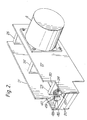
- the liquid chromatograph shown in Figure 1 comprises a pump 1 for pumping liquid through a separating column 2.
- the pump 1 is coupled by a shaft 3 to a stepper motor 4 which drives the pump 1.
- a pressure transducer 5 is provided to monitor the pressure at the outlet of the pump 1.
- a sample injector 6 is connected between the outlet of the pump 1 and the inlet to the column 2.
- the outlet of the column 2 is connected to a detector 7 which produces an electrical output which is fed to signal processing circuitry 8.
- the output of the signal processing circuitry 8 drives a display device 9 which may take any convenient form, for example a chart recorder or a video display unit.
- the stepper motor 4 is driven by a stepper motor drive unit 10 which feeds stepping pulses at a desired rate to the motor 4 over a path 11.
- the stepper motor drive circuit 10 receives a first input from an input unit 12 over a path 13.
- the input unit 12 may be a keyboard to allow the desired flow rate to be entered by an operator or may be any other arrangement which allows the operating parameters of the chromatograph to be set up.
- the stepper motor drive circuit also receives a second input over a path 14 from the pressure transducer 5.
- the inlet of the pump 1 is fed from a solvent mixing arrangement 15 which is controlled by signals from the input unit 12 over a path 16.
- a desired flow rate is set up using the input unit 12 which produces signals which enable the stepper motor drive circuit 10 to produce stepping pulses to drive the stepper motor 4 at the appropriate speed to produce the desired flow rate.
- the flow rate will not remain constant unless measures are taken to make it so.
- One possibility is to insert a pulse damper between the outlet of the pump and the inlet of the column but this increases the liquid filled volume of the system and slows the change in proportions of solvents.
- With a single piston pump it is usual to make the suction portion of the pump cycle as small as possible either by design of the cam profile or by increasing the speed of the stepper motor during the suction stroke. The increase in the speed may be in response to the measured outlet pressure of the pump as monitored by the transducer 5.
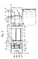
- the pump shown in Figures 2 and 3 is similar to that shown in UK Patent Applications Nos. 2180467 (PHB33205) and 2195473 (PHB33295) and may be controlled as described in those patent applications.
- the pump 1 comprises a pump head 20 which is clamped between two side panels 21 and 22 made from sheet steel.
- the pump assembly has cross pieces 23, 24 and 25 to provide a rigid structure onto which the motor 4 and various component parts of the pump are mounted.
- the pump 1 is provided with two pistons 26, 27 mounted in respective rods 28, 29 which pass into the interior of two tubes 30, 31.
- the tube 30 is slidably mounted in bearings 32, 33 in cross pieces 23 and 24 while the tube 31 is similarly mounted in bearings 34 and 35.
- Two cams 36 and 37 are mounted on the shaft 3 of the motor 4 and the tubes 30 and 31 are provided with respective cam followers 38 and 39.
- Coil springs 40 and 41 bias the cam followers 38 and 39 against the cams 36 and 37 by way of projections (not shown) on the rods 28 and 29, the rods 28 and 29 bearing against transverse members in the tubes 30 and 31.
- a transverse portion 42 of an L shaped bracket 43 provides a bearing surface for the other ends of the springs 40 and 41.
- Two circlips 44 and 45 are provided on the rods 28 and 29 to retain the pistons 26, 27 in the head 20 when the head is dismantled from the rest of the pump assembly.
- Two tubes 46, 47 take the outlets from each cylinder of the pump head 20 and combine them in a manifold 48 having an outlet 49 which forms the pump outlet.
- a shaft encoder 50 is attached to the shaft 3 of the motor 4 and a detector 51, which may be an opto electronic detector, is carried by a bracket 52 attached to the side panel 21 of the pump.
- the motor 4 is supplied with stepping pulses by the drive circuit 10 ( Figure 1) and causes the shaft 3 to rotate at a desired speed. Consequently the cams 36 and 37 cause the pistons 26 and 27 to advance and retract in accordance with the cam profiles which are designed to cause the pistons to advance on their delivery strokes at a constant linear velocity when the cams have a constant angular velocity.
- the design of such a cam profile is well known to those skilled in the art.
- the pistons are arranged to have overlapping delivery strokes, i.e. there is a period of time during each revolution of the motor when both pistons are advancing.
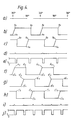
- Figure 4 illustrates the delivery of liquid by each piston and the motor speed at various points during a pumping cycle.
- Figure 4a shows the cam angles.
- Figure 4b shows the delivery cycle of piston 26 and shows that at point Ax the delivery stroke begins, i.e. the piston starts to advance, but that precompression of the liquid is occurring and no actual delivery of liquid takes place until point Ay. From point Ay until point Az delivery of liquid at a constant rate takes place since the piston is advancing at a constant linear velocity, point Az being the point at which the piston reaches top dead centre and thus liquid can no longer be delivered.
- Figure 4c shows the delivery cycle of piston 27, the points Bx, By and Bz corresponding to the same points on the delivery cycle of piston 27 as points Ax, Ay and Az of piston 26.
- Figure 4 f) to j) illustrates in a similar way to Figure 4b) to e) the situation where three pistons are provided in the pump and the cam profiles are such that at any one time either one or two of the pistons is/are delivering liquid.
- the advantage provided by the use of three pistons operating as illustrated in Figure 4 is that a longer period is available for filling each cylinder with the solvent which is to be pumped, i.e. the period A′z to A′x is longer than the period Az to Ax. This may be of importance when several liquids are being serially fed into each cylinder to give a desired solvent mix for pumping, particularly at high flow rates when the fill time becomes shorter since the total pump cycle time becomes shorter. Thus it becomes advantageous to make the fill time as large proportion of the pump cycle time. Of course more than three pistons could be used giving even longer fill times but every added piston increases the mechanical complexity and hence cost.
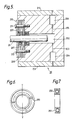
- FIG. 5 shows a cross-sectional view of the pump head 20 taken on line x-x of Figure 3.
- the pump head 20 comprises a block 201 in which a cylinder 202 is formed.
- the cylinder 202 communicates with an inlet tube 203 which leads from an inlet check valve 204 and an outlet tube 205 which leads from an outlet check valve 206.
- the piston 26 reciprocates in the cylinder 202 and has a first annular seal 207 which may be formed, for example, from PTFE or high density polythene depending on the solvents or buffers with which the pump is intended to be used.
- a first backing plate 208 is provided to locate the seal 207.
- a second seal 209 of the same form as the first seal 207 is provided on the piston 26 and located in a recess in the backing plate 208.
- a second backing plate 210 is provided to retain the second seal 209 on the piston 26.
- the backing plates 208 and 210 are retained by two bolts 211 and 212 which pass through the backing plates into the block 201.
- Two further plates 213 and 214 retain the inlet and outlet check valves 204 and 206 in the block 201.
- the seal 207 is shown on an enlarged scale in Figures 6 and 7 and is annular in form, the annulus being of the form of a U-shaped channel 250 in which a coil spring 251 is located.
- the spring 251 biases the arms of the 'U' apart.
- the seal 207 is located with the open end of the 'U' facing the cylinder so that as the liquid in the cylinder is pressurised it tends to force the arms of the 'U' apart which increases the effectiveness of the seal as the pressure increases.
- the seal 209 need not be of the same construction as the seal 207 but if, as shown in Figure 5, it is of the same form, it should preferably be arranged back-to-back with the seal 209 otherwise liquid will gather in the U-shaped channel of the second seal and carry-over from one solvent to another will occur.
- seals 207 and 209 are so dimensioned that the distance between their outer ends is greater than the stroke of the piston, the part of the surface of the piston to which the liquid clings when passing through the seal 207 does not become exposed to the atmosphere beyond the seal 209. In this way evaporation or crystalization of liquid solvents or buffers is substantially reduced leading to s significantly increased effectiveness and life of the seals. Further the life of the pistons may be increased due to the reduced likelihood of scoring by crystals or other contaminants. However, an improved performance may be obtained even if that separation is not provided.
- liquid chromatography reciprocating pumps having any number of pistons and controlled by any method or apparatus.
- the liquid chromatograph pump described is merely one example of such a pump to which the invention can be applied.
Landscapes
- General Health & Medical Sciences (AREA)
- Health & Medical Sciences (AREA)
- Life Sciences & Earth Sciences (AREA)
- Chemical & Material Sciences (AREA)
- Analytical Chemistry (AREA)
- Biochemistry (AREA)
- Physics & Mathematics (AREA)
- General Physics & Mathematics (AREA)
- Immunology (AREA)
- Pathology (AREA)
- Details Of Reciprocating Pumps (AREA)
- Reciprocating Pumps (AREA)
- Treatment Of Liquids With Adsorbents In General (AREA)
Applications Claiming Priority (2)
| Application Number | Priority Date | Filing Date | Title |
|---|---|---|---|
| GB8811446 | 1988-05-13 | ||
| GB8811446A GB2218474A (en) | 1988-05-13 | 1988-05-13 | Liquid chromatography |
Publications (2)
| Publication Number | Publication Date |
|---|---|
| EP0341784A2 true EP0341784A2 (de) | 1989-11-15 |
| EP0341784A3 EP0341784A3 (de) | 1991-04-10 |
Family
ID=10636907
Family Applications (1)
| Application Number | Title | Priority Date | Filing Date |
|---|---|---|---|
| EP19890201153 Withdrawn EP0341784A3 (de) | 1988-05-13 | 1989-05-05 | Flüssigkeitschromatographie |
Country Status (4)
| Country | Link |
|---|---|
| EP (1) | EP0341784A3 (de) |
| JP (1) | JPH0211868A (de) |
| AU (1) | AU3471789A (de) |
| GB (1) | GB2218474A (de) |
Cited By (1)
| Publication number | Priority date | Publication date | Assignee | Title |
|---|---|---|---|---|
| EP0855507A3 (de) * | 1997-01-23 | 1999-11-03 | Sarcos, Inc. | Volumetrische Pumpe mit eine Zweirichtungsdichtung |
Families Citing this family (1)
| Publication number | Priority date | Publication date | Assignee | Title |
|---|---|---|---|---|
| US6918595B2 (en) * | 2002-11-22 | 2005-07-19 | Dionex Corporation | Seal for high-pressure pumping system |
Family Cites Families (10)
| Publication number | Priority date | Publication date | Assignee | Title |
|---|---|---|---|---|
| FR1224096A (fr) * | 1958-01-24 | 1960-06-22 | Perfectionnements aux dispositifs à pression de fluide, et plus spécialement aux pompes | |
| ES305323A1 (es) * | 1964-10-16 | 1965-02-01 | Ciedad Anenima Com Espanola Pa | Cilindro de accionamiento neumatico alternativo |
| DE2109502B2 (de) * | 1971-03-01 | 1972-08-17 | Burmeister & Wains Mot Mask | Dichtungsanordnung fuer einen spalt zwischen zwei koaxialen hin- und hergehenden zylindrischen elementen |
| US3922957A (en) * | 1974-04-08 | 1975-12-02 | Beckman Instruments Inc | Microflow metering pump |
| US4013386A (en) * | 1975-09-08 | 1977-03-22 | Hardman Incorporated | Positive displacement metering pump |
| JPS53139204A (en) * | 1977-05-12 | 1978-12-05 | Shikutani Kk | Horizontal type plunger pump |
| US4242062A (en) * | 1979-08-06 | 1980-12-30 | Lear Siegler, Inc. | Dual piston pump with pressure seal lubrication feature |
| SE449508B (sv) * | 1982-03-09 | 1987-05-04 | Lkb Produkter Ab | Anordning vid en kolvpump for pumpning av ett pumpmedium |
| DE3616476A1 (de) * | 1985-05-20 | 1986-11-20 | Graco Inc., Minneapolis, Minn. | Fluessigkeitspumpe |
| GB2180467A (en) * | 1985-09-18 | 1987-04-01 | Philips Electronic Associated | Liquid chromatograph |
-
1988
- 1988-05-13 GB GB8811446A patent/GB2218474A/en not_active Withdrawn
-
1989
- 1989-05-05 EP EP19890201153 patent/EP0341784A3/de not_active Withdrawn
- 1989-05-11 JP JP1116207A patent/JPH0211868A/ja active Pending
- 1989-05-12 AU AU34717/89A patent/AU3471789A/en not_active Abandoned
Cited By (1)
| Publication number | Priority date | Publication date | Assignee | Title |
|---|---|---|---|---|
| EP0855507A3 (de) * | 1997-01-23 | 1999-11-03 | Sarcos, Inc. | Volumetrische Pumpe mit eine Zweirichtungsdichtung |
Also Published As
| Publication number | Publication date |
|---|---|
| AU3471789A (en) | 1989-11-16 |
| GB2218474A (en) | 1989-11-15 |
| JPH0211868A (ja) | 1990-01-16 |
| GB8811446D0 (en) | 1988-06-15 |
| EP0341784A3 (de) | 1991-04-10 |
Similar Documents
| Publication | Publication Date | Title |
|---|---|---|
| US4752385A (en) | Liquid chromatograph | |
| US4003679A (en) | High pressure pump with metering | |
| EP0309596B1 (de) | Pumpvorrichtung zur Abgabe von Flüssigkeit bei hohem Druck | |
| US5253981A (en) | Multichannel pump apparatus with microflow rate capability | |
| US4552513A (en) | Multiple piston pump control | |
| US5755561A (en) | Piston pumping system delivering fluids with a substantially constant flow rate | |
| US5257914A (en) | Electronic control interface for fluid powered diaphragm pump | |
| US4919595A (en) | Fluid delivery system with deficit flow compensation | |
| US3985019A (en) | Liquid chromatography system with solvent proportioning | |
| CA1077739A (en) | High pressure liquid chromatography system | |
| US3847507A (en) | Liquid supply system by pump | |
| EP0303220A2 (de) | Verdrängerpumpe mit geringer Druckschwankung | |
| DE3874883T2 (de) | Fluessigkeitsfoerdernde kolbenpumpe. | |
| EP0757587A1 (de) | Mischvorrichtung zum pumpen von mikrodurchflussgradienten | |
| US4127360A (en) | Bumpless pump apparatus adjustable to meet slave system needs | |
| US3572130A (en) | Liquid sample pick-up and dispensing apparatus | |
| EP0278739A1 (de) | Saugpumpe mit konstanter Förderleistung für die Hochleistungs-Flüssigkeitschromatographie | |
| EP0341784A2 (de) | Flüssigkeitschromatographie | |
| US7048512B2 (en) | Method and system intended for fine proportioning of fluids injected into a pumping installation with check valve proportioning compensation | |
| GB1505521A (en) | Liquid chromatography apparatus and method | |
| US5869774A (en) | Device for taking a liquid sample | |
| JPS61178582A (ja) | 送液ポンプ装置 | |
| SU507205A3 (ru) | Устройство дл капельного вливани | |
| US4734187A (en) | Constant suction gradient pump for high performance liquid chromatography | |
| US4930991A (en) | Piston pump for high performance liquid chromatography |
Legal Events
| Date | Code | Title | Description |
|---|---|---|---|
| PUAI | Public reference made under article 153(3) epc to a published international application that has entered the european phase |
Free format text: ORIGINAL CODE: 0009012 |
|
| AK | Designated contracting states |
Kind code of ref document: A2 Designated state(s): CH DE ES FR GB IT LI NL SE |
|
| PUAL | Search report despatched |
Free format text: ORIGINAL CODE: 0009013 |
|
| AK | Designated contracting states |
Kind code of ref document: A3 Designated state(s): CH DE ES FR GB IT LI NL SE |
|
| RHK1 | Main classification (correction) |
Ipc: F04B 21/08 |
|
| RAP3 | Party data changed (applicant data changed or rights of an application transferred) |
Owner name: N.V. PHILIPS' GLOEILAMPENFABRIEKEN Owner name: PHILIPS ELECTRONICS UK LIMITED |
|
| STAA | Information on the status of an ep patent application or granted ep patent |
Free format text: STATUS: THE APPLICATION IS DEEMED TO BE WITHDRAWN |
|
| 18D | Application deemed to be withdrawn |
Effective date: 19911011 |