EP0341600A2 - Cutting device of web for packing - Google Patents
Cutting device of web for packing Download PDFInfo
- Publication number
- EP0341600A2 EP0341600A2 EP89108133A EP89108133A EP0341600A2 EP 0341600 A2 EP0341600 A2 EP 0341600A2 EP 89108133 A EP89108133 A EP 89108133A EP 89108133 A EP89108133 A EP 89108133A EP 0341600 A2 EP0341600 A2 EP 0341600A2
- Authority
- EP
- European Patent Office
- Prior art keywords
- web
- blade
- cylindrical body
- suction
- packing
- Prior art date
- Legal status (The legal status is an assumption and is not a legal conclusion. Google has not performed a legal analysis and makes no representation as to the accuracy of the status listed.)
- Granted
Links
Images


Classifications
-
- B—PERFORMING OPERATIONS; TRANSPORTING
- B65—CONVEYING; PACKING; STORING; HANDLING THIN OR FILAMENTARY MATERIAL
- B65H—HANDLING THIN OR FILAMENTARY MATERIAL, e.g. SHEETS, WEBS, CABLES
- B65H35/00—Delivering articles from cutting or line-perforating machines; Article or web delivery apparatus incorporating cutting or line-perforating devices, e.g. adhesive tape dispensers
-
- B—PERFORMING OPERATIONS; TRANSPORTING
- B26—HAND CUTTING TOOLS; CUTTING; SEVERING
- B26D—CUTTING; DETAILS COMMON TO MACHINES FOR PERFORATING, PUNCHING, CUTTING-OUT, STAMPING-OUT OR SEVERING
- B26D7/00—Details of apparatus for cutting, cutting-out, stamping-out, punching, perforating, or severing by means other than cutting
- B26D7/01—Means for holding or positioning work
- B26D7/015—Means for holding or positioning work for sheet material or piles of sheets
-
- B—PERFORMING OPERATIONS; TRANSPORTING
- B26—HAND CUTTING TOOLS; CUTTING; SEVERING
- B26D—CUTTING; DETAILS COMMON TO MACHINES FOR PERFORATING, PUNCHING, CUTTING-OUT, STAMPING-OUT OR SEVERING
- B26D7/00—Details of apparatus for cutting, cutting-out, stamping-out, punching, perforating, or severing by means other than cutting
- B26D7/18—Means for removing cut-out material or waste
- B26D7/1845—Means for removing cut-out material or waste by non mechanical means
- B26D7/1863—Means for removing cut-out material or waste by non mechanical means by suction
-
- Y—GENERAL TAGGING OF NEW TECHNOLOGICAL DEVELOPMENTS; GENERAL TAGGING OF CROSS-SECTIONAL TECHNOLOGIES SPANNING OVER SEVERAL SECTIONS OF THE IPC; TECHNICAL SUBJECTS COVERED BY FORMER USPC CROSS-REFERENCE ART COLLECTIONS [XRACs] AND DIGESTS
- Y10—TECHNICAL SUBJECTS COVERED BY FORMER USPC
- Y10T—TECHNICAL SUBJECTS COVERED BY FORMER US CLASSIFICATION
- Y10T83/00—Cutting
- Y10T83/04—Processes
- Y10T83/0596—Cutting wall of hollow work
-
- Y—GENERAL TAGGING OF NEW TECHNOLOGICAL DEVELOPMENTS; GENERAL TAGGING OF CROSS-SECTIONAL TECHNOLOGIES SPANNING OVER SEVERAL SECTIONS OF THE IPC; TECHNICAL SUBJECTS COVERED BY FORMER USPC CROSS-REFERENCE ART COLLECTIONS [XRACs] AND DIGESTS
- Y10—TECHNICAL SUBJECTS COVERED BY FORMER USPC
- Y10T—TECHNICAL SUBJECTS COVERED BY FORMER US CLASSIFICATION
- Y10T83/00—Cutting
- Y10T83/202—With product handling means
- Y10T83/2066—By fluid current
- Y10T83/207—By suction means
-
- Y—GENERAL TAGGING OF NEW TECHNOLOGICAL DEVELOPMENTS; GENERAL TAGGING OF CROSS-SECTIONAL TECHNOLOGIES SPANNING OVER SEVERAL SECTIONS OF THE IPC; TECHNICAL SUBJECTS COVERED BY FORMER USPC CROSS-REFERENCE ART COLLECTIONS [XRACs] AND DIGESTS
- Y10—TECHNICAL SUBJECTS COVERED BY FORMER USPC
- Y10T—TECHNICAL SUBJECTS COVERED BY FORMER US CLASSIFICATION
- Y10T83/00—Cutting
- Y10T83/465—Cutting motion of tool has component in direction of moving work
- Y10T83/4749—Tool mounted on oscillating standard
- Y10T83/4751—Both tools of couple on single standard
Definitions
- the present invention generally relates to cutting devices of web for packing.
- this web is cut into an independent cylindrical body.
- the dust such as paper powder is not removed which may possibly be generated when the web is cut with the upper blade and the lower blade.
- the web is cut by the upper blade and the lower blade which are maintained in perfect state.
- paper dust is generated. There was no guarantee that such paper dust attached to a part, such as the inner surface of the cut cylindrical body, to be mixed into the content of the packing.
- the main object of the present invention is to provide a cutting device of web for packing in which when the web for packing is cut, dust such as paper powder is removed by sucking the air around the cut portion of the cut cylindrical body so that dust attached or possibly attached to the cylindrical body can be removed.
- a cutting device which is used to cut a web of cylindrical shape into an independent cylindrical body, comprising a suction port which is provided on the side of the blade body of the upper blade or the lower blade which opposes to the sectional face of the cut cylindrical body.
- This suction port is connected to a suction device such as a blower so as to suck in the air around the cut portion of the cylindrical body.
- the cutting device of the invention has effective means by which at least a part of the suction port is disposed at a position directly opposing the space in the cylinder which is formed by the elasticity of the cut cylindrical body itself or the air sucked in from the suction port is discharged to the atmosphere via a dust collector.
- the blade body frame where the upper blade and lower blade are disposed is supported by means of a shaft so as to make the blade body frame oscillatable.
- the suction duct to be connected to the blower is fixed to the front of the blade body frame and the suction port and the suction duct is connected by a flexible tube.
- the cut cylinder body When the web is cut by the cutting action of the upper blade and the lower blade of the cutting device according to the invention, the cut cylinder body is positioned in front of the upper blade or the lower blade. At this time, if the air around the cut portion is sucked from the suction port provided on the side of the blade body, paper powder and other dust generated during cutting will be sucked in and removed.
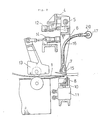
- FIG. 1 relates to a web, 1′ to a cylindrical body, 5 to a shaft, 6 to a blade body frame, 7 to an upper blade, 8 to a lower blade, 9 to a guide lever, 10 to a lower blade supporting block, 11 to a cylinder, 15 to a suction port, 16 to a flexible tube, 17 to a suction duct, 18 to a blower, 19 to a dust collector, 20 to an elbow and 21 to a cylindrical space.
- Fig. 7 shows an embodiment of a web for packing, wherein the flat band-like web 1 is turned up from both sides, the edges thereof are joined and formed into a cylindrical shape.
- the web 1 which is formed into continuous cylindrical shape is cut at a specific position to get an independent cylindrical body 1′ which is used for forming a container for packing.
- This web 1 is drawn with the line for bending shown by alternate long and two short dashes line and a notch 3 is provided at the specific cutting position.
- the web 1 ist turned up from both sides thereof and formed to a cylindrical shape, the cylinder expands to some extent by the elasticity of the web itself and the dimension between the lines for bending on both sides and the dimension of the flat part to be turned up and joined are different so as to facilitate subsequent work.
- the upper and lower blade bodies which form the cutting device for the web are supported by a shaft 5 with respect to the body frame 4 and mounted on the blade body frame 6 which is oscillatable in the advancing direction of the web 1.
- the upper blade 7 and the lower blade 8 which is associated to the upper blade 7 and is fixed to a lower blade supporting block 10 which is made slidable in vertical direction at the position concerned.
- the lower blade supporting block 10 by vertically moving and driving the lower blade supporting block 10 it is obtained that the web 1 is cut.
- the blade body frame 6 is osciallated into the advancing direction of the web 1 by a separate cylinder 12.
- the notch 3 of the web 1 and the upper blade 7 are caused to engage when moving the blade body frame 6 toward the front of the web advancing direction, so that the cylinder 11 is driven under such condition to cut the web 1 at the specified position as shown in Fig. 2 and Fig. 4.
- FIG. 3 On the side of the blade body of the upper blade 7 are opened two oblong suction ports 15, 15 at a position opposing to the cutting face of the cut cylindrical body 1′.
- These suction ports 15, 15 are connected to the suction duct 17 which is fixed at the front of the oscillating frame 6 by means of flexible tubes 16, 16 respectively.
- One end of the suction duct 17 is connected to the blower 18 which performs sucking action so as to suck the air from around the suction port 15.
- the air is passed through the bag filter type dust collector 19 so that dust such as paper powder which is sucked in together with the air is removed.
- this dust collector 19 may be of other type such as an electric dust collector or an inertia dust collector.
- an elbow 20 is provided which is opened in the suction duct 17 in the direction of air flow.
- One end of this elbow 20 is caused to open outside of the tube through the tube wall of the suction duct.
- the other end of the flexible tube 16 whose one end is connected to the suction port is connected to this elbow 20.
- suction port 15 which is caused to open on the side of the blade body of the upper blade or the lower blade, if the cutting face of the cylindrical body 1′ is in a zone where dust is sucked in by suction (hereafter called the suction area), the number and position of such suction port are not limited.
- two suction ports 15, 15 which are opposed to both ends of the cutting face of the cylindrical body 1′ are provided, so that the suction areas A, A expand all over the cutting face of the cylindrical body 1′.
- another suction port 15′ is additionally provided on the intermediate portion of the suction ports 15, so that the entire sectional face of the cylindrical body 1′ is covered by the suction areas A, A and A′ of these suction ports.
- a part or the whole of the suction ports 15, 15 and 15′ is provided at a position opposing the direction to the space 21 in the cylinder which is formed by the elasticity of the cut cylindrical body 1′ itself.
- the position of the suction port may be deviated either to above or below the cylindrical body 1′ if the suction area of the suction port expands all over the sectional face of the cylindrical body 1′.
- the suction port 15 is not opposed directly to the space 21 of the cylinder of the cylindrical body 1′, there is a possibility that the air flow in the space 21 in the cylinder is disturbed and the dust preventive effect by suction becomes insufficient.
- the cylindrical body 1′ itself acts like a tunnel and thus the air to be sucked does not cause turbulent flow inside the cylindrical body 1′ but flows as much in quantity as possible. Therefore, the removal and purificating action not only of the paper powder of the opposing sectional face but also the removal and purification action of the entire internal surface of the cylindrical body 1 are excellent.
Landscapes
- Life Sciences & Earth Sciences (AREA)
- Forests & Forestry (AREA)
- Engineering & Computer Science (AREA)
- Mechanical Engineering (AREA)
- Details Of Cutting Devices (AREA)
- Auxiliary Devices For And Details Of Packaging Control (AREA)
- Control And Other Processes For Unpacking Of Materials (AREA)
- Making Paper Articles (AREA)
- Cleaning In General (AREA)
- Surgical Instruments (AREA)
Abstract
Description
- The present invention generally relates to cutting devices of web for packing.
- It has been a general practice to pack beverage such as milk, juice, and yogurt with laminated materials which mainly use paper as base material and include synthetic resin material or metallic foils according to purposes. In packing means which employ such laminated materials, both edges of continuous belt shaped laminated materials (hereinafter called web) are joined into a cylindrical shape as shown in figure 7. The cylindrical shape is cut into an independent cylindrical body of specified dimensions and formed to a packing body of beverage by means of sealing means and filling means.
- In a cutting device used for cutting the web, which is formed into a cylindrical shape, this web is cut into an independent cylindrical body.
- In a cutting device of web which is formed into a cylindrical shape, usually the web of certain dimensions is sent out intermittently so that the web is cut by a cutting device comprising upper blade and lower blade. In order to perform accuate feeding of web, as disclosed in Japanese Laid-Open Patent No. 59-118658 (1984), there has been a concept known according to which a notch is provided on a part of the web and upper and lower blade bodies are made freely oscillatable in the advancing direction of the web to cause the notch of the web to engage with the upper blade thereby accurately controlling the cutting position.
- However, in a conventional cutting device, the dust such as paper powder is not removed which may possibly be generated when the web is cut with the upper blade and the lower blade. Hereby it is a premise that the web is cut by the upper blade and the lower blade which are maintained in perfect state. However, in case where the web made of paper as the base material, there is a possibility that paper dust is generated. There was no guarantee that such paper dust attached to a part, such as the inner surface of the cut cylindrical body, to be mixed into the content of the packing.
- Thus there is a demand for a cutting device of web for packing capable of removing fine dust such as paper powder which may possibly be generated during web cutting.
- In respect of a packing of beverage, the hygienic problem that foreign matters do not mix into the content of the packing is most important.
- The main object of the present invention is to provide a cutting device of web for packing in which when the web for packing is cut, dust such as paper powder is removed by sucking the air around the cut portion of the cut cylindrical body so that dust attached or possibly attached to the cylindrical body can be removed.
- According to the present invention there is provided a cutting device which is used to cut a web of cylindrical shape into an independent cylindrical body, comprising a suction port which is provided on the side of the blade body of the upper blade or the lower blade which opposes to the sectional face of the cut cylindrical body. This suction port is connected to a suction device such as a blower so as to suck in the air around the cut portion of the cylindrical body.
- So the cutting device of the invention has effective means by which at least a part of the suction port is disposed at a position directly opposing the space in the cylinder which is formed by the elasticity of the cut cylindrical body itself or the air sucked in from the suction port is discharged to the atmosphere via a dust collector.
- Further, the blade body frame where the upper blade and lower blade are disposed is supported by means of a shaft so as to make the blade body frame oscillatable. By this embodiment it is possible to utilize the oscillation of the blade body frame for positioning the accurate cutting position of the web. In a cutting device of web of the kind referred to above, the suction duct to be connected to the blower is fixed to the front of the blade body frame and the suction port and the suction duct is connected by a flexible tube.
- When the web is cut by the cutting action of the upper blade and the lower blade of the cutting device according to the invention, the cut cylinder body is positioned in front of the upper blade or the lower blade. At this time, if the air around the cut portion is sucked from the suction port provided on the side of the blade body, paper powder and other dust generated during cutting will be sucked in and removed.
- In a cutting device of web, in which at least a part of the suction port is directly opposed to the space in the cylinder which is formed by the elasticity of the cut cylindrical body itself, the air passing through the space in the cylinder is sucked into the suction port. Consequently, not only the dust around the cutting face but also the dust that has entered inside the cylinder will be sucked into the suction port.
- According to the cutting device of web for packing as described above, paper powder etc. which is possibly generated by the cutting action of the web can be removed and the possibility for even fine dust to mix inside the packing body of beverage can be reduced.
- By the preferred embodiment of the invention according to
claim 2, it is obtained that the air to be sucked passes through inside the cylindrical body thereby enhancing the dust preventive effect inside the cylindrical body. - In the preferred embodiment according to
claim 3, there is no possibility for the sucked dust to be discharged into the air, that is, the contamination of the working environment is prevented and the dust does not attach to the web. - In the preferred embodiment according to
claim 4, free movement of the blade body for cutting the web can be allowed. - Preferred embodiments of the cutting device of web for packing according to the present invention will hereinafter be described with reference to the accompanying drawings:
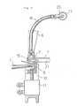
- Fig. 1 is a front view of a partial notch of the whole of the cutting device;
- Fig. 2 is a longitudinal side view of Fig. 1;
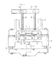
- Fig. 3 is an enlarged front view of the cutting blade portion showing the web after cutting;
- Fig. 4 is a longitudinal side view of Fig. 3;
- Fig. 5 and Fig. 6 are schematic front views showing the positional relationship between the cut cylindrical body and the suction ports provided on the side of the blade body; and
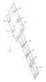
- Fig. 7 is a perspective view showing an example of the processing procedures of the web for packing.
- In the
drawings 1 relates to a web, 1′ to a cylindrical body, 5 to a shaft, 6 to a blade body frame, 7 to an upper blade, 8 to a lower blade, 9 to a guide lever, 10 to a lower blade supporting block, 11 to a cylinder, 15 to a suction port, 16 to a flexible tube, 17 to a suction duct, 18 to a blower, 19 to a dust collector, 20 to an elbow and 21 to a cylindrical space. - Fig. 7 shows an embodiment of a web for packing, wherein the flat band-
like web 1 is turned up from both sides, the edges thereof are joined and formed into a cylindrical shape. Theweb 1 which is formed into continuous cylindrical shape is cut at a specific position to get an independentcylindrical body 1′ which is used for forming a container for packing. - This
web 1 is drawn with the line for bending shown by alternate long and two short dashes line and anotch 3 is provided at the specific cutting position. When theweb 1 ist turned up from both sides thereof and formed to a cylindrical shape, the cylinder expands to some extent by the elasticity of the web itself and the dimension between the lines for bending on both sides and the dimension of the flat part to be turned up and joined are different so as to facilitate subsequent work. - As shown in Fig. 5 and Fig. 6 the upper and lower blade bodies which form the cutting device for the web are supported by a
shaft 5 with respect to thebody frame 4 and mounted on theblade body frame 6 which is oscillatable in the advancing direction of theweb 1. On thisblade body frame 6 is fixed theupper blade 7 and thelower blade 8 which is associated to theupper blade 7 and is fixed to a lowerblade supporting block 10 which is made slidable in vertical direction at the position concerned. In addition, by vertically moving and driving the lowerblade supporting block 10 it is obtained that theweb 1 is cut. - The
blade body frame 6 is osciallated into the advancing direction of theweb 1 by aseparate cylinder 12. Thenotch 3 of theweb 1 and theupper blade 7 are caused to engage when moving theblade body frame 6 toward the front of the web advancing direction, so that thecylinder 11 is driven under such condition to cut theweb 1 at the specified position as shown in Fig. 2 and Fig. 4. - As can be understood from Fig. 3, on the side of the blade body of the
upper blade 7 are opened twooblong suction ports cylindrical body 1′. Thesesuction ports suction duct 17 which is fixed at the front of the oscillatingframe 6 by means offlexible tubes suction duct 17 is connected to theblower 18 which performs sucking action so as to suck the air from around thesuction port 15. In the embodiment shown in Fig. 1, however, the air is passed through the bag filtertype dust collector 19 so that dust such as paper powder which is sucked in together with the air is removed. Incidentally, thisdust collector 19 may be of other type such as an electric dust collector or an inertia dust collector. - In the embodiments shown in the drawings, in order to permit smooth air flow and to prevent residue of dust, an
elbow 20 is provided which is opened in thesuction duct 17 in the direction of air flow. One end of thiselbow 20 is caused to open outside of the tube through the tube wall of the suction duct. The other end of theflexible tube 16 whose one end is connected to the suction port is connected to thiselbow 20. If, however, the present invention can be applied to the type of cutting device other than the type whoseblade body frame 6 including the upper blade and lower blade oscillate, and if the upper blade or the blade on which the suction port is provided can be fixed, it is possible to connect the suction port and the suction duct by means of stationary piping without using flexible tube. - If the
suction port 15 which is caused to open on the side of the blade body of the upper blade or the lower blade, if the cutting face of thecylindrical body 1′ is in a zone where dust is sucked in by suction (hereafter called the suction area), the number and position of such suction port are not limited. - In the embodiment shown in Fig. 5, two
suction ports cylindrical body 1′ are provided, so that the suction areas A, A expand all over the cutting face of thecylindrical body 1′. - In contrast to the above, in the embodiment shown in Fig. 6, another
suction port 15′ is additionally provided on the intermediate portion of thesuction ports 15, so that the entire sectional face of thecylindrical body 1′ is covered by the suction areas A, A and A′ of these suction ports. - Incidentally, in the embodiments shown in both Fig. 5 and Fig. 6, a part or the whole of the
suction ports space 21 in the cylinder which is formed by the elasticity of the cutcylindrical body 1′ itself. The position of the suction port may be deviated either to above or below thecylindrical body 1′ if the suction area of the suction port expands all over the sectional face of thecylindrical body 1′. However, in a cutting device in which thesuction port 15 is not opposed directly to thespace 21 of the cylinder of thecylindrical body 1′, there is a possibility that the air flow in thespace 21 in the cylinder is disturbed and the dust preventive effect by suction becomes insufficient. In contrast to this cutting device, in the cutting device as shown in Fig. 5 and Fig. 6 wherein thesuction ports space 21 in the cylinder, thecylindrical body 1′ itself acts like a tunnel and thus the air to be sucked does not cause turbulent flow inside thecylindrical body 1′ but flows as much in quantity as possible. Therefore, the removal and purificating action not only of the paper powder of the opposing sectional face but also the removal and purification action of the entire internal surface of thecylindrical body 1 are excellent.
Claims (4)
Priority Applications (1)
| Application Number | Priority Date | Filing Date | Title |
|---|---|---|---|
| AT89108133T ATE100015T1 (en) | 1988-05-10 | 1989-05-05 | DEVICE FOR CUTTING TAPES. |
Applications Claiming Priority (2)
| Application Number | Priority Date | Filing Date | Title |
|---|---|---|---|
| JP1988062037U JPH0638665Y2 (en) | 1988-05-10 | 1988-05-10 | Packaging web cutting device |
| JP62037/88 | 1988-05-10 |
Publications (3)
| Publication Number | Publication Date |
|---|---|
| EP0341600A2 true EP0341600A2 (en) | 1989-11-15 |
| EP0341600A3 EP0341600A3 (en) | 1991-07-03 |
| EP0341600B1 EP0341600B1 (en) | 1994-01-12 |
Family
ID=13188569
Family Applications (1)
| Application Number | Title | Priority Date | Filing Date |
|---|---|---|---|
| EP89108133A Expired - Lifetime EP0341600B1 (en) | 1988-05-10 | 1989-05-05 | Cutting device of web for packing |
Country Status (9)
| Country | Link |
|---|---|
| US (1) | US4941376A (en) |
| EP (1) | EP0341600B1 (en) |
| JP (1) | JPH0638665Y2 (en) |
| KR (1) | KR950007138Y1 (en) |
| AT (1) | ATE100015T1 (en) |
| AU (1) | AU619835B2 (en) |
| CA (1) | CA1318845C (en) |
| DE (1) | DE68912188T2 (en) |
| ES (1) | ES2047600T3 (en) |
Cited By (1)
| Publication number | Priority date | Publication date | Assignee | Title |
|---|---|---|---|---|
| WO2008145015A1 (en) * | 2007-05-26 | 2008-12-04 | Jianguo Wu | Longitudinal sealing strip processing device for package material before the beverage package box forming |
Families Citing this family (10)
| Publication number | Priority date | Publication date | Assignee | Title |
|---|---|---|---|---|
| DE4104428A1 (en) * | 1990-04-21 | 1991-10-24 | Kolbus Gmbh & Co Kg | DEVICE FOR REMOVING THE CORNERS OF ARC STACKS |
| IT1295642B1 (en) * | 1997-10-23 | 1999-05-24 | Gd Spa | METHOD AND UNIT FOR FEEDING A CONTINUOUS BELT OF PRE-IMPREGNATED WRAPPING MATERIAL INTO A PRODUCT WRAPPING MACHINE |
| US20100258017A1 (en) * | 2009-04-10 | 2010-10-14 | Kersey Kevin T | Print Media Slitter |
| JP5545939B2 (en) * | 2009-10-07 | 2014-07-09 | リンテック株式会社 | Cutting blade, cutting device, dust collection method during cutting |
| JP5959259B2 (en) * | 2012-03-26 | 2016-08-02 | 株式会社ジェイテクト | Web winding device |
| CN108483109A (en) * | 2018-03-30 | 2018-09-04 | 重庆华康印务有限公司 | Hydraulic clamp cutter |
| CN110340959A (en) * | 2019-06-26 | 2019-10-18 | 浙江云木新材股份有限公司 | A kind of environment-friendly dustless integrated wall plate cutter device |
| KR102143832B1 (en) * | 2020-02-07 | 2020-08-12 | 김수택 | sill manufacturing equipment for the manufacture of pavement net |
| CN112372726A (en) * | 2020-10-26 | 2021-02-19 | 储茂东 | Paper cutting equipment convenient to clean and using method thereof |
| US20250242545A1 (en) * | 2024-01-31 | 2025-07-31 | General Electric Company | Automated de-powdering of additive manufacturing build |
Family Cites Families (14)
| Publication number | Priority date | Publication date | Assignee | Title |
|---|---|---|---|---|
| US1986726A (en) * | 1932-03-03 | 1935-01-01 | Grozier Thomas Hamilton | Means for arresting dust and fluff from machines or appliances for cutting paper andother fibrous materials |
| US2901949A (en) * | 1956-12-28 | 1959-09-01 | Fram Corp | Method of and machine for forming pleated paper into annular filter elements |
| US3135151A (en) * | 1961-03-06 | 1964-06-02 | Kimberly Clark Co | Paper slitter with dust removal vacuum device |
| CH399136A (en) * | 1962-02-09 | 1966-03-31 | Bieri Hans | Pendulum shears for cutting off a strand of material |
| US3465625A (en) * | 1967-05-08 | 1969-09-09 | Beloit Eastern Corp | High speed trim system |
| FR2144591B1 (en) * | 1971-07-07 | 1975-09-26 | Chausson Usines Sa | |
| CH559587A5 (en) * | 1973-11-02 | 1975-03-14 | Concast Ag | |
| JPS603524B2 (en) * | 1977-07-22 | 1985-01-29 | 株式会社日立製作所 | Pendulum type running shearing machine |
| US4333369A (en) * | 1980-12-16 | 1982-06-08 | Owens-Corning Fiberglas Corporation | Apparatus and method for dividing fibrous mineral blankets |
| DE3233097A1 (en) * | 1982-09-07 | 1984-03-08 | Altstädter Verpackungsvertriebs Gesellschaft mbH, 6102 Pfungstadt | CUTTING DEVICE FOR A FLEXIBLE TRAIN |
| DE8225129U1 (en) * | 1982-09-07 | 1988-05-11 | Altstädter Verpackungsvertriebs GmbH, 6102 Pfungstadt | Cutting device for a flexible web |
| US4693152A (en) * | 1986-06-06 | 1987-09-15 | Mobil Oil Corporation | Rotary tube punching arrangement with tumbling punch and method for punching holes into a film web |
| JPS637488U (en) * | 1986-07-02 | 1988-01-19 | ||
| US4825736A (en) * | 1987-09-14 | 1989-05-02 | Westinghouse Electric Corp. | Apparatus for and method of machining around an opening in a workpiece |
-
1988
- 1988-05-10 JP JP1988062037U patent/JPH0638665Y2/en not_active Expired - Lifetime
-
1989
- 1989-05-01 KR KR2019890005640U patent/KR950007138Y1/en not_active Expired - Fee Related
- 1989-05-05 ES ES89108133T patent/ES2047600T3/en not_active Expired - Lifetime
- 1989-05-05 EP EP89108133A patent/EP0341600B1/en not_active Expired - Lifetime
- 1989-05-05 DE DE89108133T patent/DE68912188T2/en not_active Expired - Lifetime
- 1989-05-05 AT AT89108133T patent/ATE100015T1/en not_active IP Right Cessation
- 1989-05-08 US US07/348,992 patent/US4941376A/en not_active Expired - Lifetime
- 1989-05-08 CA CA000598965A patent/CA1318845C/en not_active Expired - Fee Related
- 1989-05-09 AU AU34527/89A patent/AU619835B2/en not_active Ceased
Cited By (1)
| Publication number | Priority date | Publication date | Assignee | Title |
|---|---|---|---|---|
| WO2008145015A1 (en) * | 2007-05-26 | 2008-12-04 | Jianguo Wu | Longitudinal sealing strip processing device for package material before the beverage package box forming |
Also Published As
| Publication number | Publication date |
|---|---|
| JPH0638665Y2 (en) | 1994-10-12 |
| US4941376A (en) | 1990-07-17 |
| DE68912188D1 (en) | 1994-02-24 |
| CA1318845C (en) | 1993-06-08 |
| JPH01165223U (en) | 1989-11-17 |
| DE68912188T2 (en) | 1994-04-28 |
| AU3452789A (en) | 1989-11-16 |
| ATE100015T1 (en) | 1994-01-15 |
| EP0341600A3 (en) | 1991-07-03 |
| EP0341600B1 (en) | 1994-01-12 |
| ES2047600T3 (en) | 1994-03-01 |
| KR950007138Y1 (en) | 1995-08-30 |
| AU619835B2 (en) | 1992-02-06 |
| KR890022942U (en) | 1989-12-02 |
Similar Documents
| Publication | Publication Date | Title |
|---|---|---|
| EP0341600A2 (en) | Cutting device of web for packing | |
| US5581984A (en) | Tubular bag machine having a device for keeping the inside of a flexible film tube free from dust in its sealing region | |
| US5015223A (en) | Hotseal jaws and cutoff knife assembly for processing thermoplastic film bag making material | |
| SU1366047A3 (en) | Device for raising lip of envelope | |
| EP0565811B1 (en) | Dust removing system for panellike bodies | |
| JPH04505308A (en) | Forming, filling, sealing, separation packaging equipment | |
| GB1428349A (en) | Down-flow mixing apparatus | |
| JPH10181713A (en) | Method and device for vacuuming packaging bag ion intermittent and rotary charging packing machine | |
| PL304763A1 (en) | Aspirating aggregate ballast cleaning machine | |
| JP2004338994A (en) | Manufacturing method of plate glass and its unit | |
| JP2002144281A (en) | Cutting equipment | |
| CN221367602U (en) | Packaging machine | |
| DE3479026D1 (en) | Apparatus for separating sheets of soft material, sticking together | |
| CN221542182U (en) | Packaging mechanism is collected to production line | |
| JPH0857175A (en) | Tape chip collector in sewing machine of belt loop | |
| DE3763834D1 (en) | SUCTION TUBE FOR VACUUM DIE CASTING MACHINE. | |
| JPS6016485Y2 (en) | Handle guide device for sealing the opening of square bottom bags with handles filled with contents | |
| DE3369669D1 (en) | Dust protecting device | |
| GB1419186A (en) | Method and device for high concentrate conveying of powder or granular materials | |
| JPS5838288U (en) | Deaeration sealing machine | |
| DE69101563D1 (en) | Adhesive tape machine for containers. | |
| JPH1168382A (en) | Tape scrap processing equipment for electronic components | |
| JPH06111520A (en) | Flexible disk liner cutting / supplying method and apparatus | |
| JP2006068096A (en) | Cloth cutting knife device for sewing machine | |
| JPH0639711U (en) | Powder feeder |
Legal Events
| Date | Code | Title | Description |
|---|---|---|---|
| PUAI | Public reference made under article 153(3) epc to a published international application that has entered the european phase |
Free format text: ORIGINAL CODE: 0009012 |
|
| AK | Designated contracting states |
Kind code of ref document: A2 Designated state(s): AT BE CH DE ES FR GB IT LI NL SE |
|
| PUAL | Search report despatched |
Free format text: ORIGINAL CODE: 0009013 |
|
| AK | Designated contracting states |
Kind code of ref document: A3 Designated state(s): AT BE CH DE ES FR GB IT LI NL SE |
|
| 17P | Request for examination filed |
Effective date: 19911217 |
|
| 17Q | First examination report despatched |
Effective date: 19920803 |
|
| GRAA | (expected) grant |
Free format text: ORIGINAL CODE: 0009210 |
|
| AK | Designated contracting states |
Kind code of ref document: B1 Designated state(s): AT BE CH DE ES FR GB IT LI NL SE |
|
| REF | Corresponds to: |
Ref document number: 100015 Country of ref document: AT Date of ref document: 19940115 Kind code of ref document: T |
|
| ITF | It: translation for a ep patent filed | ||
| REF | Corresponds to: |
Ref document number: 68912188 Country of ref document: DE Date of ref document: 19940224 |
|
| REG | Reference to a national code |
Ref country code: ES Ref legal event code: FG2A Ref document number: 2047600 Country of ref document: ES Kind code of ref document: T3 |
|
| ET | Fr: translation filed | ||
| PLBE | No opposition filed within time limit |
Free format text: ORIGINAL CODE: 0009261 |
|
| STAA | Information on the status of an ep patent application or granted ep patent |
Free format text: STATUS: NO OPPOSITION FILED WITHIN TIME LIMIT |
|
| 26N | No opposition filed | ||
| EAL | Se: european patent in force in sweden |
Ref document number: 89108133.3 |
|
| PGFP | Annual fee paid to national office [announced via postgrant information from national office to epo] |
Ref country code: NL Payment date: 19980430 Year of fee payment: 10 |
|
| PGFP | Annual fee paid to national office [announced via postgrant information from national office to epo] |
Ref country code: BE Payment date: 19980513 Year of fee payment: 10 |
|
| PG25 | Lapsed in a contracting state [announced via postgrant information from national office to epo] |
Ref country code: BE Free format text: LAPSE BECAUSE OF NON-PAYMENT OF DUE FEES Effective date: 19990531 |
|
| BERE | Be: lapsed |
Owner name: TETRA PAK A.B. Effective date: 19990531 |
|
| PG25 | Lapsed in a contracting state [announced via postgrant information from national office to epo] |
Ref country code: NL Free format text: LAPSE BECAUSE OF NON-PAYMENT OF DUE FEES Effective date: 19991201 |
|
| NLV4 | Nl: lapsed or anulled due to non-payment of the annual fee |
Effective date: 19991201 |
|
| PGFP | Annual fee paid to national office [announced via postgrant information from national office to epo] |
Ref country code: CH Payment date: 20000425 Year of fee payment: 12 |
|
| PG25 | Lapsed in a contracting state [announced via postgrant information from national office to epo] |
Ref country code: CH Free format text: LAPSE BECAUSE OF NON-PAYMENT OF DUE FEES Effective date: 20010604 Ref country code: LI Free format text: LAPSE BECAUSE OF NON-PAYMENT OF DUE FEES Effective date: 20010604 |
|
| REG | Reference to a national code |
Ref country code: GB Ref legal event code: IF02 |
|
| REG | Reference to a national code |
Ref country code: CH Ref legal event code: PL |
|
| PGFP | Annual fee paid to national office [announced via postgrant information from national office to epo] |
Ref country code: AT Payment date: 20070419 Year of fee payment: 19 |
|
| PGFP | Annual fee paid to national office [announced via postgrant information from national office to epo] |
Ref country code: SE Payment date: 20070529 Year of fee payment: 19 |
|
| PGFP | Annual fee paid to national office [announced via postgrant information from national office to epo] |
Ref country code: ES Payment date: 20080526 Year of fee payment: 20 |
|
| PGFP | Annual fee paid to national office [announced via postgrant information from national office to epo] |
Ref country code: DE Payment date: 20080630 Year of fee payment: 20 |
|
| PGFP | Annual fee paid to national office [announced via postgrant information from national office to epo] |
Ref country code: IT Payment date: 20080528 Year of fee payment: 20 |
|
| PGFP | Annual fee paid to national office [announced via postgrant information from national office to epo] |
Ref country code: GB Payment date: 20080529 Year of fee payment: 20 |
|
| PG25 | Lapsed in a contracting state [announced via postgrant information from national office to epo] |
Ref country code: AT Free format text: LAPSE BECAUSE OF NON-PAYMENT OF DUE FEES Effective date: 20080505 |
|
| REG | Reference to a national code |
Ref country code: GB Ref legal event code: PE20 Expiry date: 20090504 |
|
| REG | Reference to a national code |
Ref country code: ES Ref legal event code: FD2A Effective date: 20090506 |
|
| PG25 | Lapsed in a contracting state [announced via postgrant information from national office to epo] |
Ref country code: ES Free format text: LAPSE BECAUSE OF EXPIRATION OF PROTECTION Effective date: 20090506 |
|
| PG25 | Lapsed in a contracting state [announced via postgrant information from national office to epo] |
Ref country code: GB Free format text: LAPSE BECAUSE OF EXPIRATION OF PROTECTION Effective date: 20090504 |
|
| PGFP | Annual fee paid to national office [announced via postgrant information from national office to epo] |
Ref country code: FR Payment date: 20080519 Year of fee payment: 20 |
|
| PG25 | Lapsed in a contracting state [announced via postgrant information from national office to epo] |
Ref country code: SE Free format text: LAPSE BECAUSE OF NON-PAYMENT OF DUE FEES Effective date: 20080506 |