EP0341529A2 - Cocking device - Google Patents
Cocking device Download PDFInfo
- Publication number
- EP0341529A2 EP0341529A2 EP89107850A EP89107850A EP0341529A2 EP 0341529 A2 EP0341529 A2 EP 0341529A2 EP 89107850 A EP89107850 A EP 89107850A EP 89107850 A EP89107850 A EP 89107850A EP 0341529 A2 EP0341529 A2 EP 0341529A2
- Authority
- EP
- European Patent Office
- Prior art keywords
- housing
- lock
- bolt
- attached
- rack
- Prior art date
- Legal status (The legal status is an assumption and is not a legal conclusion. Google has not performed a legal analysis and makes no representation as to the accuracy of the status listed.)
- Withdrawn
Links
Images


Classifications
-
- E—FIXED CONSTRUCTIONS
- E05—LOCKS; KEYS; WINDOW OR DOOR FITTINGS; SAFES
- E05C—BOLTS OR FASTENING DEVICES FOR WINGS, SPECIALLY FOR DOORS OR WINDOWS
- E05C9/00—Arrangements of simultaneously actuated bolts or other securing devices at well-separated positions on the same wing
- E05C9/06—Arrangements of simultaneously actuated bolts or other securing devices at well-separated positions on the same wing with three or more sliding bars
-
- E—FIXED CONSTRUCTIONS
- E05—LOCKS; KEYS; WINDOW OR DOOR FITTINGS; SAFES
- E05C—BOLTS OR FASTENING DEVICES FOR WINGS, SPECIALLY FOR DOORS OR WINDOWS
- E05C9/00—Arrangements of simultaneously actuated bolts or other securing devices at well-separated positions on the same wing
- E05C9/10—Actuating mechanisms for bars
- E05C9/12—Actuating mechanisms for bars with rack and pinion mechanism
-
- E—FIXED CONSTRUCTIONS
- E05—LOCKS; KEYS; WINDOW OR DOOR FITTINGS; SAFES
- E05B—LOCKS; ACCESSORIES THEREFOR; HANDCUFFS
- E05B63/00—Locks or fastenings with special structural characteristics
- E05B63/0004—Additional locks added to existing lock arrangements
Definitions
- the invention relates to a locking device for doors, consisting of a mortise lock and an independent additional lock, the mortise lock with its knob profile cylinder and its locking lug being arranged between an outer and inner plate of a door fitting.
- Mortise locks are known for closing doors, which are provided with a profile cylinder. Furthermore, these locks have a locking lug with which the mechanism for the locking bolt is actuated. In addition to these mortise locks, additional box locks are used to increase security, which are attached to the inside of the door, with a bolt engaging a lock case after the lock has been actuated. These locks also have a locking bracket, which enables the door to be opened wide.
- Cross bolt locks are also known which extend over the entire width of the door and which have bolts on both sides of the door which engage in corresponding lock boxes on the door frame. There are also such locks that are attached to the door height and are anchored with corresponding bolts at the top or bottom of the door. All of these locks have their own locking mechanisms and must be actuated separately for closing and opening, with different keys usually being provided for this. A hole for the profile cylinder must be provided for each additional lock in the door become what is technically complex.
- the invention is based on the object of proposing a locking device in which a plurality of locks can be combined or actuated using a locking cylinder, thereby increasing stability and facilitating assembly.
- the mortise lock and the additional lock are mechanically coupled to one another by a drive gearwheel connected to a rotary knob arranged on the inside of the door, which engages in a rack guided in the housing, is provided in a housing fastened to the inner plate. on which a bolt is attached, and that a knob shaft is attached to the locking lug, which is connected to the drive gear.
- the locking cam is about 45 o mounted obliquely downward to the lock side.
- a locking bracket is arranged, which can be hooked into the bolt end advanced by the actuating gear.
- An advantageous embodiment provides that intermediate wheels are provided between the drive gear and the rack, which are arranged on a lever attached to the housing.
- the bolt is connected to the rack by means of a screw which is adjustable in length.
- the housing extends over the entire width of the door and has two mutually parallel strips, the rack being guided on sockets and having a connecting tab on its end facing away from the bolt, to which a second rack is fastened, which is connected to a combs arranged on the housing deflection gear which drives a third rack with a second bolt attached to it.
- a further housing reaching beyond the door height is provided with further toothed racks engaging on the deflection gear and further adjustable latches.
- the invention has the advantage that the different locking operations can be carried out both on the mortise lock used and on the various additional locks using a single knob profile cylinder. There is no need to provide an additional hole for the cylinder of the box lock. The entire locking device can be accommodated in a space-saving manner without the security of the locking device being reduced thereby.
- the inner fitting is connected to the housing of the additional lock and is installed directly by replacing or attaching the inner plate with the box lock. This connection between the housing and the inside plate also has the advantage that the door plate is completely stiffened. No additional holes are required for attaching the additional lock, so that such a combination can also be used for fireproof doors.
- a Knauf profile cylinder can be retrofitted with a simple means so that it has the drive function in the device according to the invention.
- the outer plate can continue to be used.
- a high degree of strength is achieved by fastening to a security outer shield.
- the additional lock can be converted to the left or right.
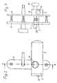
- a mortise lock 1 and an additional lock 2 are provided, this additional lock 2 once running horizontally across the width of the door and vertically across the height of the door.
- this additional lock 2 there are 7 lock boxes 28 on both sides of the door, into which the respective locking pins or bolts engage.
- a fitting consisting of an outer plate 5 and an inner plate 6 is used Inside the door, the housing 9 for the additional lock 2 is attached.
- the housing 9 is fastened to the inner shield 6 and forms a component with it.
- 2 and 3 is a simple box lock as an additional lock 2, the bolt 13 engages on the same side in a lock case, as well as the mortise lock.
- a rotary knob 11 is used on the inside of the door to actuate the mortise lock 1 and the additional lock 2, while the actuation takes place from the outside using a key 29.
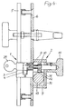
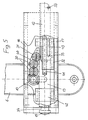
- FIGS. 4 and 5 The structure of the embodiment of such a device can be seen in particular in FIGS. 4 and 5, the knob profile cylinder on the mortise lock 1 being modified such that a knob shaft 8 is attached to the inside of the door and the locking lug 4, which is connected to a drive gear 10 .
- the locking nose 4 is inclined by approximately 45 ° mounted to the lock side to enable the locking bracket function and to generate a self-locking of the additional lock 2 against pushing back the bolts 13, 27, 26, 22.
- a plurality of intermediate gears 30 and an actuating gear 31 are provided, which are attached to a lever 40 which is fastened to the housing 9.
- the lever 40 can be used for right or left.
- the toothed wheel 31 engages in a toothed rack 12, on which the bolt 13 of the additional lock 2 is attached by means of a screw bolt 41.
- the rack 12 is widened relative to the gear 10 in order to compensate for different lock cylinder lengths.
- the mechanism of the additional lock 2 is arranged in the housing 9, two parallel strips 16, 17 being provided as the outer boundary, and in the case of a toothed rack 12 with a rectangular cross section, this is guided on the lower strip 17 (FIG. 4). To guide and reinforce the bracket or a toothed rack 12 (FIG.
- the bolt end 15 is provided with a groove 34.
- the mortise lock 1 When the mortise lock 1 is actuated with the aid of the key 29 or the rotary knob 11, the bolt 13 is first moved so far outward via the gearwheels 10, 30, 31 that the locking bracket 14 can hang in. Here, the door 7 can be opened by a gap width. To lock the door, the mortise lock 1 is then closed when the key 29 or the knob 11 is turned further, and at the same time the bolt 13 is moved into its closed position.
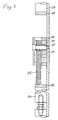
- the additional lock 2 extends over the entire width of the door, the housing 9 being extended accordingly (FIGS. 1 and 6).
- insert guides 35 are provided at the end.
- a connecting bracket 18 is attached to the end of the rack 12, which extends to the upper guide bar 16, a second rack 19 being fastened to this connecting bracket 18, which interacts with the upper guide bar 16.
- This rack 19 engages in a deflection gear 20 which is arranged on the housing 9, a third rack 21 engaging with this deflection gear 20, the movement of the two racks 19, 21 taking place in opposite directions.
- a second latch 22, the length of which is adjustable, is fastened to this toothed rack 21 via a connecting bracket 18.
- This latch 22 is arranged once on the lower guide bar 17 and on a further guide bar 36.
- This bolt 22 can engage in the right lock box 28 of the door frame. (Fig. 1).
- the vertically arranged additional lock 2 the parts of which are arranged in a housing 23 attached to the inside of the door, serves to further secure such a door.
- the mechanism has two toothed racks 24 and 25 arranged in opposite directions to the deflection gear 20, which are each fastened to connecting straps 18, which in turn are connected to further adjustable latches 26 and 27.
- These bolts 26 and 27 engage at the top and bottom of the door in corresponding lock boxes 28 on the door frame.
- all bolts 13, 22, 26, 27 and at the same time also the mortise lock are moved into the closed position or in the opening direction.
Abstract
Description
Die Erfindung betrifft eine Schließvorrichtung für Türen, bestehend aus einem Einsteckschloß und einem davon unabhängigen Zusatzschloß, wobei das Einsteckschloß mit seinem Knauf-Profilzylinder und seiner Schließnase zwischen einem Außen- und Innenschild eines Türbeschlages angeordnet ist.The invention relates to a locking device for doors, consisting of a mortise lock and an independent additional lock, the mortise lock with its knob profile cylinder and its locking lug being arranged between an outer and inner plate of a door fitting.
Zum Verschließen von Türen sind Einsteckschlösser bekannt, die mit einem Profilzylinder versehen sind. Weiterhin besitzen diese Schlösser eine Schließnase, mit der der Mechanismus für den Schließriegel betätigt wird. Neben diesen Einsteckschlössern werden zur Erhöhung der Sicherheit Kastenzusatzschlösser verwendet, die an der Innenseite der Türe befestigt werden, wobei ein Riegel nach Betätigen des Schlosses in einen Schließkasten eingreift. Diese Schlösser besitzen weiterhin einen Sperrbügel, der ein spaltbreites Öffnen der Türe ermöglicht. Bekannt sind weiterhin Querriegelschlösser, die über die gesamte Breite der Türe reichen und die zu beiden Seiten der Türe Riegel besitzen, die in entsprechende Schließkasten am Türrahmen eingreifen. Es gibt auch solche Schlösser, die an der Türhöhe angebracht werden und mit entsprechenden Riegeln am oberen bzw. unteren Ende der Türe verankert sind. Alle diese Schlösser haben für sich gesehen eigene Schließmechanismen und müssen jeweils zum Schließen und auch Öffnen gesondert betätigt werden, wobei dafür auch in der Regel unterschiedliche Schlüssel vorgesehen sind. Hierbei muß für jedes zusätzliche Schloß in der Türe eine Bohrung für den Profilzylinder vorgesehen werden, was montagetechnisch aufwendig ist.Mortise locks are known for closing doors, which are provided with a profile cylinder. Furthermore, these locks have a locking lug with which the mechanism for the locking bolt is actuated. In addition to these mortise locks, additional box locks are used to increase security, which are attached to the inside of the door, with a bolt engaging a lock case after the lock has been actuated. These locks also have a locking bracket, which enables the door to be opened wide. Cross bolt locks are also known which extend over the entire width of the door and which have bolts on both sides of the door which engage in corresponding lock boxes on the door frame. There are also such locks that are attached to the door height and are anchored with corresponding bolts at the top or bottom of the door. All of these locks have their own locking mechanisms and must be actuated separately for closing and opening, with different keys usually being provided for this. A hole for the profile cylinder must be provided for each additional lock in the door become what is technically complex.
Der Erfindung liegt die Aufgabe zugrunde, eine Schließvorrichtung vorzuschlagen, bei der mehrere Schlösser unter Verwendung eines Schließzylinders vereinigt bzw. betätigbar sind und hierbei die Stabilität erhöht und die Montage erleichtert wird.The invention is based on the object of proposing a locking device in which a plurality of locks can be combined or actuated using a locking cylinder, thereby increasing stability and facilitating assembly.
Diese Aufgabe wird nach der Erfindung dadurch gelöst, daß das Einsteckschloß und das Zusatzschloß mechanisch miteinander gekoppelt sind, indem in einem am Innenschild befestigten Gehäuse ein mit einem an der Türinnenseite angeordneten Drehknauf verbundenes Antriebszahnrad vorgesehen ist, das in eine in dem Gehäuse geführte Zahnstange eingreift, an der ein Riegel angebracht ist, und daß an der Schließnase eine Knaufwelle befestigt ist, die mit dem Antriebszahnrad verbunden ist.This object is achieved according to the invention in that the mortise lock and the additional lock are mechanically coupled to one another by a drive gearwheel connected to a rotary knob arranged on the inside of the door, which engages in a rack guided in the housing, is provided in a housing fastened to the inner plate. on which a bolt is attached, and that a knob shaft is attached to the locking lug, which is connected to the drive gear.
Vorteilhaft ist es, daß die Schließnase etwa 45o schräg nach unten zur Schloßseite montiert ist.It is advantageous that the locking cam is about 45 o mounted obliquely downward to the lock side.
Weiterhin ist es vorteilhaft, daß ein Sperrbügel angeordnet ist, der in das durch das Betätigungszahnrad vorgeschobene Riegelende einhängbar ist.Furthermore, it is advantageous that a locking bracket is arranged, which can be hooked into the bolt end advanced by the actuating gear.
Eine vorteilhafte Ausführungsform sieht vor, daß zwischen dem Antriebszahnrad und der Zahnstange Zwischenräder vorgesehen sind, die an einem am Gehäuse befestigten Hebel angeordnet sind.An advantageous embodiment provides that intermediate wheels are provided between the drive gear and the rack, which are arranged on a lever attached to the housing.
Weiterhin wird vorgeschlagen, daß der Riegel zu seinem Ende hin mittels einer am Gehäuse befestigten Buchse und am ent gegengesetzten Ende mittels einer weiteren Buchse gehaltert ist.It is also proposed that the latch towards its end by means of a socket attached to the housing and on ent opposite end is held by means of a further socket.
Es ist vorteilhaft, daß der Riegel mittels eines Schraubbolzens längenverstellbar mit der Zahnstange verbunden ist.It is advantageous that the bolt is connected to the rack by means of a screw which is adjustable in length.
Eine vorteilhafte Ausführungsform sieht vor, daß das Gehäuse über die gesamte Türbreite reicht und zwei zueinander parallele Leisten aufweist, wobei die Zahnstange an Buchsen geführt ist und an ihrem dem Riegel abgewandten Ende eine Verbindungslasche besitzt, an der eine zweite Zahnstange befestigt ist, die mit einem am Gehäuse angeordneten Umlenkzahnrad kämmt, das eine dritte Zahnstange mit einem daran befestigten zweiten Riegel antriebt.An advantageous embodiment provides that the housing extends over the entire width of the door and has two mutually parallel strips, the rack being guided on sockets and having a connecting tab on its end facing away from the bolt, to which a second rack is fastened, which is connected to a combs arranged on the housing deflection gear which drives a third rack with a second bolt attached to it.
Weiterhin wird vorgeschlagen, daß ein weiteres über die Türhöhe reichendes Gehäuse mit am Umlenkzahnrad eingreifenden weiteren Zahnstangen und weiteren verstellbaren Riegeln vorgesehen ist.Furthermore, it is proposed that a further housing reaching beyond the door height is provided with further toothed racks engaging on the deflection gear and further adjustable latches.
Die Erfindung bringt den Vorteil, daß unter Verwendung eines einzigen Knauf-Profilzylinders die verschiedenen Schließvorgänge sowohl an dem verwendeten Einsteckschloß als auch an den verschiedenen Zusatzschlössern, durchgeführt werden können. Es muß hierbei keine zusätzliche Bohrung für den Zylinder des Kastenschlosses vorgesehen werden. Die gesamte Schließeinrichtung läßt sich raumsparender unterbringen, ohne daß dadurch die Sicherheit der Schließeinrichtung vermindert wird. Der Innenbeschlag ist mit dem Gehäuse des Zusatzschlosses verbunden und wird so direkt montiert, indem das Innenschild mit dem Kastenschloß ausgewechselt bzw. angebracht wird. Diese Verbindung zwischen Gehäuse und Innen schild hat auch noch den Vorteil, daß das Türschild dadurch vollkommen versteift wird. Für das Anbringen des Zusatzschlosses werden damit auch keine zusätzlichen Bohrungen gebraucht, so daß eine derartige Kombination auch für feuerfeste Türen verwendbar ist. Ein weiterer wesentlicher Vorteil besteht darin, daß ein Knauf-Profilzylinder mit ein fachen Mitteln nachträglich so umgerüstet werden kann, daß er in der erfindungsgemäßen Einrichtung die Antriebsfunktion besitzt. Hierbei kann das Außenschild weiterverwendet werden. Durch die Befestigung an einem Sicherheitsaußenschild wird eine hohe Festigkeit erreicht. Weiterhin ist das Zusatzschloß auf links oder rechts umbaufähig.The invention has the advantage that the different locking operations can be carried out both on the mortise lock used and on the various additional locks using a single knob profile cylinder. There is no need to provide an additional hole for the cylinder of the box lock. The entire locking device can be accommodated in a space-saving manner without the security of the locking device being reduced thereby. The inner fitting is connected to the housing of the additional lock and is installed directly by replacing or attaching the inner plate with the box lock. This connection between the housing and the inside plate also has the advantage that the door plate is completely stiffened. No additional holes are required for attaching the additional lock, so that such a combination can also be used for fireproof doors. Another major advantage is that a Knauf profile cylinder can be retrofitted with a simple means so that it has the drive function in the device according to the invention. The outer plate can continue to be used. A high degree of strength is achieved by fastening to a security outer shield. Furthermore, the additional lock can be converted to the left or right.
Die Erfindung wird in der nachfolgenden Beschreibung anhand von in den Zeichnungen dargestellten Ausführungsbeispielen näher erläutert.The invention is explained in more detail in the following description with reference to exemplary embodiments shown in the drawings.
Es zeigen,
- Fig. 1 die Ansicht einer Türe mit verschiedenen anzubringenden Schlössern,
- Fig. 2 die Ansicht eines Türbeschlages mit einem zusätzlichen Kastenschloß,
- Fig. 3 eine Seitenansicht von Fig. 2,
- Fig. 4 einen Schnitt nach der Linie A-B in Fig. 2,
- Fig. 5 eine vergrößerte Ansicht gemäß Fig. 2 mit dem Antriebsmechanismus,
- Fig. 6 eine Ansicht des Antriebsmechanismus für weitere Zusatzschlösser und Riegel und
- Fig. 7 einen Schnitt nach der Linie C-D in Fig.6.
- 1 is a view of a door with different locks to be attached,
- 2 is a view of a door fitting with an additional box lock,
- 3 is a side view of FIG. 2,
- 4 shows a section along the line AB in FIG. 2,
- 5 is an enlarged view of FIG. 2 with the drive mechanism,
- Fig. 6 is a view of the drive mechanism for additional locks and bolts and
- Fig. 7 is a section along the line CD in Fig.6.
Zum Verschließen einer Türe 7 ist ein Einsteckschloß 1 sowie ein Zusatzschloß 2 vorgesehen, wobei dieses Zusatzschloß 2 einmal waagerecht über die Breite der Türe und senkrecht über die Höhe der Türe verläuft. Für dieses Zusatzschloß 2 befinden sich jeweils zu beiden Seiten der Türe 7 Schließkästen 28, in die die jeweiligen Schließzapfen bzw. Riegel einrasten. Zum Befestigen der Schlösser 1, 2 an der Türe dient insbesondere ein Beschlag, bestehend aus einem Außenschild 5 sowie einem Innenschild 6. Zwischen Außenschild 5 und Innenschild 6 ist das Einsteckschloß 1 mit seinem Knauf-Profilzylinder 3 und seiner Schließnase 4 montiert, während an der Innenseite der Türe das Gehäuse 9 für das Zusatzschloß 2 angebracht ist. Das Gehäuse 9 ist am Innenschild 6 befestigt und bildet mit diesem ein Bauteil. Bei dem in den Fig. 2 und 3 dargestellten Ausführungsbeispiel handelt es sich um ein einfaches Kastenschloß als Zusatzschloß 2, dessen Riegel 13 an der gleichen Seite in einen Schließkasten eingreift, wie auch das Einsteckschloß. Zum Betätigen des Einsteckschlosses 1 und des Zusatzschlosses 2 dient an der Türinnenseite ein Drehknauf 11, während die Betätigung von außen durch einen Schlüssel 29 erfolgt.To lock a
Der Aufbau der Ausführungsform einer derartigen Vorrichtung ist insbesondere aus den Fig. 4 und 5 ersichtlich, wobei der Knauf-Profilzylinder am Einsteckschloß 1 derart abgewandelt ist, daß zur Türinnenseite hinan der Schließnase 4 eine Knaufwelle 8 angebracht ist, die mit einem Antriebszahnrad 10 verbunden ist. Die Schließnase 4 ist um etwa 45° schräg zur Schloßseite hin montiert, um die Sperrbügelfunktion zu ermöglichen und eine Selbsthemmung des Zusatzschlosses 2 gegen ein Zurückdrücken der Riegel 13, 27, 26, 22 zu erzeugen. Für die Übertragung der Drehbewegung des Antriebszahnrades 10 auf einen Antriebsmechanismus des Zusatzschlosses 2 sind mehrere Zwischenzahnräder 30 und ein Betätigungszahnrad 31 vorgesehen, die an einem Hebel 40 angebracht sind, der am Gehäuse 9 befestigt ist. Der Hebel 40 ist für rechts oder links verwendbar. Das Zahnrad 31 greift in eine Zahnstange 12 ein, an der der Riegel 13 des Zusatzschlosses 2 mit Hilfe eines Schraubbolzens 41 angebracht ist. Die Zahnstange 12 ist gegenüber dem Zahnrad 10 verbreitert, um verschiedene Schließzylinderbaulängen auszugleichen. Der Mechanismus des Zusatzschlosses 2 ist in dem Gehäuse 9 angeordnet, wobei als äußere Begrenzung zwei parallele Leisten 16, 17 vorgesehen sind, und bei einer im Querschnitt rechteckigen Zahnstange 12 diese an der unteren Leiste 17 geführt ist (Fig. 4). Zur Führung und Verstärkung der Halterung bzw. einer im Querschnitt runden Zahnstange 12 (Fig. 5) für den Riegel 13 dient eine vordere am Gehäuse 9 befestigte Buchse 42 und eine hintere Buchse 32, an der in einem Schlitz 43 geführt ein Anschlagstift 33 zur Anlage kommt, um die Öffnungsstellung des Riegels 13 zu begrenzen. Zum Einhängen eines Sperrbügels 14 ist das Riegelende 15 mit einer Nut 34 versehen.The structure of the embodiment of such a device can be seen in particular in FIGS. 4 and 5, the knob profile cylinder on the
Beim Betätigen des Einsteckschlosses 1 mit Hilfe des Schlüssels 29 oder des Drehknaufes 11 wird zunächst über die Zahnräder 10, 30, 31 der Riegel 13 so weit nach außen bewegt, daß sich der Sperrbügel 14 einhängen kann. Hierbei läßt sich die Türe 7 um eine Spaltbreite öffnen. Zum Verschließen der Türe wird dann beim Weiterdrehen des Schlüssels 29 bzw. des Knaufes 11 das Einsteckschloß 1 geschlossen und gleichzeitig auch der Riegel 13 in seine Schließstellung bewegt.When the
Für eine weitere und zusätzliche Absicherung der Türe 7 reicht das Zusatzschloß 2 über die gesamte Breite der Türe, wobei das Gehäuse 9 entsprechend verlängert ist (Fig. 1 und 6). Zum Verlängern des Gehäuses bzw. der Führungschienen 16, 17 dienen am Ende vorgesehene Einsteckführungen 35. Weiterhin ist am Ende der Zahnstange 12 eine Verbindungslasche 18 angebracht, die bis zur oberen Führungsleiste 16 reicht, wobei an dieser Verbindungslasche 18 eine zweite Zahnstange 19 befestigt ist, die mit der oberen Führungsleiste 16 zusammenwirkt. Diese Zahnstange 19 greift in ein Umlenkzahnrad 20 ein, das am Gehäuse 9 angeordnet ist, wobei mit diesem Umlenkzahnrad 20 eine dritte Zahnstange 21 eingreift, wobei die Bewegung der beiden Zahnstangen 19, 21 entgegengesetzt erfolgt. An dieser Zahnstange 21 ist über eine Verbindungslasche 18 ein zweiter Riegel 22 befestigt, dessen Länge verstellbar ist. Dieser Riegel 22 ist einmal an der unteren Führungsleiste 17 und an einer weiteren Führungsleiste 36 angeordnet. Dieser Riegel 22 kann in den rechten Schließkasten 28 des Türrahmens eingreifen. (Fig. 1).For a further and additional securing of the
Zur weiteren Absicherung einer derartigen Türe dient das vertikal angeordnete Zusatzschloß 2, dessen Teile in einem an der Türinnenseite angebrachten Gehäuse 23 angeordnet sind. Der Mechanismus weist zwei zum Umlenkzahnrad 20 gegenläufig angeordnete Zahnstangen 24 bzw. 25 auf, die jeweils an Verbindungslaschen 18 befestigt sind, die ihrerseits mit weiteren verstellbaren Riegeln 26 bzw. 27 verbunden sind. Diese Riegel 26 bzw. 27 greifen am oberen bzw. unteren Ende der Türe in entsprechende Schließkästen 28 am Türrahmen ein. Bei dieser Ausführungsform werden sämtliche Riegel 13, 22, 26, 27 und gleichzeitig auch das Einsteckschloß in die Schließstellung bzw. in Öffnungsrichtung bewegt.The vertically arranged
Claims (8)
Applications Claiming Priority (2)
| Application Number | Priority Date | Filing Date | Title |
|---|---|---|---|
| DE3816341 | 1988-05-13 | ||
| DE19883816341 DE3816341A1 (en) | 1988-05-13 | 1988-05-13 | COMBINATION LOCK |
Publications (2)
| Publication Number | Publication Date |
|---|---|
| EP0341529A2 true EP0341529A2 (en) | 1989-11-15 |
| EP0341529A3 EP0341529A3 (en) | 1990-08-29 |
Family
ID=6354299
Family Applications (1)
| Application Number | Title | Priority Date | Filing Date |
|---|---|---|---|
| EP89107850A Withdrawn EP0341529A3 (en) | 1988-05-13 | 1989-04-29 | Cocking device |
Country Status (2)
| Country | Link |
|---|---|
| EP (1) | EP0341529A3 (en) |
| DE (1) | DE3816341A1 (en) |
Cited By (2)
| Publication number | Priority date | Publication date | Assignee | Title |
|---|---|---|---|---|
| US6035674A (en) * | 1995-03-07 | 2000-03-14 | Rittal-Werk Rudolf Loh Gmbh | Door locking device with several closing rods |
| EP2392754A1 (en) * | 2005-07-01 | 2011-12-07 | Daniels, Ron R. | Security system for entrance barriers |
Families Citing this family (5)
| Publication number | Priority date | Publication date | Assignee | Title |
|---|---|---|---|---|
| CH686261A5 (en) * | 1992-12-23 | 1996-02-15 | Schulte & Co Schlossfab | Lock mechanism. |
| EP0915220B1 (en) | 1997-11-06 | 2008-09-24 | Drumm GmbH | Electronic-mechanical locking system |
| DE20205146U1 (en) * | 2002-04-04 | 2003-05-15 | Drumm Gmbh | Universal door lock |
| DE102014018834A1 (en) | 2014-12-21 | 2016-06-23 | Gisbert Gorlt | door security |
| DE102016121601A1 (en) * | 2016-11-11 | 2018-05-17 | Wolfgang Göricke | Door with crossbar lock |
Citations (3)
| Publication number | Priority date | Publication date | Assignee | Title |
|---|---|---|---|---|
| BE424057A (en) * | ||||
| US2946214A (en) * | 1958-04-10 | 1960-07-26 | Gotay Erasmo | Double bolt lock means |
| FR1269754A (en) * | 1960-07-05 | 1961-08-18 | Safety closing device |
Family Cites Families (4)
| Publication number | Priority date | Publication date | Assignee | Title |
|---|---|---|---|---|
| FR327884A (en) * | 1902-12-31 | 1903-07-06 | Drouet Gustave | Closing device for doors, etc. |
| US932383A (en) * | 1908-10-14 | 1909-08-24 | Michael Furman | Door-bolt mechanism. |
| FR2385865A1 (en) * | 1977-03-31 | 1978-10-27 | Fichet Bauche | Door lock with horizontal bolt - has vertical finger plate coupled to vertical bar to adapt lock for use with vertical bolts |
| AT366750B (en) * | 1980-11-13 | 1982-05-10 | Grundmann Rohrbacher Schlosser | DOOR LOCK |
-
1988
- 1988-05-13 DE DE19883816341 patent/DE3816341A1/en active Granted
-
1989
- 1989-04-29 EP EP89107850A patent/EP0341529A3/en not_active Withdrawn
Patent Citations (3)
| Publication number | Priority date | Publication date | Assignee | Title |
|---|---|---|---|---|
| BE424057A (en) * | ||||
| US2946214A (en) * | 1958-04-10 | 1960-07-26 | Gotay Erasmo | Double bolt lock means |
| FR1269754A (en) * | 1960-07-05 | 1961-08-18 | Safety closing device |
Cited By (4)
| Publication number | Priority date | Publication date | Assignee | Title |
|---|---|---|---|---|
| US6035674A (en) * | 1995-03-07 | 2000-03-14 | Rittal-Werk Rudolf Loh Gmbh | Door locking device with several closing rods |
| EP2392754A1 (en) * | 2005-07-01 | 2011-12-07 | Daniels, Ron R. | Security system for entrance barriers |
| US8459704B2 (en) | 2005-07-01 | 2013-06-11 | Ron R. Daniels | Security system for entrance barriers |
| US9487975B2 (en) | 2005-07-01 | 2016-11-08 | Ron R. Daniels | Security systems for entrance barriers |
Also Published As
| Publication number | Publication date |
|---|---|
| DE3816341C2 (en) | 1993-02-18 |
| EP0341529A3 (en) | 1990-08-29 |
| DE3816341A1 (en) | 1989-11-23 |
Similar Documents
| Publication | Publication Date | Title |
|---|---|---|
| EP0666396B1 (en) | Security door and security device for installation in a door | |
| DE2831896C2 (en) | Gear drive in a cylinder-actuated espagnolette lock | |
| EP1049846B1 (en) | Door lock for an all-glass door with fixed glass side-element | |
| EP1921233A1 (en) | Retrofit actuating drive for a swing door or similar | |
| EP0341529A2 (en) | Cocking device | |
| EP0597170B1 (en) | Rotary bolt locking | |
| DE19507852C1 (en) | Door lock with several locking bars | |
| EP0573819B1 (en) | Window, door or similar with fittings for mounting in profiled multi-level wing grooves | |
| DE19652599A1 (en) | Swing door unit or fixed and passage doors with locks | |
| DE3937817C2 (en) | Lockable gear for window or door fittings | |
| DE102016118112A1 (en) | Device for increasing the stroke on a channel latch | |
| DE19523617C2 (en) | Espagnolette lock | |
| DE102012200640A1 (en) | Driving device for a joint operation of a central closure and the wing of a window or a door | |
| DE102010043821A1 (en) | Locking device for a side sectional door | |
| DE102015202853A1 (en) | door drive | |
| DE3015104C2 (en) | Espagnolette drive in an espagnolette lock | |
| AT394607B (en) | MULTIPLE LOCKING | |
| EP0298292A2 (en) | Door lock with sliding bolt and latch | |
| DE102020112148B3 (en) | Hinge lock | |
| AT247741B (en) | Drive for window and door shoot bolt locks | |
| DE3314882A1 (en) | Locking device for locking doors | |
| DE19828365C1 (en) | Lock assembly for an insulated door | |
| DE2020240B2 (en) | LOCK FOR A TILTING-TILT SASH OF A WINDOW, A DOOR OR DGL. | |
| EP2933416A1 (en) | Door drive | |
| DE19709492A1 (en) | Locking bar arrangement for mounting in a groove of a door leaf etc. |
Legal Events
| Date | Code | Title | Description |
|---|---|---|---|
| PUAI | Public reference made under article 153(3) epc to a published international application that has entered the european phase |
Free format text: ORIGINAL CODE: 0009012 |
|
| AK | Designated contracting states |
Kind code of ref document: A2 Designated state(s): AT BE CH DE ES FR GB GR IT LI LU NL SE |
|
| PUAL | Search report despatched |
Free format text: ORIGINAL CODE: 0009013 |
|
| AK | Designated contracting states |
Kind code of ref document: A3 Designated state(s): AT BE CH DE ES FR GB GR IT LI LU NL SE |
|
| STAA | Information on the status of an ep patent application or granted ep patent |
Free format text: STATUS: THE APPLICATION IS DEEMED TO BE WITHDRAWN |
|
| 18D | Application deemed to be withdrawn |
Effective date: 19910301 |