EP0341424A2 - Device for treating printed products - Google Patents
Device for treating printed products Download PDFInfo
- Publication number
- EP0341424A2 EP0341424A2 EP89106112A EP89106112A EP0341424A2 EP 0341424 A2 EP0341424 A2 EP 0341424A2 EP 89106112 A EP89106112 A EP 89106112A EP 89106112 A EP89106112 A EP 89106112A EP 0341424 A2 EP0341424 A2 EP 0341424A2
- Authority
- EP
- European Patent Office
- Prior art keywords
- carriage
- rail
- printed products
- carriages
- control device
- Prior art date
- Legal status (The legal status is an assumption and is not a legal conclusion. Google has not performed a legal analysis and makes no representation as to the accuracy of the status listed.)
- Granted
Links
Images


Classifications
-
- B—PERFORMING OPERATIONS; TRANSPORTING
- B65—CONVEYING; PACKING; STORING; HANDLING THIN OR FILAMENTARY MATERIAL
- B65H—HANDLING THIN OR FILAMENTARY MATERIAL, e.g. SHEETS, WEBS, CABLES
- B65H29/00—Delivering or advancing articles from machines; Advancing articles to or into piles
- B65H29/26—Delivering or advancing articles from machines; Advancing articles to or into piles by dropping the articles
- B65H29/28—Delivering or advancing articles from machines; Advancing articles to or into piles by dropping the articles from mechanical grippers
-
- B—PERFORMING OPERATIONS; TRANSPORTING
- B65—CONVEYING; PACKING; STORING; HANDLING THIN OR FILAMENTARY MATERIAL
- B65H—HANDLING THIN OR FILAMENTARY MATERIAL, e.g. SHEETS, WEBS, CABLES
- B65H39/00—Associating, collating, or gathering articles or webs
- B65H39/02—Associating,collating or gathering articles from several sources
- B65H39/06—Associating,collating or gathering articles from several sources from delivery streams
- B65H39/065—Associating,collating or gathering articles from several sources from delivery streams by collecting in rotary carriers
-
- B—PERFORMING OPERATIONS; TRANSPORTING
- B65—CONVEYING; PACKING; STORING; HANDLING THIN OR FILAMENTARY MATERIAL
- B65H—HANDLING THIN OR FILAMENTARY MATERIAL, e.g. SHEETS, WEBS, CABLES
- B65H2301/00—Handling processes for sheets or webs
- B65H2301/40—Type of handling process
- B65H2301/43—Gathering; Associating; Assembling
- B65H2301/434—In channels, e.g. in which the articles are substantially vertical or inclined
- B65H2301/4341—In channels, e.g. in which the articles are substantially vertical or inclined with several channels on a rotary carrier rotating around an axis parallel to the channels
-
- B—PERFORMING OPERATIONS; TRANSPORTING
- B65—CONVEYING; PACKING; STORING; HANDLING THIN OR FILAMENTARY MATERIAL
- B65H—HANDLING THIN OR FILAMENTARY MATERIAL, e.g. SHEETS, WEBS, CABLES
- B65H2301/00—Handling processes for sheets or webs
- B65H2301/40—Type of handling process
- B65H2301/44—Moving, forwarding, guiding material
- B65H2301/447—Moving, forwarding, guiding material transferring material between transport devices
- B65H2301/4471—Grippers, e.g. moved in paths enclosing an area
- B65H2301/44712—Grippers, e.g. moved in paths enclosing an area carried by chains or bands
Definitions
- the present invention relates to a device for processing, in particular for inserting, collating or collecting printed products, according to the preambles of patent claims 1 and 11.
- Such a device with a cellular wheel driven in rotation about a circumferential axis with compartments running in the direction of the circumferential axis is known, for example, from CH-PS 575,303 or the corresponding US Pat. No. 4,058,202.
- a carriage with controllable clamps is assigned to each compartment, which carries out a conveying and a return stroke in the course of one revolution of the cell wheel.
- feed points are provided one behind the other, at which printed products are introduced into the compartments and the trolleys are handed over for further transport to the next feed point or to the removal point arranged at the end of the cell wheel in the direction of the conveying stroke.
- a shaft running in the longitudinal direction of the compartments is pivotally mounted on each carriage, to which the clamping tongues of the clamps are resiliently attached.
- the shaft has an actuating member protruding radially towards the inside, which, when the carriage is stationary in the direction of the conveying stroke, runs onto a stationary closing link at the beginning of the conveying stroke, as a result of which the shaft is pivoted and the clamping tongues are transferred from their open position to the closing position.
- a freewheel which is operatively connected to the shaft prevents the shaft from pivoting back against the open position of the clamping tongues.
- brackets can be controlled independently of the movement or the position of the carriage. In addition to a simple mechanical structure, this also allows the same device to be used in a wide variety of ways, for example for inserting, collating and collecting printed products. It should be noted here that only a single processing route or multiple processing routes can be provided, along which the printed products are transported.
- a particularly simple embodiment of the control device seen in the direction of movement of the carriage, has stationary control means, by means of which, regardless of the position and ge speed of the car, the closing or opening commands can be transferred to the brackets.
- a particularly simple control device is defined in claim 3. It has a rail section which is displaceable transversely to the direction of movement of the carriage and in which an actuating element for the clamps which is arranged on the carriage is guided.
- the actuator can thus be operated in a simple manner regardless of the position of the car.
- a preferred embodiment for the storage and actuation of the rail piece is specified in claim 9.
- a particularly high processing capacity can be achieved if, according to claim 11, a cellular wheel is equipped with carriages which have clamps which can be controlled by means of the control device, independently of the movement and position of the carriages.
- the brackets can be controlled in a particularly simple manner in that each rail section is operatively connected to a follower which slides on a fixed backdrop, the brackets being able to be influenced solely as a function of the rotational position of the cellular wheel.
- the possible uses and adjustability of the cellular wheel can be improved in that this backdrop can be exchanged for another backdrop, or in that its position or shape can be changed.
- FIG 1 shows a cell wheel-like collating drum 12 which is rotatably mounted on a frame 10 and can be driven in a rotating manner, with a plurality of pocket-shaped compartments 14 which extend in the longitudinal direction of the drum 12 and which together rotate in the arrow direction U about a rotation axis 16.
- a hollow axis 18 is arranged on the frame 10, the longitudinal axis of which coincides with the circumferential axis 16.
- Spoked wheels 20 (axially spaced from one another in FIG 1 only one visible) rotatably mounted.
- On the rings 22 of the spoke wheels 20 are in the longitudinal direction of the drum 12 extending, projecting in the radial direction outwardly projecting partitions 24 which, seen in the direction of rotation U, separate the compartments 14 from each other.
- feed conveyors 26 which are spaced apart from one another in the direction of the axis of rotation 16 and which can be driven synchronously by means of a common drive shaft 28.
- a removal conveyor 30 is arranged, which is also only shown schematically.
- the feed conveyors 26 have individually controllable grippers 32 which are arranged on a pulling element (not shown) which is driven in a rotating manner in the feed direction Z and which are also shown only hinted at.
- Such feed conveyors 26 are generally known and can be constructed, for example, the same or similar to the feed conveyors shown in EP-OS 0 218 872 or the corresponding US Pat. No. 4,706,951.
- Each gripper 32 guided to the collating drum 12 holds a printing sheet 34 at its trailing edge 36 as seen in the feed direction Z.
- the drum 12 is preceded by a guide plate 38, which runs essentially parallel to the feed direction Z and is arranged below the feed conveyor 26 and which guides the leading slide sliding on it Edges of the printed sheets 34 into the respective compartments 14.
- the removal conveyor 30 also has a gripper 32 which is arranged on a rotating pulling element (not shown) which is driven in the removal direction W and which grips the conveyed printed sheets 34 and conveys them away.
- a gripper 32 which is arranged on a rotating pulling element (not shown) which is driven in the removal direction W and which grips the conveyed printed sheets 34 and conveys them away.
- a similar conveyor is described in more detail, for example, in Swiss Patent 584,153 and the corresponding US Patent 3,951,399.
- Each printed sheet 34 held by a gripper 32 of the feed conveyor 26 is introduced by the guide plate 38 into a compartment 14 of the collating drum 12 and dropped by the gripper 32 as soon as it has reached a position approximately perpendicularly above the rotation axis 16.
- the printed sheets 34 thus dropped come to rest on the bottom of the respective compartment 14.
- the first feed conveyor 26 conveys a printed sheet 34 in the course of the revolutions of the drum 12 in the direction of rotation U into each compartment 14 passing under this feed conveyor 26.
- FIG. 2 shows part of the collating drum 12 in a longitudinal section.
- the one spoked wheel 20 visible in FIG. 2 is rotatably mounted on the hollow axle 18, and a sprocket 42 of a chain drive, which is operatively connected to a drive motor, not shown, is seated on its hub 40 in a rotationally fixed manner.
- the drum 12 is driven in the direction of rotation U by means of this drive motor (cf. FIG. 1).
- a rail 44 with a C-shaped cross section which extends in the longitudinal direction of the collating drum 12 and which, together with the support 46 fastened thereon, forms a partition wall 24. All partition walls 24 shown in FIG. 1 are constructed in the same way as partition wall 24 shown in FIG. 2.
- Each carriage 50 which are visible in FIG. 2 and are connected to one another by means of coupling members 48, are guided in rail 44.
- Each carriage 50 has three or two pairs of guide rollers 52 rotatably mounted on it, which run in the rail 44.
- two clamping tongues 54 are pivotally mounted, which can be transferred from their open position to the closed position and back by means of rail pieces 56 of a control device 58 which are coupled to one another. This is described in more detail below.
- each rail section 56 is mounted on two parallel pivot levers 60, which in turn are pivotably mounted on the rail 44.
- the Darge at the left end of the rail 44 posed and designated 60 'pivoting lever is designed as an angle lever and is connected via a connecting rod 62 with a, on the rim 22 pivotally mounted two-armed control lever 64 in operative connection, at the other end a follower roller 66 is rotatably mounted, which in turn on a guide surface of a fixed backdrop 68 rolls.
- One at one end attached to the rail 44 and the other on the pivot lever 60 'acting compression spring 70 presses the follower roller 66 against the guide surface of the link 68 and at the same time biases the clamping tongues 54 against the open position.
- a coaxial control cylinder 72 is provided in the initial region of the collating drum 12, on the usually stationary hollow axis 18, which is arranged in a rotationally fixed manner and whose outer surface is spaced from the inside, as seen in the radial direction, by the rails 44.
- a self-contained, like an ellipse, around the control cylinder 72 encircling control link 74 is arranged, which seen in the direction of the axis of rotation 16, in each of the end regions a strong curvature and between these end regions each with an area with respect to the direction of rotation U has constant slope (only part of the control link 74 is indicated in FIG. 2).
- bracket 76 With all of the carriages 50 guided in a rail 44, only the carriage 50 in the area of the control cylinder 72 has a bracket 76 with which it is connected to one of the carriages 50 which are adjacent in the direction of rotation U.
- a driver 78 arranged on the bracket 76 runs in the control link 74 on the control cylinder 72 animals on the floor of the carriage 50, indicated by the clamping tongues 54 printed sheets 34 are indicated, viewed in the conveying direction F, starting from the left, the first three printed sheets 34 shown in FIG. 2 essentially coincide with the position of the feed conveyors 26 (see Fig. 1).
- the first clamping tongue 54 holds a single printed sheet 34 inserted by the first feed conveyor 26
- the second clamping tongue 54 has its two congruent printed sheets 34, the second being fed by the second feed conveyor 26, and the third clamping tongue 54 there are three, the third was fed by the third feeder 26.
- Each of the next following clamping tongues 54 also clamps three printing sheets 34 standing side by side.
- FIG. 3 shows part of the left half of FIG. 2 in perspective and on an enlarged scale, the carriage 50 being shown partially cut away.
- the same parts are given the same reference numerals as in FIG. 2. It will only be dealt with to the extent necessary for understanding FIG. 3.
- the opposite ends of the C-shaped rail 44 each carry a guide profile 80, for example made of plastic.
- the rollers of the guide roller pairs 52, which are rotatably mounted on the carriage 50, are concave, so that they partially encompass the guide profile 80 and give the carriage 50 a secure hold in a direction perpendicular to the rail 44.
- the pivot levers 60, 60 ' are pivotally mounted, the free ends of which are pivotally connected to the rail section 56.
- the rail piece 56 is also in the cross cut C-shaped, wherein in the region of the pivot lever 60, 60 'the upper edge 56' is excluded.
- the connecting piece, which connects the rail section 56 to the next following rail section 56, viewed in the direction F, is identified by 82.
- the rail piece 56 makes a movement, such as the coupling of a parallel crank mechanism and thus also a lifting movement in the direction of arrow H, ie in the radial direction towards the outside.
- This movement of the rail section 56 is controlled by the sliding roller 66 on the link 68, the movement of which is transmitted by means of the control lever 64 and the connecting rod 62 to the pivot lever 60 'designed as an angle lever.
- the carriage 50 has a flat wall element 84 on which the pairs of guide rollers 52 are mounted.
- a flat wall element 84 on which the pairs of guide rollers 52 are mounted.
- an upwardly angled guide element 86 which forms a pocket with a bottom and which is cut out in the region of the clamping tongues 54.
- the clamping tongues 54 which are preferably made of spring steel, are fastened to a shaft 90 which runs in the longitudinal direction of the rail 44 and is pivotably mounted on the wall element 84 by means of bearing elements 88.
- the free ends of the clamping tongues 54 projecting upwards can carry clamping supports, for example made of rubber.
- a lever arm 92 projecting against the rail section 56 is fastened to the shaft 90, at the free end of which a roller 94 guided in the C-shaped rail section 56 is rotatable is stored.
- the roller 94 slides in the rail section 56 and when the rail section 56 is raised or lowered in or against the arrow direction H, the two clamping tongues 54 are pivoted in the open or in the closed position.
- the carriage 50 makes a conveying stroke in the direction of the arrow F and a return stroke in the opposite direction in accordance with the control link 74 in which the driver 78 slides.
- the individual printed sheets 34 or placed side by side on the bottom of the guide element 86 are indicated by dash-dotted lines (the printed sheets 34 shown on the right in FIG. 3 are shown cut off on the right side).
- FIG. 4 shows a section along the line IV-IV of FIG. 2 through several compartments 14 of the gathering drum 12 (cf. FIG. 1).
- the rails 44 are fastened on the rim 22 of the spoke wheel 20 (see FIGS. 1 and 2), and the cross-sectionally saddle-shaped supports 46 are seated on them in the radial direction towards the outside.
- the guide profiles 80 are arranged on the mutually directed ends of each rail 44 , on which the guide roller pairs 52 are guided.
- the pairs of guide rollers 52 are rotatably mounted on the respective wall element 84, and on this the guide element 86 and the bearing elements 88, of which only one is visible in each case in FIG. 4, are fastened.
- the upper end of the guide element 86 extends behind the leading edge 46 'of the trailing support 46.
- the top of the Wall element 84 covered by the corresponding support 46, so that the printed sheets 34, 34 'when shooting into the pocket formed by the wall element 84 and guide element 86 can easily reach the bottom thereof and thus in the area of the clamping tongues 54.
- the clamping tongues 54 are fastened to the shafts 90 mounted on the bearing elements 88, from which the lever arms 92 protrude against the rail pieces 56.
- a roller 94 is rotatably mounted, which is guided in the respective rail section 56 and has a convex tread.
- the rail piece 56 shown on the right in FIG. 4 is located in the direction of arrow H in the upper end position in the radial direction, so that the relevant clamping tongues 54 are in their open position, in which the free ends of the clamping tongues 54 are seen in the direction of rotation U. , come to rest behind the guide element 86.
- the rail piece 56 shown on the left in this figure is located in the lower, radially inner end position counter to the direction of arrow H, as a result of which the corresponding clamping tongues 54 are transferred to the closed position in which they clamp the printed sheets 34 between themselves and the counter-stop formed by the wall element 84.
- the opposite positions of the clamping tongues 54, rails 44 and rollers 94 are indicated by dash-dotted lines.
- the two carriages 50 shown in FIG. 4 are operatively connected to one another by means of the bracket 76, the rail sections 56 of these two Wagons 50 can be controlled independently of each other.
- the driver 78 has a roller which is guided on two round profiles which are arranged in parallel on the control cylinder 72 and have a circular cross section and whose opposing surfaces form the control link 74.
- the coupling members are designated by 48, by means of which the carriages 50 guided in a rail 44 are coupled to one another (cf. FIG. 2).
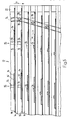
- Fig. 5 shows that part of the conveying path of the printed sheets 34, 34 ', which, seen in the direction of rotation U, follows the two in the direction of arrow F of Fig. 1 first feeders 26. 5, these two feed conveyors are indicated by arrows denoted by 26.
- the structure of the collating drum 12 is indicated in a highly simplified manner.
- the supports 46 arranged on the rails 44 are not shown.
- only the wall elements 84 and clamping tongues 54 of the carriages 50 are shown.
- the catches 78 are shown which slide in the fixed control link 74.
- the clamping tongues 54 of the wall elements 84 which are each connected to one another by means of a bracket 76, as seen in the direction of the arrow F, are at the same height.
- the direction of rotation is designated by U.
- the gathering drum 12 functions as follows:
- the first feed conveyor 26 seen in the direction of the arrow F leads into each one below it in the direction of the arrow U passing compartment 14 a printing sheet 34. This falls with the clamping tabs 54 in the open position on the floor of the carriage 50 concerned.
- the clamping tabs 54 are transferred to the closed position, whereby the respective printing sheet 34 between the clamping tongue 54th and the wall element 84 is clamped and taken in the conveying direction F in accordance with the control link 74.
- a helical conveying path to the next feed conveyor 26 is thus formed, the conveying stroke in the direction of arrow F essentially taking place when passing through the lower half of the conveying path (cf.
- FIG. 1 As soon as a compartment 14 reaches the upper region of the orbit in the course of one revolution, the clamping tongues 54 in question are moved into the open position and the return stroke is initiated in the opposite direction of arrow F for the carriages 50 in question.
- these printed sheets 34 arrive at the second feed conveyor 26, where the latter feeds a second printed sheet 34 'into each compartment next to the already existing printed sheets 34 (see in particular FIG. 5).
- the two adjacent printing sheets 34, 34 ' are now detected in the course of further rotation by the closing clamping tongues 54 and conveyed in the course of one revolution to the third feed conveyor 26, where a third printing sheet 34 is added in an analogous manner.
- each of these three adjacent printed sheets 34, 34 ' is conveyed to the conveyor 30, where they are gripped by the grippers 32 and conveyed away in the direction of the arrow W (see FIG. 1).
- pivotally mounted cantilevers can be provided, which during transport of the printed sheets 34, 34' in Arrow direction F are pivoted back by these and which, however, in the event of movement of the printed sheets 34, 34 'counter to the arrow direction F, put them in the way.
- Such cantilevers are known, for example, from the above-mentioned CH-PS 575,303 or the corresponding US-PS 4,058,202. It should be noted that when collating sheets 34, 34 'they may or may not be folded. It is also possible that the printed sheets 34 or 34 'fed from a feed conveyor 26 are folded, and the sheets 34 or 34' fed from another are not folded.
- Each of the folded printed sheets 34 and 34 'shown in FIGS. 1 to 4' consists of a plurality of folded single sheets, which are fed to the gathering drum 12 with their fold ahead.
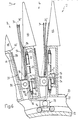
- the same drum 12 is shown in FIG. 6 in the same representation as in FIG. 4, but now further printing sheets 34 ′ are inserted into a first fed, folded printing sheet 34. In this case, it is therefore a plug-in drum 12.
- FIG. 6 For the detailed description of FIG. 6, reference is made to FIG. 4 and its description, since the structure of the device in these two figures corresponds to one another.
- the insert drum 12 (FIG. 6) functions as follows: the first feed conveyor 26 (FIG. 1) seen in the direction of arrow F introduces a folded printed sheet 34 into each compartment 14, with its fold 96 (FIG. 6) ahead.
- the printing sheet 34 When the grippers 32 are opened, the printing sheet 34, with the clamping tongues 54 in the open position, falls onto the bottom of the compartment 14 formed by the guide element 86.
- the relevant ones Clamping tongues 54 transferred to the closed position, so that the folded printed sheet 34 is held between the wall element 84 and a clamping tongue 54.
- the carriage 50 together with the printed sheet 34 is conveyed in the direction of arrow F into the area of the second feed conveyor 26 (see FIG. 1).
- the folded printed sheets 34 are opened by means of an opening device as described, for example, in CH-PS 641.113 or CH-PS 644.814 or the corresponding US-PS 4,398,710.
- the clamping tongues 54 are opened, and then a printed sheet 34 ⁇ , which can be folded or unfolded, is inserted into the opened folded printed sheet 34 by the second feeder 26.
- the printed sheets 34, 34 ⁇ thus inserted into one another are now held by the clamping tongues 54 and conveyed to the third feed conveyor 26, where a second printed sheet 34 ⁇ is inserted in an analogous manner.
- This second sheet 34 ⁇ can either next to or in the likewise open first sheet 34 ⁇ in the folded Sheet 34 are introduced.
- the printed sheets 34, 34 ⁇ which are nested in this way are transported in the course of two further rotations in the direction of arrow U to the conveyor 30, where they are gripped by the grippers 32 and conveyed away.
- Booms can also be provided in the insertion drum 12, as described in connection with the collating drum, in order to prevent the printed sheets 34, 34 ′ from running back in the opposite direction of the arrow F when the carriages 50 are lifted back.
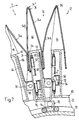
- FIG. 7 shows another possible use of the drum 12, namely for collecting folded printed sheets 34, 34 ′′′.
- the structure of the drum 12 used as a collecting drum corresponds to the structure of the collation drum according to FIG. 4.
- FIG. 4 A detailed description of this collecting drum 12 and its mode of operation is contained in the simultaneous Swiss patent application No. 01 795 / 88-0.
- the first feed conveyor 26 shown in FIG. 1, viewed in the direction of the arrow F, is placed on each support 46 in the same or similar manner, as is known, for example, from EP-OS 0 208 081 or the corresponding US Pat. No. 4,684,117 folded printed sheet 34 laid astride, so that each printed sheet half 34a or 34b comes to rest in a compartment 14.
- each printed sheet 34 is now held and transported on its printed sheet halves 34a, 34b by a carriage 50 arranged in different compartments 14.
- the corresponding clamping tongues 54 are opened, as a result of which the offset printed sheets 34 are realigned in an analogous manner, so that the second feed conveyor 26 in turn applies a folded printed sheet 34 ′′′ onto the support 46 stored sheet 34 can deposit.
- the printing sheets 34, 34 ′′′ lying one above the other are now clamped to their leading and then also to their trailing printing sheet halves 34a and 34b and conveyed in the course of the next rotation to the next feed conveyor 26, where a third printing sheet 34 ′′′ is placed astride the first two .
- the printed sheets 34, 34 so thus collected are transported to the conveyor 30, where they are gripped at their folded edges 96 and conveyed away.
- the opening device required for inserting printed sheets 34 'into a first folded printed sheet 34 (FIG. 6) and the delivery arms, which prevent the printed sheets 34, 34' from being taken along in the opposite direction of the arrow F when the carriage 50 is lifted back, can be arranged firmly on the drum 12 be, in particular the opening device must be designed so that it does not act on the printed sheets 34, 34 ⁇ when collating or collecting.
- opening devices could be arranged on the supports 46 such that they can be pivoted back into the supports 46.
- the opening devices and / or arms are removably arranged on the drum 12, so that the drum 12 can be converted for gathering, plugging in or collecting within short changeover times.
- the carriage 50 and control device 58 are of the same design for all processing purposes.
- the independence of the control device 58 from the drive device 72, 74, 76, 78 enables the closing or opening of the clamping tongues 54 to be adapted with little effort with regard to the movement or position of the carriage 50.
- the conveying or return stroke of the carriages 50 can also be adjusted by pivoting the hollow axis 18.
- the drum 12 (see FIG. 1) can, as viewed in the direction of the arrow F, be composed of sections. So it is quite conceivable that further such sections are added to the drum 12 shown in FIG. 1 in the opposite direction of the arrow F in order to collect, collect or insert more than three printed sheets 34, 34 ', 34 ⁇ , 34 ′′′.
- each printed sheet 34, 34 ', 34 ⁇ , 34 ′′′ can be held by more than one clamping tongue 54. It is also conceivable that each feed conveyor 26 feeds a plurality of printing sheets 34, 34 ′, 34 ⁇ or 34′′′ arranged one inside the other.
- the rail pieces 56 can, for example, also be L-shaped. This is particularly the case when the lever arms 92 are biased in a pivoting direction and the rollers 94 press against the one flank of the rail pieces 56.
- the movement of the rail pieces 56 can also take place in a direction other than in the radial direction H. It only has to be directed transversely to the direction of movement of the carriages 50.
- feed conveyor 26 could be replaced by known feeders, which feed the printed sheets 34, 34 ', 34 ⁇ , 34 ′′′ to the supports 46 or compartments 14.
Abstract
Description
Die vorliegende Erfindung betrifft eine Einrichtung zum Verarbeiten, insbesondere zum Einstecken, Zusammentragen oder Sammeln von Druckereiprodukten gemäss den Oberbegriffen der Patentansprüche 1 und 11.The present invention relates to a device for processing, in particular for inserting, collating or collecting printed products, according to the preambles of patent claims 1 and 11.
Eine solche Einrichtung mit einem um eine Umlaufachse drehend angetriebenen Zellenrad mit in Richtung der Umlaufachse verlaufenden Abteilen ist beispielsweise aus der CH-PS 575.303 bzw. der entsprechenden US-PS 4,058,202 bekannt. Jedem Abteil ist ein Wagen mit steuerbaren Klammern zugeordnet, welcher im Zuge einer Umdrehung des Zellenrades einen Förder- und einen Rückhub ausführt. In Längsrichtung des Zellenrades sind hintereinander Zuführstellen vorgesehen, an welchen Druckereiprodukte in die Abteile eingeführt und den Wagen zum Weitertransport zur nächsten Zuführstelle bzw. zur in Richtung des Förderhubs am Ende des Zellenrades angeordneten Entnahmestelle übergeben werden. An jedem Wagen ist eine in Längsrichtung der Abteile verlaufende Welle schwenkbar gelagert, an welcher die Klemmzungen der Klammern federnd befestigt sind. Die Welle weist ein, in radialer Richtung gegen innen vorstehendes Betätigungsorgan auf, welches bei in Richtung des Förderhubs stillstehendem Wagen am Anfang des Förderhubes auf eine ortsfeste Schliesskulisse aufläuft, wodurch die Welle verschwenkt und die Klemmzungen von ihrer Offenstellung in die Schliessstellung überführt werden. Ein mit der Welle wirkverbundener Freilauf verhindert ein Zurückschwenken der Welle gegen die Offenstellung der Klemmzungen. Diese bleiben während des Förderhubes des Wagens geschlossen, bis bei am Ende des Förderhubes stillstehendem Wagen ein Betätigungselement des Freilaufs im Zuge der Weiterdrehung des Zellenrades auf eine Oeffnungskulisse aufläuft, wodurch der Freilauf gelöst und die Welle in die Offenstellung der Klemmzungen zurückgeschwenkt wird. Diese Steuerungseinrichtung für die Klammern ist sehr aufwendig in ihrer Konstruktion und das Oeffnen und Schliessen der Klammern ist starr mit der Position des Wagens und der Drehung des Zellenrades gekoppelt.Such a device with a cellular wheel driven in rotation about a circumferential axis with compartments running in the direction of the circumferential axis is known, for example, from CH-PS 575,303 or the corresponding US Pat. No. 4,058,202. A carriage with controllable clamps is assigned to each compartment, which carries out a conveying and a return stroke in the course of one revolution of the cell wheel. In the longitudinal direction of the cell wheel, feed points are provided one behind the other, at which printed products are introduced into the compartments and the trolleys are handed over for further transport to the next feed point or to the removal point arranged at the end of the cell wheel in the direction of the conveying stroke. A shaft running in the longitudinal direction of the compartments is pivotally mounted on each carriage, to which the clamping tongues of the clamps are resiliently attached. The shaft has an actuating member protruding radially towards the inside, which, when the carriage is stationary in the direction of the conveying stroke, runs onto a stationary closing link at the beginning of the conveying stroke, as a result of which the shaft is pivoted and the clamping tongues are transferred from their open position to the closing position. A freewheel which is operatively connected to the shaft prevents the shaft from pivoting back against the open position of the clamping tongues. These remain closed during the conveying stroke of the carriage until, when the carriage is at the end of the conveying stroke, an actuating element of the freewheel runs onto an opening backdrop in the course of further rotation of the cellular wheel, whereby the freewheel is released and the shaft is pivoted back into the open position of the clamping tongues. This control device for the clamps is very complex in its construction and the opening and closing of the clamps is rigidly coupled with the position of the carriage and the rotation of the cell wheel.
Es ist daher Aufgabe der vorliegenden Erfindung, eine Einrichtung gemäss dem Oberbegriff des Anspruchs 1 bzw. 11 zu schaffen, welche einfacher im Aufbau und mit einfachen Mitteln einstellbar ist.It is therefore an object of the present invention to provide a device according to the preamble of claims 1 and 11, which can be set up more simply and with simple means.
Diese Aufgabe wird durch die Merkmale des kennzeichnenden Teils des Anspruchs 1 bzw. 11 gelöst. Die Klammern sind unabhängig von der Bewegung bzw. der Position des Wagens steuerbar. Neben einem einfachen mechanischen Aufbau erlaubt dies auch die verschiedensten Einsatzmöglichkeiten derselben Einrichtung, beispielsweise für das Einstecken, das Zusammentragen und das Sammeln von Druckereiprodukten. Dabei ist zu beachten, dass nur ein einziger Verarbeitungsweg oder mehrere Verarbeitungswege vorgesehen sein können, entlang welchen die Druckereiprodukte transportiert werden.This object is solved by the features of the characterizing part of claims 1 and 11, respectively. The brackets can be controlled independently of the movement or the position of the carriage. In addition to a simple mechanical structure, this also allows the same device to be used in a wide variety of ways, for example for inserting, collating and collecting printed products. It should be noted here that only a single processing route or multiple processing routes can be provided, along which the printed products are transported.
In bevorzugter Weise weist eine besonders einfache Ausführungsform der Steuerungseinrichtung, in Bewegungsrichtung des Wagens gesehen, stillstehende Steuermittel auf, mittels welchen, unabhängig von der Lage und Ge schwindigkeit des Wagens, die Schliess- bzw. die Oeffnungsbefehle an die Klammern übertragbar sind.In a preferred manner, a particularly simple embodiment of the control device, seen in the direction of movement of the carriage, has stationary control means, by means of which, regardless of the position and ge speed of the car, the closing or opening commands can be transferred to the brackets.
Eine besonders einfache Steuerungseinrichtung ist in Anspruch 3 definiert. Sie weist ein Schienenstück auf, welches quer zur Bewegungsrichtung des Wagens verschiebbar ist und in welchem ein am Wagen angeordnetes Betätigungsorgan für die Klammern geführt ist. Das Betätigungsorgan kann somit in einfacher Weise unabhängig von der Position des Wagens betätigt werden.A particularly simple control device is defined in claim 3. It has a rail section which is displaceable transversely to the direction of movement of the carriage and in which an actuating element for the clamps which is arranged on the carriage is guided. The actuator can thus be operated in a simple manner regardless of the position of the car.
Eine bevorzugte Ausführungsform für die Lagerung und Betätigung des Schienenstücks ist in Anspruch 9 angegeben.A preferred embodiment for the storage and actuation of the rail piece is specified in claim 9.
Eine besonders hohe Verarbeitungskapazität kann erreicht werden, wenn gemäss Anspruch 11 ein Zellenrad mit Wagen ausgerüstet wird, welche Klammern aufweisen, welche mittels der Steuerungseinrichtung, unabhängig von der Bewegung und Lage der Wagen, steuerbar sind.A particularly high processing capacity can be achieved if, according to claim 11, a cellular wheel is equipped with carriages which have clamps which can be controlled by means of the control device, independently of the movement and position of the carriages.
In besonders einfacher Weise sind die Klammern dadurch steuerbar, dass jedes Schienenstück mit einem Folgeglied wirkverbunden ist, welches an einer ortsfesten Kulisse gleitet, wobei die Klammern alleine in Abhängigkeit von der Drehlage des Zellenrades beeinflussbar sind. Die Einsatzmöglichkeiten und Einstellbarkeit des Zellenrades lassen sich dadurch verbessern, dass diese Kulisse gegen eine andere Kulisse austauschbar ist, oder dass sie in ihrer Lage bzw. ihrer Form veränderbar ist.The brackets can be controlled in a particularly simple manner in that each rail section is operatively connected to a follower which slides on a fixed backdrop, the brackets being able to be influenced solely as a function of the rotational position of the cellular wheel. The possible uses and adjustability of the cellular wheel can be improved in that this backdrop can be exchanged for another backdrop, or in that its position or shape can be changed.
Weitere bevorzugte Ausbildungsformen sind in den weiteren abhängigen Ansprüchen angegeben.Further preferred forms of training are specified in the further dependent claims.
Die Erfindung wird nun anhand eines in der Zeichnung dargestellten Beispiels näher beschrieben. Es zeigen rein schematisch:
- Fig. 1 in perspektivischer Darstellung ein Ausführungsbeispiel einer Zusammentragtrommel,
- Fig. 2 einen Teil der Zusammentragtrommel in einem Längsschnitt,
- Fig. 3 perspektivisch und vereinfacht dargestellt einen Teil der Fig. 2,
- Fig. 4 in vergrösserter Darstellung einen Schnitt entlang der Linie IV-IV der Fig. 2,
- Fig. 5 eine Abwicklung eines Teils des Förderweges der Druckbogen, und
- Fig. 6 und 7 in gleicher Darstellung wie Fig. 4 eine Einsteck- bzw. Sammeltrommel
- 1 is a perspective view of an embodiment of a collating drum,
- 2 shows a part of the collating drum in a longitudinal section,
- 3 is a perspective and simplified representation of part of FIG. 2,
- 4 is an enlarged view of a section along the line IV-IV of FIG. 2,
- Fig. 5 is a development of part of the path of the printed sheet, and
- 6 and 7 in the same representation as Fig. 4 an insertion or collecting drum
Fig. 1 zeigt eine an einem Gestell 10 drehbar gelagerte, umlaufend antreibbare zellenradartige Zusammentragtrommel 12 mit einer Vielzahl von in Längsrichtung der Trommel 12 sich erstreckenden, taschenförmigen Abteilen 14, die gemeinsam um eine Umlaufachse 16 in Pfeilrichtung U umlaufen. Am Gestell 10 ist eine Hohlachse 18 angeordnet, deren Längsache mit der Umlaufachse 16 zusammenfällt. An der Hohlachse 18 sind voneinander in Axialrichtung beabstandete Speichenräder 20 (von ihnen ist in der Fig. 1 nur eines sichtbar) drehbar gelagert. An den Kränzen 22 der Speichenräder 20 sind in Längsrichtung der Trommel 12 verlaufende, in radialer Richtung gegen aussen vorstehende Trennwände 24 befestigt, welche in Umlaufrichtung U gesehen die Abteile 14 voneinander trennen.1 shows a cell wheel-like collating
Oberhalb der Trommel 12 sind drei voneinander in Richtung der Umlaufachse 16 beabstandete, schematisch dargestellte Zuförderer 26 vorgesehen, welche mittels einer gemeinsamen Antriebswelle 28 synchron antreibbar sind. Im einen Endbereich der Zusammentragtrommel 12, in Richtung des Pfeiles F gesehen, ist ein Wegförderer 30 angeordnet, welcher ebenfalls nur schematisch dargestellt ist. Die Zuförderer 26 weisen an einem nicht dargestellten, in Zuführrichtung Z umlaufend angetriebenen Zugorgan angeordnete, einzeln steuerbare Greifer 32, welche auch nur andeutungsweise gezeigt sind. Solche Zuförderer 26 sind allgemein bekannt und können beispielsweise gleich oder ähnlich aufgebaut sein, wie die in der EP-OS 0 218 872 bzw. der entsprechenden US-PS 4,706,951 gezeigten Zuförderer. Es wäre auch denkbar, die Zuförderer 26 so auszubilden, wie dies in der CH-PS 575.303 bzw. der entsprechenden US-PS 4,058,202 offenbart ist. Jeder zur Zusammentragtrommel 12 geführte Greifer 32 fasst einen Druckbogen 34 an dessen in Zuführrichtung Z gesehen nachlaufenden Kante 36. Der Trommel 12 ist ein, im wesentlichen parallel zur Zuführrichtung Z verlaufendes, unterhalb der Zuförderer 26 angeordnetes Leitblech 38 vorgelagert, welches die an ihm gleitenden vorlaufenden Kanten der Druckbogen 34 in die jeweiligen Abteile 14 einführt.Provided above the
Auch der Wegförderer 30 weist an einem nicht dargestellten, umlaufenden, in Wegförderrichtung W angetriebenen Zugorgan angeordnete Greifer 32 auf, welche die zusammengetragenen Druckbogen 34 erfassen und wegfördern. Ein ähnlicher Wegförderer ist beispielsweise in der CH-PS 584.153 bzw. der entsprechenden US-PS 3,951,399 näher beschrieben.The
Jeder von einem Greifer 32 der Zuförderer 26 gehaltene Druckbogen 34 wird vom Leitblech 38 in ein Abteil 14 der Zusammentragtrommel 12 eingeführt und vom Greifer 32 fallengelassen, sobald dieser eine Position ungefähr senkrecht oberhalb der Umlaufachse 16 erreicht hat. Die so fallengelassenen Druckbogen 34 kommen auf dem Boden des jeweiligen Abteils 14 zur Anlage. So fördert der, in Pfeilrichtung F gesehen, erste Zuförderer 26 im Laufe der Umdrehungen der Trommel 12 in Umlaufrichtung U in jedes unter diesem Zuförderer 26 vorbeilaufende Abteil 14 einen Druckbogen 34. Im Zuge einer Umdrehung der Trommel 12 werden diese Druckbogen 34 in Pfeilrichtung F entlang eines schraubenlinienförmigen Weges zum nächsten Zuförderer 26 geführt, welcher ebenfalls in jedes Abteil 14 neben jeden sich bereits darin befindenden Druckbogen 34 einen weiteren einführt, welche dann jeweils zusammen im Zuge der nächsten Umdrehung der Zusammentragtrommel 12 gemeinsam zum nächsten Zuförderer 26 geführt werden. Dies wiederholt sich bis, wie in Fig. 1 gezeigt, beispielsweise drei Druckbogen 34 nebeneinanderliegen. Im Zuge zweier weiterer Umdrehungen werden die so zusammengetragenen Druckbogen 34 zum Wegförderer 30 transportiert, wo sie von diesem erfasst und weggefördert werden. Im Bereich zwischen den Zuförderern 26 und dem Weg förderer 30 können die nebeneinanderliegenden Druckbogen 34 weiteren beliebigen Verarbeitungen unterzogen werden.Each printed
In der Fig. 2 ist ein Teil der Zusammentragtrommel 12 in einem Längsschnitt dargestellt. Das eine in Fig. 2 sichtbare Speichenrad 20 ist an der Hohlachse 18 drehbar gelagert, und auf seiner Nabe 40 sitzt drehfest ein Kettenrad 42 eines Kettentriebes, welcher mit einem nicht dargestellten Antriebsmotor wirkverbunden ist. Mittels dieses Antriebsmotors wird die Trommel 12 in Umlaufrichtung U angetrieben (vgl. Fig. 1). Am Kranz 22 ist das eine Ende, einer im Querschnitt C-förmigen Schiene 44 befestigt, welche in Längsrichtung der Zusammentragtrommel 12 verläuft, und welche zusammen mit der auf ihr befestigten Auflage 46 eine Trennwand 24 bildet. Alle in der Fig. 1 dargestellten Trennwände 24 sind gleich aufgebaut, wie die in der Fig. 2 dargestellte Trennwand 24. In der Schiene 44 sind drei, in dieser Fig. 2 sichtbare, miteinander mittels Kopplungsgliedern 48 verbundene Wagen 50 geführt. Jeder Wagen 50 weist drei bzw. zwei an ihm drehbar gelagerte Führungsrollenpaare 52 auf, die in der Schiene 44 laufen. An jedem Wagen 50 sind zwei Klemmzungen 54 schwenkbar gelagert, welche mittels miteinander gekoppelten Schienenstücken 56 einer Steuerungseinrichtung 58 von ihrer Offenstellung in die Schliessstellung und zurück überführbar sind. Dies ist weiter unten näher beschrieben.FIG. 2 shows part of the collating
Jedes Schienenstück 56 ist, ähnlich einem Parallelkurbelgetriebe, an zwei parallelen Schwenkhebeln 60 gelagert, welche ihrerseits an der Schiene 44 schwenkbar gelagert sind. Der am linken Ende der Schiene 44 darge stellte und mit 60′ bezeichnete Schwenkhebel ist als Winkelhebel ausgebildet und steht über einen Pleuel 62 mit einem, am Kranz 22 schwenkbar gelagerten zweiarmigen Steuerhebel 64 in Wirkverbindung, an dessen anderem Ende eine Folgerolle 66 drehbar gelagert ist, welche ihrerseits auf einer Führungsfläche einer ortsfesten Kulisse 68 abrollt. Eine einerends an der Schiene 44 befestigte und andernends auf den Schwenkhebel 60′ einwirkende Druckfeder 70 presst die Folgerolle 66 gegen die Führungsfläche der Kulisse 68 und spannt zugleich die Klemmzungen 54 gegen die Offenstellung vor.Similar to a parallel crank mechanism, each
In Pfeilrichtung F gesehen ist im Anfangsbereich der Zusammentragtrommel 12 ein, an der üblicherweise stillstehenden Hohlachse 18 drehfest angeordneter, koaxialer Steuerzylinder 72 vorgesehen, dessen Mantelfläche von den Schienen 44, in radialer Richtung gesehen, gegen innen beabstandet ist. Auf der Mantelfläche ist eine, in sich geschlossene, ähnlich einer Ellipse, um den Steuerzylinder 72 umlaufende Steuerungskulisse 74 angeordnet, welche in Richtung der Umlaufachse 16 gesehen, in den Endbereichen je eine starke Krümmung und zwischen diesen Endbereichen je einen Bereich mit bezüglich der Umlaufrichtung U konstanter Steigung aufweist (in der Fig. 2 ist nur ein Teil der Steuerungskulisse 74 angedeutet).Viewed in the direction of arrow F, a
Von allen, in einer Schiene 44 geführten Wagen 50 weist nur jener im Bereich des Steuerzylinders 72 einen Bügel 76 auf, mit welchem er mit einem der in Umlaufrichtung U gesehen benachbarten Wagen 50 verbunden ist. Ein am Bügel 76 angeordneter Mitnehmer 78 läuft in der Steuerungskulisse 74 auf dem Steuerzylinder 72. Strichpunk tiert sind auf dem Boden der Wagen 50 anstehende, von den Klemmzungen 54 festgehaltene Druckbogen 34 angedeutet, wobei in Förderrichtung F gesehen, von links beginnend, die in der Fig. 2 gezeigten, ersten drei Druckbogen 34 im wesentlichen mit der Position der Zuförderer 26 übereinstimmt (vgl. Fig. 1). So wird von der ersten Klemmzunge 54 ein einzelner, vom ersten Zuförderer 26 eingeführter Druckbogen 34 festgehalten, bei der zweiten Klemmzunge 54 sind es deren zwei deckungsgleich nebeneinander stehende Druckbogen 34, wobei der zweite vom zweiten Zuförderer 26 zugeführt worden ist, und bei der dritten Klemmzunge 54 sind es deren drei, der dritte wurde vom dritten Zuförderer 26 zugeführt. Auch jede der nächstfolgenden Klemmzungen 54 klemmt je drei nebeneinander stehende Druckbogen 34 fest.Of all of the
In der Fig. 3 ist ein Teil der linken Hälfte der Fig. 2 perspektivisch und vergrössert dargestellt, wobei der Wagen 50 teilweise aufgeschnitten angegeben ist. Gleiche Teile sind mit gleichen Bezugsziffern wie in der Fig. 2 angegeben. Es wird nur noch soweit auf diese eingegangen, als dies für das Verständnis der Fig. 3 notwendig ist. Die gegeneinandergerichteten Enden der C-förmigen Schiene 44 tragen je ein Führungsprofil 80, beispielsweise aus Kunststoff. Die am Wagen 50 drehbar gelagerten Rollen der Führungsrollenpaare 52 sind konkav ausgebildet, so dass sie das Führungsprofil 80 teilweise umgreifen und den Wagen 50 in einer Richtung rechtwinklig zur Schiene 44 einen sicheren Halt geben. An der Schiene 44 sind die Schwenkhebel 60, 60′ schwenkbar gelagert, deren freie Enden mit dem Schienenstück 56 schwenkbar verbunden sind. Das Schienenstück 56 ist ebenfalls im Quer schnitt C-förmig ausgebildet, wobei im Bereich der Schwenkhebel 60, 60′ die obere Flanke 56′ jeweils ausgenommen ist. Mit 82 ist das Verbindungsstück gekennzeichnet, welches das Schienenstück 56 mit dem, in Richtung F gesehen, nächstfolgenden Schienenstück 56 verbindet. Beim Verschwenken der Schwenkhebel 60, 60′ aus der in den Figuren 2 und 3 gezeigten Stellung im Uhrzeigersinn macht das Schienenstück 56 eine Bewegung, wie die Koppel eines Parallelkurbelgetriebes und somit auch eine Hubbewegung in Richtung des Pfeiles H, d.h. in radialer Richtung gegen aussen. Diese Bewegung des Schienenstückes 56 wird durch die auf der Kulisse 68 gleitende Folgerolle 66 gesteuert, deren Bewegung mittels des Steuerhebels 64 und des Pleuels 62 auf den als Winkelhebel ausgebildeten Schwenkhebel 60′ übertragen wird.FIG. 3 shows part of the left half of FIG. 2 in perspective and on an enlarged scale, the
Der Wagen 50 weist ein flaches Wandelement 84 auf, an dem die Führungsrollenpaare 52 gelagert sind. Am Wandelement 84 ist auf der der Schiene 44 abgewandten Seite ein nach oben abgewinkeltes, eine Tasche mit einem Boden bildendes Führungselement 86 vorgesehen, welches im Bereich der Klemmzungen 54 ausgeschnitten ist. Die Klemmzungen 54, welche vorzugsweise aus Federstahl gefertigt sind, sind an einer in Längsrichtung der Schiene 44 verlaufenden, am Wandelement 84 mittels Lagerungselementen 88 schwenkbar gelagerten Welle 90 befestigt. Die gegen oben vorstehenden freien Enden der Klemmzungen 54 können Klemmauflagen, beispielsweise aus Gummi, tragen. Ungefähr mittig, zwischen den beiden Klemmzungen 54 ist an der Welle 90 ein, gegen das Schienenstück 56 vorstehender Hebelarm 92 befestigt, an dessen freiem Ende eine im C-förmigen Schienenstück 56 geführte Rolle 94 drehbar gelagert ist. Beim Verschieben des Wagens 50 in oder entgegen Pfeilrichtung F gleitet die Rolle 94 im Schienenstück 56 und beim Anheben oder Absenken des Schienenstücks 56 in oder entgegen Pfeilrichtung H werden die beiden Klemmzungen 54 in Offen- bzw. in Schliesstellung verschwenkt. Beim Umlaufen der Schiene 44 mit samt der Auflage 46 und dem Wagen 50 in Pfeilrichtung U macht der Wagen 50 in Pfeilrichtung F einen Förder- und in Gegenrichtung einen Rückhub nach Massgabe der Steuerungskulisse 74, in welcher der Mitnehmer 78 gleitet. Auch in dieser Figur sind, wie in Fig. 2, die einzelnen bzw. nebeneinander auf dem Boden des Führungselementes 86 abgelegten Druckbogen 34 strichpunktiert angedeutet (die in Fig. 3 rechts dargestellten Druckbogen 34 sind auf der rechten Seite abgeschnitten dargestellt).The
Fig. 4 zeigt einen Schnitt entlang der Linie IV-IV der Fig. 2 durch mehrere Abteile 14 der Zusammentragtrommel 12 (vgl. Fig. 1). Die Schienen 44 sind auf dem Kranz 22 des Speichenrades 20 (s. Fig. 1 und 2) befestigt, und auf ihnen sitzen in radialer Richtung gegen aussen die im Querschnitt sattelförmigen Auflagen 46. An den gegeneinandergerichteten Enden jeder Schiene 44 sind die Führungsprofile 80 angeordnet, an welchen die Führungsrollenpaare 52 geführt sind. Die Führungsrollenpaare 52 sind am jeweiligen Wandelement 84 drehbar gelagert, und an diesem ist das Führungselement 86 und die Lagerungselemente 88, wovon in der Fig. 4 jeweils nur eines sichtbar ist, befestigt. Es ist zu beachten, dass das obere Ende des Führungselementes 86, in Umlaufrichtung U gesehen, hinter die vorlaufende Kante 46′ der nachlaufenden Auflage 46 reicht. Ebenso ist das obere Ende des Wandelementes 84 von der entsprechenden Auflage 46 überdeckt, so dass die Druckbogen 34, 34′ beim Einschiessen in die vom Wandelement 84 und Führungselement 86 gebildete Tasche problemlos auf deren Boden und somit in den Bereich der Klemmzungen 54 gelangen können. Die Klemmzungen 54 sind an den, an den Lagerungselementen 88 gelagerten Wellen 90 befestigt, von welchen die Hebelarme 92 gegen die Schienenstücke 56 vorstehen. Am freien Ende jedes Hebelarmes 92 ist eine Rolle 94 drehbar gelagert, welche im jeweiligen Schienenstück 56 geführt ist, und eine konvex geformte Lauffläche aufweist. In dieser Figur sind die Aufhängung und Betätigungseinrichtungen für die Schienenstücke 56 nicht dargestellt. Das in der Fig. 4 rechts gezeigte Schienenstück 56 befindet sich in Pfeilrichtung H in der oberen, in radialer Richtung äusseren Endlage, so dass sich die betreffenden Klemmzungen 54 in ihrer Offenstellung befinden, in welcher die freien Enden der Klemmzungen 54, in Umlaufrichtung U gesehen, hinter das Führungselement 86 zu liegen kommen. Das in dieser Figur links dargestellte Schienenstück 56 befindet sich entgegen der Pfeilrichtung H in der unteren, radial inneren Endlage, wodurch die entsprechenden Klemmzungen 54 in die Schliessstellung überführt sind, in welcher sie die Druckbogen 34 zwischen sich und dem vom Wandelement 84 gebildeten Gegenanschlag festklemmen. In jedem Abteil 14 sind die jeweils entgegengesetzten Stellungen der Klemmzungen 54, Schienen 44 und Rollen 94 strichpunktiert angegeben.FIG. 4 shows a section along the line IV-IV of FIG. 2 through
Es ist zu beachten, dass die zwei in dieser Fig. 4 dargestellten Wagen 50 mittels des Bügels 76 miteinander wirkverbunden sind, die Schienenstücke 56 dieser beiden Wagen 50 sich aber unabhängig voneinander steuern lassen. In dieser Figur ist besonders gut erkennbar, dass der Mitnehmer 78 eine Rolle aufweist, die an zwei, auf dem Steuerzylinder 72 parallel zueinander angeordneten, einen kreisförmigen Querschnitt aufweisenden Rundprofil geführt ist, deren gegeneinandergerichtete Oberflächen die Steuerungskulisse 74 bilden. Mit 48 sind die Kopplungsglieder bezeichnet, mittels welchen die in einer Schiene 44 geführten Wagen 50 miteinander gekuppelt sind (vgl. Fig. 2).It should be noted that the two
Fig. 5 zeigt in Abwicklung jenen Teil des Förderweges der Druckbogen 34, 34′, welcher, in Umlaufrichtung U gesehen, den beiden in Pfeilrichtung F der Fig. 1 ersten Zuförderern 26 folgt. In der Fig. 5 sind diese beiden Zuförderer mit mit 26 bezeichneten Pfeilen angedeutet. Der besseren Uebersicht halber ist der Aufbau der Zusammentragtrommel 12 stark vereinfacht angedeutet. So sind die auf den Schienen 44 angeordneten Auflagen 46 nicht gezeigt. Ebenfalls sind von den Wagen 50 nur deren Wandelemente 84 und Klemmzungen 54 dargestellt. An den je zwei Wagen 50 bzw. deren Wandelemente 84 miteinander verbindenden Bügel 76 sind die Mitnehmer 78 gezeigt, welche in der ortsfesten Steuerungskulisse 74 gleiten. Es ist zu beachten, dass die Klemmzungen 54 der jeweils mittels eines Bügels 76 miteinander verbundenen Wandelemente 84, in Pfeilrichtung F gesehen, sich auf gleicher Höhe befinden. Die Umlaufrichtung ist mit U bezeichnet.Fig. 5 shows that part of the conveying path of the printed
Die Zuammentragtrommel 12 gemäss den Fig. 1 bis 5 funktioniert wie folgt: Der in Pfeilrichtung F gesehen erste Zuförderer 26 führt in jedes unter ihm in Pfeilrichtung U vorbeilaufende Abteil 14 einen Druckbogen 34. Dieser fällt bei sich in Offenstellung befindenden Klemmzungen 54 auf den Boden des betreffenden Wagens 50. Im Zuge der Weiterdrehung in Pfeilrichtung U werden die Klemmzungen 54 in die Schliessstellung überführt, wodurch der jeweilige Druckbogen 34 zwischen der Klemmzunge 54 und dem Wandelement 84 festgeklemmt und in Förderrichtung F entsprechend der Steuerungskulisse 74 mitgenommen wird. Es bildet sich somit ein schraubenlinienförmiger Förderweg zum nächsten Zuförderer 26, wobei der Förderhub in Pfeilrichtung F im wesentlichen beim Durchlaufen der unteren Hälfte des Förderweges (vgl. Fig. 1) erfolgt. Sobald im Zuge einer Umdrehung ein Abteil 14 den oberen Bereich der Umlaufbahn erreicht, werden die betreffenden Klemmzungen 54 in die Offenstellung überführt und der Rückhub entgegen Pfeilrichtung F für die betreffenden Wagen 50 eingeleitet. Bei der Weiterdrehung der Zusammentragtrommel 12 in Pfeilrichtung U gelangen also diese Druckbogen 34 zum zweiten Zuförderer 26, wo dieser in jedes Abteil einen zweiten Druckbogen 34′ neben den bereits vorhandenen Druckbogen 34 einschiesst (s. insbesondere Fig. 5). Die so nebeneinanderstehenden beiden Druckbogen 34, 34′ werden nun im Zuge der Weiterdrehung durch die sich schliessenden Klemmzungen 54 erfasst und im Zuge einer Umdrehung zum dritten Zuförderer 26 gefördert, wo in analoger Weise ein dritter Druckbogen 34 hinzugefügt wird. Im Zuge zweier weiterer Umdrehungen in Pfeilrichtung U werden diese jeweils drei nebeneinanderliegenden Druckbogen 34, 34′ zum Wegförderer 30 gefördert, wo sie von den Greifern 32 erfasst und in Pfeilrichtung W weggefördert werden (vgl. Fig. 1).The
Um ein Mitnehmen der Druckbogen 34, 34′ entgegen Pfeilrichtung F beim Rückhub der Wagen 50 mit Sicherheit zu verhindern, können in jedem Abteil 14, beispielsweise an den Auflagen 46, schwenkbar gelagerte Ausleger vorgesehen sein, welche beim Transport der Druckbogen 34, 34′ in Pfeilrichtung F von diesen zurückgeschwenkt werden und welche sich aber bei einer allfälligen Bewegung der Druckbogen 34, 34′ entgegen Pfeilrichtung F diesen in den Weg stellen. Solche Ausleger sind beispielsweise aus der schon weiter oben erwähnten CH-PS 575.303 bzw. der entsprechenden US-PS 4,058,202 bekannt. Es ist zu beachten, dass beim Zusammentragen von Druckbogen 34, 34′ diese gefalzt oder nicht gefalzt sein können. Es ist auch möglich, dass die von einem Zuförderer 26 zugeführten Druckbogen 34 bzw. 34′ gefalzt sind, und die von einem andern zugeführten Druckbogen 34 bzw. 34′ nicht gefalzt sind.In order to prevent entrainment of the printed
Jeder der in den Fig. 1 bis 4 dargestellte gefalzte Druckbogen 34 und 34′ besteht aus mehreren gefalzten Einzelbogen, die mit ihrem Falz voraus der Zusammentragtrommel 12 zugeführt werden.Each of the folded printed
In der Fig. 6 ist in gleicher Darstellung wie in Fig. 4 dieselbe Trommel 12 dargestellt, wobei nun aber in einen ersten zugeführten, gefalzten Druckbogen 34 weitere Druckbogen 34˝ eingesteckt werden. Es handelt sich in diesem Fall demnach um eine Einstecktrommel 12. Für die Detailbeschreibung dieser Fig. 6 wird auf Fig. 4 und deren Beschreibung verwieser, da der Aufbau der Vorrichtung in diesen beiden Figuren einander entspricht. In analoger Weise zur weiter oben beschriebenen Zusammen tragtrommel funktioniert die Einstecktrommel 12 (Fig. 6) wie folgt: Der in Pfeilrichtung F gesehen erste Zuförderer 26 (Fig. 1) führt in jedes Abteil 14 einen gefalzten Druckbogen 34, mit dessen Falz 96 (Fig. 6) voraus, ein. Beim Oeffnen der Greifer 32 fällt der Druckbogen 34 bei sich in Offenstellung befindenden Klemmzungen 54 auf den vom Führungselement 86 gebildeten Boden des Abteils 14. Im Zuge der Weiterdrehung in Umlaufrichtung U werden, bevor das betreffende Abteil in die unter Hälfte der Umlaufbahn einläuft, die betreffenden Klemmzungen 54 in die Schliessstellung überführt, so dass der gefalzte Druckbogen 34 zwischen dem Wandelement 84 und einer Klemmzunge 54 festgehalten ist. Beim Durchlaufen der unteren Hälfte der Umlaufbahn wird der Wagen 50 mitsamt den Druckbogen 34 in Pfeilrichtung F in den Bereich des zweiten Zuförderers 26 (s. Fig. 1) gefördert. Im Zuge dieser Förderbewegung werden die gefalzten Druckbogen 34 mittels einer Oeffnungseinrichtung, wie sie beispielsweise in der CH-PS 641.113 oder der CH-PS 644.814 bzw. der entsprechenden US-PS 4,398,710 beschrieben sind, geöffnet. Beim erneuten Eintreten des betreffenden Abteils 14 in den Bereich der oberen Hälfte der Umlaufbahn werden die Klemmzungen 54 geöffnet, und anschliessend wird vom zweiten Zuförderer 26 ein Druckbogen 34˝, welcher gefalzt oder ungefalzt sein kann, in den geöffenten gefalzten Druckbogen 34 eingeführt. Im Zuge der nächsten Umdrehung werden nun die so ineinander eingesteckten Druckbogen 34, 34˝ von den Klemmzungen 54 festgehalten und zum dritten Zuförderer 26 gefördert, wo in analoger Weise ein zweiter Druckbogen 34˝ eingesteckt wird. Dieser zweite Bogen 34˝ kann entweder neben den oder in den ebenfalls geöffenten ersten Bogen 34˝ in den gefalzten Druckbogen 34 eingeführt werden. Die so ineinandergesteckten Druckbogen 34, 34˝ werden im Zuge zweier weiteren Umdrehungen in Pfeilrichtung U zum Wegförderer 30 transportiert, wo sie von dessen Greifern 32 erfasst und weggefördert werden. Auch bei der Einstecktrommel 12 können, wie dies im Zusammenhang mit der Zusammentragtrommel beschrieben ist, Ausleger vorgesehen sein, um das Zurücklaufen der Druckbogen 34, 34˝ entgegen Pfeilrichtung F beim Rückhub der Wagen 50 zu verhindern.The
In der Fig. 7 ist eine weitere Einsatzmöglichkeit der Trommel 12, nämlich zum Sammeln von gefalzten Druckbogen 34, 34‴, gezeigt. Der Aufbau der als Sammeltrommel eingesetzten Trommel 12 entspricht dem Aufbau der Zusammentragtrommel gemäss Fig. 4. Für die Detailbeschreibung der Fig. 7 wird deshalb auf Fig. 4 verwiesen. Eine ausführliche Beschreibung dieser Sammeltrommel 12 sowie deren Funktionsweise ist in der zeitgleichen Schweizer Patentanmeldung Nr. 01 795/88-0 enthalten. Vom in Fig. 1 gezeigten, in Pfeilrichtung F gesehen, ersten Zuförderer 26 wird, in gleicher oder ähnlicher Weise, wie dies beispielsweise aus der EP-OS 0 208 081 bzw. der entsprechenden US-PS 4,684,117 bekannt ist, auf jede Auflage 46 ein gefalzter Druckbogen 34 rittlings abgelegt, so dass jede Druckbogenhälfte 34a bzw. 34b in je ein Abteil 14 zu liegen kommt. Somit wird nun jeder Druckbogen 34 an dessen Druckbogenhälften 34a, 34b von je einem, in verschiedenen Abteilen 14 angeordneten Wagen 50 gehalten und transportiert.7 shows another possible use of the
Beim Schliessen der Klemmzungen 54 eines Wagens 50 wird die nachlaufende Druckbogenhälfte 34b des auf die entsprechende Auflage 46 abgelegten Druckbogens 34 sowie die vorlaufende Druckbogenhälfte 34a des in Pfeilrichtung U gesehen hinteren Druckbogens 34 festgeklemmt. Dies geschieht jeweils erst wenn die beiden Wagen 50, welche denselben Druckbogen 34 festhalten, auch dieselbe Geschwindigkeit in Pfeilrichtung F aufweisen. Der so jeweils nur für kurze Zeit nur an seiner vorlaufenden Druckbogenhälfte 34a gehaltene Druckbogen 34 wird somit in Pfeilrichtung F mitgenommen und gegenüber dem diesem nachlaufenden Druckbogen 34 versetzt, so dass sich eine zick-zack-förmige Schlangenlinie von gegeneinander versetzten Druckbogen 34 bildet, welche zusammen zum zweiten Zuförderer 26 transportiert wird. Bevor das jeweilige Abteil 14 den zweiten Zuförderer 26 erreicht, werden die entsprechenden Klemmzungen 54 geöffnet, wodurch die gegeneinander versetzten Druckbogen 34 in analoger Weise wieder ausgerichtet werden, so dass der zweite Zuförderer 26 wiederum einen gefalzten Druckbogen 34‴ auf den bereits auf die Auflage 46 abgelegten Druckbogen 34 ablegen kann. Die so übereinanderliegenden Druckbogen 34, 34‴ werden nun an deren vorlaufenden und anschliessend auch an deren nachlaufenden Druckbogenhälften 34a bzw. 34b festgeklemmt und im Zuge der nächsten Umdrehung zum nächsten Zuförderer 26 gefördert, wo ein dritter Druckbogen 34‴ rittlings auf die beiden ersten abgelegt wird. Im Zuge der nächsten Umdrehungen in Umlaufrichtung U werden die so gesammelten Druckbogen 34, 34‴ zum Wegförderer 30 transportiert, wo sie an ihren Falzkanten 96 erfasst und weggefördert werden.When the clamping
Die zum Einstecken von Druckbogen 34˝ in einen ersten gefalzten Druckbogen 34 (Fig. 6) benötigte Oeffnungseinrichtung sowie die Ausleger, welche beim Rückhub der Wagen 50 das Mitnehmen der Druckbogen 34, 34˝ entgegen Pfeilrichtung F verhindern, können fest an der Trommel 12 angeordnet sein, wobei insbesondere die Oeffnungseinrichtung so ausgebildet sein muss, dass sie beim Zusammentragen bzw. Sammeln nicht auf die Druckbogen 34, 34˝ einwirkt. So könnten beispielsweise Oeffnungseinrichtungen an den Auflagen 46 derart angeordnet sein, dass sie in die Auflagen 46 zurückschwenkbar sind. Es ist aber auch denkbar, dass die Oeffnungseinrichtungen und/oder Ausleger wegnehmbar an der Trommel 12 angeordnet sind, so dass innerhalb kurzen Umrüstzeiten die Trommel 12 zum Zusammentragen, Einstecken oder Sammeln umgerüstet werden kann.The opening device required for inserting printed sheets 34 'into a first folded printed sheet 34 (FIG. 6) and the delivery arms, which prevent the printed
Insbesondere ist zu beachten, dass die Wagen 50 und Steuerungseinrichtung 58 für alle Verarbeitungszwecke gleich ausgebildet sind. Insbesondere ermöglicht die Unabhängigkeit der Steuerungseinrichtung 58 von der Antriebseinrichtung 72, 74, 76, 78 eine mit wenig Aufwand verbundene Anpassung des Schliessens bzw. Oeffnens der Klemmzungen 54 bezüglich der Bewegung oder Position der Wagen 50. So können beim Einstecken oder Zusammentragen von Druckbogen 34, 34′, 34˝ die Klemmzungen 54 bei noch in Förderrichtung F gesehen stillstehenden Wagen 50 geschlossen werden, während beim Sammeln die Klemmzungen 54 eines Wagens 50 erst geschlossen werden dürfen, wenn dieser Wagen 50 dieselbe Geschwindigkeit aufweist, wie der in Pfeilrichtung U gesehen, vorlaufende Wagen 50, da sonst die Druckbogen 34, 34‴ beschädigt werden könn ten. Diese Anpassung des Oeffnens bzw. Schliessens der Klemmzungen 54 kann beispielsweise durch Auswechseln der Kulisse 68 bewerkstelligt werden. Es ist aber auch möglich, dass die Kulisse 68 so ausgebildet ist, dass deren Führungsfläche veränderbar ist. So könnten entlang der Kulisse 68 verschiebbare Kulissenkörper vorgesehen sein, auf welche die Folgerolle 66 auf bzw. von welchen sie abläuft.In particular, it should be noted that the
Durch Verschwenken der Hohlachse 18 kann auch der Förder- bzw. Rückhub der Wagen 50 angepasst werden.The conveying or return stroke of the
Die Trommel 12 (s. Fig. 1) kann, in Pfeilrichtung F gesehen, aus Abschnitten zusammengesetzt sein. So ist es durchaus denkbar, dass an die in der Fig. 1 gezeigte Trommel 12 entgegen Pfeilrichtung F weitere solche Abschnitte angebaut werden, um mehr als drei Druckbogen 34, 34′, 34˝, 34‴ zusammenzutragen, zu sammeln oder einzugestecken.The drum 12 (see FIG. 1) can, as viewed in the direction of the arrow F, be composed of sections. So it is quite conceivable that further such sections are added to the
Selbstverständlich ist es auch denkbar, dass jeder Druckbogen 34, 34′, 34˝, 34‴ von mehr als einer Klemmzunge 54 festgehalten werden kann. Es ist auch denkbar, dass jeder Zuförderer 26 mehrere, ineinander angeordnete Druckbogen 34, 34′, 34˝ bzw. 34‴ zuführt.Of course, it is also conceivable that each printed
Die Schienenstücke 56 können beispielsweise auch L-förmig ausgebildet sein. Dies insbesondere, wenn die Hebelarme 92 in einer Schwenkrichtung vorgespannt sind und die Rollen 94 gegen die eine Flanke der Schienenstücke 56 drücken.The
Die Bewegung der Schienenstücke 56 kann auch in anderer, als in radialer Richtung H erfolgen. Sie muss nur quer zur Bewegungsrichtung der Wagen 50 gerichtet sein.The movement of the
Des weiteren könnten die Zuförderer 26 durch bekannte Anleger ersetzt sein, welche die Druckbogen 34, 34′, 34˝, 34‴ den Auflagen 46 bzw. Abteilen 14 zuführen.Furthermore, the
Claims (15)
Priority Applications (1)
| Application Number | Priority Date | Filing Date | Title |
|---|---|---|---|
| AT89106112T ATE85592T1 (en) | 1988-05-11 | 1989-04-07 | DEVICE FOR PROCESSING PRINTING PRODUCTS. |
Applications Claiming Priority (2)
| Application Number | Priority Date | Filing Date | Title |
|---|---|---|---|
| CH1796/88 | 1988-05-11 | ||
| CH179688 | 1988-05-11 |
Publications (3)
| Publication Number | Publication Date |
|---|---|
| EP0341424A2 true EP0341424A2 (en) | 1989-11-15 |
| EP0341424A3 EP0341424A3 (en) | 1990-07-11 |
| EP0341424B1 EP0341424B1 (en) | 1993-02-10 |
Family
ID=4218796
Family Applications (1)
| Application Number | Title | Priority Date | Filing Date |
|---|---|---|---|
| EP89106112A Expired - Lifetime EP0341424B1 (en) | 1988-05-11 | 1989-04-07 | Device for treating printed products |
Country Status (11)
| Country | Link |
|---|---|
| US (1) | US5052666A (en) |
| EP (1) | EP0341424B1 (en) |
| JP (1) | JP2706808B2 (en) |
| AT (1) | ATE85592T1 (en) |
| AU (1) | AU606517B2 (en) |
| CA (1) | CA1319937C (en) |
| DD (1) | DD287464A5 (en) |
| DE (1) | DE58903489D1 (en) |
| ES (1) | ES2037311T3 (en) |
| FI (1) | FI93938C (en) |
| SU (1) | SU1762757A3 (en) |
Cited By (4)
| Publication number | Priority date | Publication date | Assignee | Title |
|---|---|---|---|---|
| EP0681979A1 (en) * | 1994-04-28 | 1995-11-15 | Ferag AG | Device for handling printed products |
| DE19510901B4 (en) * | 1994-05-20 | 2004-12-09 | Ferag Ag | Device for processing printed products |
| US8424861B2 (en) | 2007-10-18 | 2013-04-23 | Ferag Ag | Apparatus and method for the production of multi-piece printed products |
| CN104640794A (en) * | 2012-08-17 | 2015-05-20 | 联邦印刷有限公司 | Device and method for individually dispensing a book-like document from a stack |
Families Citing this family (25)
| Publication number | Priority date | Publication date | Assignee | Title |
|---|---|---|---|---|
| ES2037312T3 (en) * | 1988-05-11 | 1993-06-16 | Ferag Ag | DEVICE FOR GROUPING FOLDED PRINTED SHEETS. |
| DE58900823D1 (en) * | 1988-05-11 | 1992-03-26 | Ferag Ag | FACILITIES FOR GATHERING, INSERTING AND COLLECTING PRINT PRODUCTS. |
| CH682911A5 (en) * | 1988-08-11 | 1993-12-15 | Ferag Ag | A method for producing the multi-part printed products, prepared by this process printed product and apparatus for performing the method. |
| ATE115083T1 (en) * | 1991-04-26 | 1994-12-15 | Ferag Ag | METHOD AND EQUIPMENT FOR PROCESSING PRINTED PRODUCTS. |
| US5275685A (en) * | 1991-11-07 | 1994-01-04 | Ferag Ag | Apparatus for gluing attachment slips to printed products |
| ATE126169T1 (en) * | 1992-01-10 | 1995-08-15 | Ferag Ag | METHOD AND DEVICE FOR PROCESSING PRINTED PRODUCTS. |
| DK0606555T3 (en) * | 1993-01-11 | 1997-10-13 | Ferag Ag | Collecting machine for printing products consisting of folded printing sheets |
| ES2100421T3 (en) * | 1993-01-14 | 1997-06-16 | Ferag Ag | DEVICE FOR FEEDING FLAT ITEMS TO A PRINTING PRODUCT HANDLING DEVICE. |
| ES2086853T3 (en) * | 1993-01-14 | 1996-07-01 | Ferag Ag | DEVICE FOR TRANSPORTING FLAT PRODUCTS. |
| DE59403252D1 (en) * | 1994-01-10 | 1997-08-07 | Ferag Ag | Device for tacking printed matter |
| DE59402060D1 (en) * | 1994-01-19 | 1997-04-17 | Ferag Ag | Method and device for gluing the sheets of a multi-sheet folded printed product |
| DE59506062D1 (en) * | 1994-03-08 | 1999-07-08 | Ferag Ag | Device for producing multi-part printed products |
| EP0675062B1 (en) * | 1994-03-24 | 1997-12-17 | Ferag AG | Device for feeding flat products to a processing device for printed products |
| EP0680916B1 (en) * | 1994-05-04 | 1998-09-23 | Ferag AG | Method for handling printed products |
| CH688375A5 (en) * | 1994-05-31 | 1997-08-29 | Ferag Ag | Means for processing printing products. |
| CH687459A5 (en) * | 1994-06-23 | 1996-12-13 | Ferag Ag | Method and device for collecting printed products. |
| CH689864A5 (en) * | 1995-06-30 | 1999-12-31 | Ferag Ag | Apparatus for processing printing products. |
| CH690576A5 (en) * | 1995-06-30 | 2000-10-31 | Ferag Ag | Apparatus for processing printing products. |
| DE59608549D1 (en) * | 1995-07-11 | 2002-02-14 | Ferag Ag | Device for trimming folded printed matter such as newspapers, magazines, brochures and the like |
| DE59707897D1 (en) * | 1996-05-09 | 2002-09-12 | Grapha Holding Ag | Process for collecting printed products into printed products |
| US5746425A (en) * | 1996-11-01 | 1998-05-05 | Time Inc. | Gripper-accumulator |
| DE50003333D1 (en) | 1999-05-07 | 2003-09-25 | Ferag Ag | Device for feeding flat objects to a processing device |
| ATE323049T1 (en) * | 2001-01-19 | 2006-04-15 | Ferag Ag | DEVICE FOR PROCESSING PRINTED PRODUCTS |
| US7033123B2 (en) * | 2002-02-28 | 2006-04-25 | Hewlett-Packard Development Company, L.P. | Booklet maker |
| US6981830B2 (en) * | 2002-02-28 | 2006-01-03 | Hewlett-Packard Development Company, L.P. | Pivotable collecting device |
Citations (2)
| Publication number | Priority date | Publication date | Assignee | Title |
|---|---|---|---|---|
| CH575303A5 (en) * | 1975-02-26 | 1976-05-14 | Ferag Ag | |
| GB2066790A (en) * | 1980-01-08 | 1981-07-15 | Ferag Ag | Method and apparatus for opening folded bound or stitched multi-sheet products especially printed products |
Family Cites Families (11)
| Publication number | Priority date | Publication date | Assignee | Title |
|---|---|---|---|---|
| CH584153A5 (en) * | 1973-10-10 | 1977-01-31 | Ferag Ag | |
| CH641113A5 (en) * | 1979-06-15 | 1984-02-15 | Ferag Ag | Process and device for opening folded, bound or stapled multipage products, in particular printed products |
| CH645073A5 (en) * | 1980-03-11 | 1984-09-14 | Ferag Ag | METHOD AND DEVICE FOR GATHERING LEAVES OR BOW TO MULTI-LEAF PRINTED PRODUCTS, IN PARTICULAR NEWSPAPERS AND MAGAZINES. |
| DE3362515D1 (en) * | 1982-06-01 | 1986-04-17 | Ferag Ag | Device for collecting folded printing sheets |
| CH667621A5 (en) * | 1985-06-04 | 1988-10-31 | Grapha Holding Ag | COLLECTIBLE. |
| CH667620A5 (en) * | 1985-07-01 | 1988-10-31 | Ferag Ag | METHOD AND DEVICE FOR COLLECTING FOLDED PRINTED SHEETS. |
| EP0208081B1 (en) * | 1985-07-01 | 1988-09-07 | Ferag AG | Method and device for opening eccentrically folded printing products |
| CH668245A5 (en) * | 1985-09-27 | 1988-12-15 | Ferag Ag | DEVICE FOR COMPILING DIFFERENT PRINTED PRODUCTS. |
| ATE42940T1 (en) * | 1986-02-14 | 1989-05-15 | Ferag Ag | DEVICE FOR PROCESSING PRINTED PRODUCTS. |
| CH669944A5 (en) * | 1986-04-04 | 1989-04-28 | Ferag Ag | |
| US4723770A (en) * | 1986-06-20 | 1988-02-09 | Graphic Management Associates, Inc. | Straight-line insert machine |
-
1989
- 1989-04-07 EP EP89106112A patent/EP0341424B1/en not_active Expired - Lifetime
- 1989-04-07 DE DE8989106112T patent/DE58903489D1/en not_active Expired - Lifetime
- 1989-04-07 AT AT89106112T patent/ATE85592T1/en active
- 1989-04-07 ES ES198989106112T patent/ES2037311T3/en not_active Expired - Lifetime
- 1989-05-01 AU AU33918/89A patent/AU606517B2/en not_active Ceased
- 1989-05-09 DD DD89328423A patent/DD287464A5/en not_active IP Right Cessation
- 1989-05-09 US US07/349,302 patent/US5052666A/en not_active Expired - Fee Related
- 1989-05-10 CA CA000599202A patent/CA1319937C/en not_active Expired - Fee Related
- 1989-05-10 JP JP1117179A patent/JP2706808B2/en not_active Expired - Lifetime
- 1989-05-10 FI FI892270A patent/FI93938C/en not_active IP Right Cessation
- 1989-05-10 SU SU894614060A patent/SU1762757A3/en active
Patent Citations (2)
| Publication number | Priority date | Publication date | Assignee | Title |
|---|---|---|---|---|
| CH575303A5 (en) * | 1975-02-26 | 1976-05-14 | Ferag Ag | |
| GB2066790A (en) * | 1980-01-08 | 1981-07-15 | Ferag Ag | Method and apparatus for opening folded bound or stitched multi-sheet products especially printed products |
Cited By (4)
| Publication number | Priority date | Publication date | Assignee | Title |
|---|---|---|---|---|
| EP0681979A1 (en) * | 1994-04-28 | 1995-11-15 | Ferag AG | Device for handling printed products |
| DE19510901B4 (en) * | 1994-05-20 | 2004-12-09 | Ferag Ag | Device for processing printed products |
| US8424861B2 (en) | 2007-10-18 | 2013-04-23 | Ferag Ag | Apparatus and method for the production of multi-piece printed products |
| CN104640794A (en) * | 2012-08-17 | 2015-05-20 | 联邦印刷有限公司 | Device and method for individually dispensing a book-like document from a stack |
Also Published As
| Publication number | Publication date |
|---|---|
| FI892270A0 (en) | 1989-05-10 |
| US5052666A (en) | 1991-10-01 |
| EP0341424B1 (en) | 1993-02-10 |
| DD287464A5 (en) | 1991-02-28 |
| FI892270A (en) | 1989-11-12 |
| AU3391889A (en) | 1989-11-16 |
| DE58903489D1 (en) | 1993-03-25 |
| JP2706808B2 (en) | 1998-01-28 |
| CA1319937C (en) | 1993-07-06 |
| FI93938C (en) | 1995-06-26 |
| JPH0218257A (en) | 1990-01-22 |
| ATE85592T1 (en) | 1993-02-15 |
| SU1762757A3 (en) | 1992-09-15 |
| AU606517B2 (en) | 1991-02-07 |
| ES2037311T3 (en) | 1993-06-16 |
| EP0341424A3 (en) | 1990-07-11 |
| FI93938B (en) | 1995-03-15 |
Similar Documents
| Publication | Publication Date | Title |
|---|---|---|
| EP0341424B1 (en) | Device for treating printed products | |
| EP0341423B1 (en) | Apparatus for gathering, inserting and collecting printed products | |
| EP0341425B1 (en) | Device for collecting folded printed sheets | |
| DE2604101C2 (en) | Device for processing printed products | |
| EP0606550B1 (en) | Device for bringing flat products to a processing device for printed products | |
| CH660353A5 (en) | METHOD AND DEVICE FOR DIVIDING A DOMESTIC CURRENT FROM PRINTED SHEETS IN PARTIAL SCALES. | |
| DE3620945A1 (en) | Process and device for collecting folded printed sheets | |
| DE2310353A1 (en) | FOERDERER | |
| DE1923587C3 (en) | Device for the axial pulling off of container parts slipped over a mandrel-like carrier of a feed device moving in steps | |
| EP0323557B1 (en) | Device for transporting flat products, in particular printed products | |
| EP2035308B1 (en) | Device for separating individual flat objects from a stack and for transporting away the separated objects | |
| EP0312755B1 (en) | Conveyor for continuously supplied flat products, in particular prints | |
| DE19515506B4 (en) | Device for processing printed products | |
| WO1999033734A1 (en) | Device for receiving and/or conveying flat products | |
| EP1055620A1 (en) | Device for picking up and/or transporting flexible and flat products | |
| EP0218804A1 (en) | Device for taking over and transferring folded sheets from a conveyor | |
| DE2362680A1 (en) | SYSTEM FOR PROMOTING PRINTED PRODUCTS IN A SHED STORAGE | |
| DE1561141A1 (en) | Device for opening a multi-sheet paper product at a place predetermined by reducing friction and for introducing an insert into the opened product | |
| DE2935263A1 (en) | Automatic book-stacking machine - holds books between rotary punches on top and bottom conveyors | |
| EP2102085B1 (en) | Conveying apparatus | |
| EP0581102B1 (en) | Method for transferring sheet material and transporting the sheet material to an output unit | |
| CH690576A5 (en) | Apparatus for processing printing products. | |
| EP0903308B1 (en) | Starwheel for transferring articles from a first to a second conveyor | |
| EP2418164B1 (en) | Method and device for gathering flat products with other flat products and device for conveying flat products, in particular printed products | |
| EP0699611A1 (en) | Conveying device for feeding flat printed products to a processing machine |
Legal Events
| Date | Code | Title | Description |
|---|---|---|---|
| PUAI | Public reference made under article 153(3) epc to a published international application that has entered the european phase |
Free format text: ORIGINAL CODE: 0009012 |
|
| AK | Designated contracting states |
Kind code of ref document: A2 Designated state(s): AT BE CH DE ES FR GB IT LI NL SE |
|
| PUAL | Search report despatched |
Free format text: ORIGINAL CODE: 0009013 |
|
| AK | Designated contracting states |
Kind code of ref document: A3 Designated state(s): AT BE CH DE ES FR GB IT LI NL SE |
|
| 17P | Request for examination filed |
Effective date: 19900628 |
|
| 17Q | First examination report despatched |
Effective date: 19920302 |
|
| GRAA | (expected) grant |
Free format text: ORIGINAL CODE: 0009210 |
|
| AK | Designated contracting states |
Kind code of ref document: B1 Designated state(s): AT BE CH DE ES FR GB IT LI NL SE |
|
| REF | Corresponds to: |
Ref document number: 85592 Country of ref document: AT Date of ref document: 19930215 Kind code of ref document: T |
|
| GBT | Gb: translation of ep patent filed (gb section 77(6)(a)/1977) |
Effective date: 19930222 |
|
| REF | Corresponds to: |
Ref document number: 58903489 Country of ref document: DE Date of ref document: 19930325 |
|
| ITF | It: translation for a ep patent filed |
Owner name: SOCIETA' ITALIANA BREVETTI S.P.A. |
|
| ET | Fr: translation filed | ||
| REG | Reference to a national code |
Ref country code: ES Ref legal event code: FG2A Ref document number: 2037311 Country of ref document: ES Kind code of ref document: T3 |
|
| PLBE | No opposition filed within time limit |
Free format text: ORIGINAL CODE: 0009261 |
|
| STAA | Information on the status of an ep patent application or granted ep patent |
Free format text: STATUS: NO OPPOSITION FILED WITHIN TIME LIMIT |
|
| 26N | No opposition filed | ||
| EAL | Se: european patent in force in sweden |
Ref document number: 89106112.9 |
|
| PGFP | Annual fee paid to national office [announced via postgrant information from national office to epo] |
Ref country code: NL Payment date: 20000320 Year of fee payment: 12 |
|
| PGFP | Annual fee paid to national office [announced via postgrant information from national office to epo] |
Ref country code: AT Payment date: 20000322 Year of fee payment: 12 |
|
| PGFP | Annual fee paid to national office [announced via postgrant information from national office to epo] |
Ref country code: BE Payment date: 20000405 Year of fee payment: 12 |
|
| PGFP | Annual fee paid to national office [announced via postgrant information from national office to epo] |
Ref country code: GB Payment date: 20010316 Year of fee payment: 13 |
|
| PGFP | Annual fee paid to national office [announced via postgrant information from national office to epo] |
Ref country code: SE Payment date: 20010402 Year of fee payment: 13 |
|
| PG25 | Lapsed in a contracting state [announced via postgrant information from national office to epo] |
Ref country code: AT Free format text: LAPSE BECAUSE OF NON-PAYMENT OF DUE FEES Effective date: 20010407 |
|
| PGFP | Annual fee paid to national office [announced via postgrant information from national office to epo] |
Ref country code: FR Payment date: 20010410 Year of fee payment: 13 |
|
| PGFP | Annual fee paid to national office [announced via postgrant information from national office to epo] |
Ref country code: ES Payment date: 20010417 Year of fee payment: 13 |
|
| PG25 | Lapsed in a contracting state [announced via postgrant information from national office to epo] |
Ref country code: BE Free format text: LAPSE BECAUSE OF NON-PAYMENT OF DUE FEES Effective date: 20010430 |
|
| BERE | Be: lapsed |
Owner name: FERAG A.G. Effective date: 20010430 |
|
| PG25 | Lapsed in a contracting state [announced via postgrant information from national office to epo] |
Ref country code: NL Free format text: LAPSE BECAUSE OF NON-PAYMENT OF DUE FEES Effective date: 20011101 |
|
| REG | Reference to a national code |
Ref country code: GB Ref legal event code: IF02 |
|
| NLV4 | Nl: lapsed or anulled due to non-payment of the annual fee |
Effective date: 20011101 |
|
| PG25 | Lapsed in a contracting state [announced via postgrant information from national office to epo] |
Ref country code: GB Free format text: LAPSE BECAUSE OF NON-PAYMENT OF DUE FEES Effective date: 20020407 |
|
| PG25 | Lapsed in a contracting state [announced via postgrant information from national office to epo] |
Ref country code: SE Free format text: LAPSE BECAUSE OF NON-PAYMENT OF DUE FEES Effective date: 20020408 Ref country code: ES Free format text: LAPSE BECAUSE OF NON-PAYMENT OF DUE FEES Effective date: 20020408 |
|
| EUG | Se: european patent has lapsed |
Ref document number: 89106112.9 |
|
| GBPC | Gb: european patent ceased through non-payment of renewal fee |
Effective date: 20020407 |
|
| PG25 | Lapsed in a contracting state [announced via postgrant information from national office to epo] |
Ref country code: FR Free format text: LAPSE BECAUSE OF NON-PAYMENT OF DUE FEES Effective date: 20021231 |
|
| REG | Reference to a national code |
Ref country code: FR Ref legal event code: ST |
|
| REG | Reference to a national code |
Ref country code: ES Ref legal event code: FD2A Effective date: 20030514 |
|
| REG | Reference to a national code |
Ref country code: CH Ref legal event code: PFA Owner name: FERAG AG Free format text: FERAG AG#ZUERICHSTRASSE 74#8340 HINWIL (CH) -TRANSFER TO- FERAG AG#PATENTABTEILUNG Z. H. MARKUS FELIX ZUERICHSTRASSE 74#8340 HINWIL (CH) |
|
| PG25 | Lapsed in a contracting state [announced via postgrant information from national office to epo] |
Ref country code: IT Free format text: LAPSE BECAUSE OF NON-PAYMENT OF DUE FEES;WARNING: LAPSES OF ITALIAN PATENTS WITH EFFECTIVE DATE BEFORE 2007 MAY HAVE OCCURRED AT ANY TIME BEFORE 2007. THE CORRECT EFFECTIVE DATE MAY BE DIFFERENT FROM THE ONE RECORDED. Effective date: 20050407 |
|
| PGFP | Annual fee paid to national office [announced via postgrant information from national office to epo] |
Ref country code: CH Payment date: 20080424 Year of fee payment: 20 Ref country code: DE Payment date: 20080418 Year of fee payment: 20 |
|
| REG | Reference to a national code |
Ref country code: CH Ref legal event code: PL |