EP0341243B1 - Fuel injection pumps for internal combustion engines - Google Patents
Fuel injection pumps for internal combustion engines Download PDFInfo
- Publication number
- EP0341243B1 EP0341243B1 EP19870907745 EP87907745A EP0341243B1 EP 0341243 B1 EP0341243 B1 EP 0341243B1 EP 19870907745 EP19870907745 EP 19870907745 EP 87907745 A EP87907745 A EP 87907745A EP 0341243 B1 EP0341243 B1 EP 0341243B1
- Authority
- EP
- European Patent Office
- Prior art keywords
- pump
- fuel injection
- pump piston
- outlet opening
- discharge channel
- Prior art date
- Legal status (The legal status is an assumption and is not a legal conclusion. Google has not performed a legal analysis and makes no representation as to the accuracy of the status listed.)
- Expired - Lifetime
Links
- 238000002347 injection Methods 0.000 title claims abstract description 77
- 239000007924 injection Substances 0.000 title claims abstract description 77
- 239000000446 fuel Substances 0.000 title claims abstract description 69
- 238000002485 combustion reaction Methods 0.000 title claims description 19
- 230000001419 dependent effect Effects 0.000 claims description 11
- 230000008878 coupling Effects 0.000 claims description 6
- 238000010168 coupling process Methods 0.000 claims description 6
- 238000005859 coupling reaction Methods 0.000 claims description 6
- 238000010586 diagram Methods 0.000 description 9
- 238000011161 development Methods 0.000 description 6
- 230000018109 developmental process Effects 0.000 description 6
- 230000008901 benefit Effects 0.000 description 5
- 230000007704 transition Effects 0.000 description 5
- 239000007921 spray Substances 0.000 description 4
- 238000013461 design Methods 0.000 description 3
- 230000004048 modification Effects 0.000 description 3
- 238000012986 modification Methods 0.000 description 3
- 238000011144 upstream manufacturing Methods 0.000 description 3
- 230000005540 biological transmission Effects 0.000 description 2
- 238000004891 communication Methods 0.000 description 2
- 230000007423 decrease Effects 0.000 description 2
- 230000036316 preload Effects 0.000 description 2
- 230000001105 regulatory effect Effects 0.000 description 2
- 239000000243 solution Substances 0.000 description 2
- 239000007858 starting material Substances 0.000 description 2
- 230000009471 action Effects 0.000 description 1
- 238000010276 construction Methods 0.000 description 1
- 230000001276 controlling effect Effects 0.000 description 1
- 230000009849 deactivation Effects 0.000 description 1
- 230000000694 effects Effects 0.000 description 1
- 239000002828 fuel tank Substances 0.000 description 1
- 238000000034 method Methods 0.000 description 1
- 230000008569 process Effects 0.000 description 1
- 238000005086 pumping Methods 0.000 description 1
- 230000000630 rising effect Effects 0.000 description 1
- 230000007480 spreading Effects 0.000 description 1
Images
Classifications
-
- F—MECHANICAL ENGINEERING; LIGHTING; HEATING; WEAPONS; BLASTING
- F02—COMBUSTION ENGINES; HOT-GAS OR COMBUSTION-PRODUCT ENGINE PLANTS
- F02M—SUPPLYING COMBUSTION ENGINES IN GENERAL WITH COMBUSTIBLE MIXTURES OR CONSTITUENTS THEREOF
- F02M41/00—Fuel-injection apparatus with two or more injectors fed from a common pressure-source sequentially by means of a distributor
- F02M41/08—Fuel-injection apparatus with two or more injectors fed from a common pressure-source sequentially by means of a distributor the distributor and pumping elements being combined
- F02M41/10—Fuel-injection apparatus with two or more injectors fed from a common pressure-source sequentially by means of a distributor the distributor and pumping elements being combined pump pistons acting as the distributor
- F02M41/12—Fuel-injection apparatus with two or more injectors fed from a common pressure-source sequentially by means of a distributor the distributor and pumping elements being combined pump pistons acting as the distributor the pistons rotating to act as the distributor
- F02M41/123—Fuel-injection apparatus with two or more injectors fed from a common pressure-source sequentially by means of a distributor the distributor and pumping elements being combined pump pistons acting as the distributor the pistons rotating to act as the distributor characterised by means for varying fuel delivery or injection timing
- F02M41/125—Variably-timed valves controlling fuel passages
- F02M41/126—Variably-timed valves controlling fuel passages valves being mechanically or electrically adjustable sleeves slidably mounted on rotary piston
Definitions
- the invention is based on a fuel injection pump according to the preamble of the main claim.
- a fuel injection pump known from DE-OS 3203582
- the first outlet opening of the first relief channel is controlled by an inner annular groove serving as a control opening on the inner cylinder of the ring slide, the inner annular groove being constantly connected to the relief chamber via a channel.
- the first outlet opening of the second relief channel is also controlled by grooves extending from the end face of the ring slide on the pump work chamber side, which are arranged and in such a number that each second pump piston delivery stroke has one of the grooves in the stroke direction of the first outlet opening of the second relief channel.
- a fuel injection pump with a quiet running device in which only one discharge line leads away from the pump work chamber, the only outlet opening on the circumference of the pump piston within the relief chamber is also controlled by a ring slide. Starting from its end face, this also has grooves, which, however, have a slit-shaped, throttling cross section to the inner cylinder surface of the ring slide. During the delivery stroke of the pump piston and a corresponding rotary position of the ring slide, this is used first to establish the connection between the outlet opening and the relief space and only then via the control edge formed by the inner bore and end face of the ring slide.
- a partial quantity is branched off as a leak quantity from the total delivery rate of the pump piston, which enables the internal combustion engine to run quietly via a reduced injection rate.
- the effectiveness of the throttling grooves or the quiet running device can be switched off by means of a turning device which works regardless of the adjustment of the ring slide by a fuel injection quantity regulator.
- a fuel injection pump of the generic type is known from DE-A-3510221.
- a temperature-dependent slide valve is provided as a control element, which is arranged in the load-dependent displaceable ring slide and operates in a temperature-dependent manner in such a way that, when the internal combustion engine is warm, it closes a connection designed as a throttle bore between the first outlet opening of the second relief channel and the relief chamber.
- This device has the task that when the internal combustion engine is cold or not yet warm, part of the fuel quantity delivered by the pump piston can flow out via the throttle, in order to reduce the injection rate in this operating range and at the same time to extend the duration of the injection.
- this relief is prevented when the internal combustion engine is at operating temperature.
- the fuel injection pump according to the invention with the characterizing features of the main claim has the advantage that a quiet running device can be implemented, in which a fixed partial stroke, which can also be modified depending on the load, leads to leakage or an injection with a reduced injection rate, the quiet running device preferably being independent of this can be switched off smoothly depending on the operating parameters of the internal combustion engine.
- the full delivery rate of the fuel injection pump is available.
- the switch-off can preferably also take place as a function of the load with a smooth transition. This function is in no way influenced by a spray start adjustment device, since the control openings are wide enough to cover the entire spray start adjustment range.
- the measures listed in the subclaims permit advantageous developments and improvements of the fuel injection pump specified in the main claim.
- the embodiment of claim 2 has the advantage that there is always a constant preload stroke of the pump piston before the pumping action of the pump piston begins and before the start of leakage, so that fluctuations in the fuel injection quantity due to the influence of dead volume are largely avoided.
- a safe shutdown of the silent running device is obtained, with the embodiment according to claim 7 also adding that in a simple manner the shutdown is load-dependent via the ring slide stroke movement without an additional lever being necessary and that an additional influence on the range of effectiveness of the Quiet running device, ie the leakage can take place over the throttle cross section by the adjusting member.
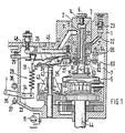
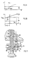
- FIG. 1 shows a simplified fuel distributor injection pump shown in longitudinal section, on the construction principle of which the invention is implemented
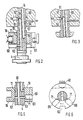
- FIG. 2 shows a partial section through a distributor force injection pump of the type according to FIG. 1 with a first embodiment of the invention
- FIG. 3 shows a modification of the embodiment shown in FIG.
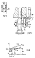
- FIG. 4 shows the handling of the tax-effective part of the pump casing and inner cylinder casing of the ring slide according to the embodiment of Figure 2 with the grooves shown there as control openings
- Figure 5 shows a third embodiment of the invention as a section through a part of the pump piston and the ring slide with an inside the outer surface 6 shows a section perpendicular to the configuration according to FIG. 5
- FIG. 7 shows the development of the tax-effective part of the pump piston jacket and of the inner cylinder
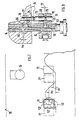
- FIG. 8 shows a fourth exemplary embodiment of the invention with a cut-off device in the form of a slide bolt that is modified compared to the above embodiments, inserted into a bore of the ring slide
- FIG. 8 shows a fourth exemplary embodiment of the invention with a cut-off device in the form of a slide bolt that is modified compared to the above embodiments, inserted into a bore of the ring slide
- FIG. 9 shows a control diagram for the exemplary embodiment according to FIG. 8 with a piston stroke curve over the angle of rotation
- FIG. 10 shows a simplified control diagram over the tax-effective routes and areas for switching off the silent running device according to FIG. 8
- FIG. 11 shows a fifth exemplary embodiment of the invention as an embodiment modified compared to FIG. 8
- FIG. 12 shows a sixth exemplary embodiment of the invention as a section through part of the ring slide in a modification 11
- FIG. 13 shows a seventh exemplary embodiment of the invention with a setting variant for the slide pin in the ring slide modified from FIG. 11
- FIG. 14 shows a control diagram for the exemplary embodiment according to FIG. 11.
- a bushing 2 is arranged in a housing 1 of a fuel injection pump shown in FIG. 1, in the bore 3 of which forms a pump cylinder 3, a pump piston 4, driven by a cam drive 5, executes a reciprocating and at the same time rotating movement.
- the pump piston encloses a pump working chamber 6 on its one end face and partially projects out of the pump cylinder 3 into a pump suction chamber 7 which forms a relief chamber and is enclosed in the housing 1.
- the pump work chamber 6 is supplied with fuel via longitudinal grooves 8 arranged in the lateral surface of the pump piston and a suction bore 9, which passes radially through the bushing 2 and runs in the housing 1 and extends from the pump suction chamber 7, as long as the pump piston assumes its suction stroke or its bottom dead center position .
- the pump suction chamber is supplied with fuel from a fuel tank via a feed pump 11.
- a pressure control valve By means of a pressure control valve, the pressure in the suction space is usually controlled as a function of the speed, in order, for example, to carry out a speed-dependent spray adjustment hydraulically via a speed-controlled pressure to be able to.
- the start of stroke of the pump piston is adjusted to early with increasing speed in a known manner.
- a longitudinal channel in the form of a blind bore leads away from the pump work chamber 6 in the pump piston and is referred to as a relief channel 14.
- a transverse bore 15 branches off, which leads to a first outlet opening 16 on the circumference of the pump piston 4, into an area in which it protrudes into the suction space 7.
- a quantity adjusting element in the form of a ring slide 18 is arranged on the pump piston, which slides tightly on the pump piston with the lateral surface 17 of its inner cylinder, is rotatable and displaceable and with a first control edge 19 formed by the lateral surface 17 and its upper end face controls first outlet opening 16.
- a radial bore 20 branches off from the relief duct 14 and leads to a distributor opening 21 on the circumference of the pump piston.
- delivery lines 22 branch off in a radial plane from the pump cylinder 3 and are arranged distributed around the circumference of the pump cylinder 3 in accordance with the number of cylinders to be supplied with fuel of the associated internal combustion engine.
- the delivery lines each lead via a valve 23, which is designed as a check valve or as a pressure relief valve in a known manner, to the fuel injection points, not shown.
- the fuel injection quantity regulator 25 provided for the adjustment of the ring slide has a tensioning lever 26 which can be pivoted about an axis 27, is designed with one arm and is coupled at its lever arm end to a control spring arrangement 28, through which it can be pivoted towards a full load stop 32.
- This consists of an idle spring 29 which is arranged between the head of a coupling member 30 and the tensioning lever, the coupling member 30 being pushed through an opening in the tensioning lever and being connected to a main control spring 31 at the other end facing away from the head.
- This is in turn suspended from its other end on a swivel arm 33 which can be adjusted with an adjusting lever 35 via a shaft 34 which is passed through the pump housing.
- the adjusting lever can be operated arbitrarily by an operator between an adjustable full load stop 36 and an adjustable idle stop 37.
- the adjusting lever 35 is connected to the accelerator pedal, which the driver of the motor vehicle, which is equipped with the internal combustion engine and the injection pump, actuates according to his torque request.
- the simple coil spring shown here as the main control spring other control spring arrangements can of course also be used, which are designed in multiple stages and / or pretensioned.
- a start lever 39 can also be pivoted about the axis 27, which is designed with two arms and is coupled with one arm via a ball head 40 in an engaging manner in a transverse groove 41 running in a radial plane to the ring slide with the ring slide.
- the other arm of the starter lever has a leaf spring 49 which, as a starter spring, is supported against the tensioning lever 26 in a spreading manner.
- Actuator 42 acts on precisely this lever arm of start lever 39 Speed sensor in the form of a centrifugal force control arrangement 43 of a known type. This is driven synchronously with the drive shaft 44 of the fuel injection pump via a gear transmission 45.
- the actuator 42 With increasing speed, the actuator 42 is moved together with the start lever 39 and the ring slide 18 against the force of the start spring 49 until the start lever comes into contact with the full load stop 32.
- the ring slide is adjusted from a highest position closest to the pump workspace according to a start quantity setting to the pump piston drive side and the excess start quantity is thereby regulated. If the start lever comes into contact with the tensioning lever, both levers are pivoted away from the full stop 32 against the force of the idle spring 29 as the speed increases until the main regulating spring 31 then comes into effect on the idle area.
- this spring is moved further when the set speed is reached and the ring slide 18 is displaced to reduce the injection quantity.
- a greater or lesser amount of fuel injection is injected at a certain speed.
- the axis 27 is mounted on an adjusting lever 46 which can be pivoted about an axis 47 which is fixed to the housing and is held in contact with an adjustable stop 48 by a spring.
- a second relief channel 51 is provided in the pump piston, which in addition to the first relief channel of a second outlet opening 52 on the jacket of the pump piston within the pump cylinder 3 to a first outlet opening 53 on the jacket of the pump piston leads in the region of the ring slide 18 which can be moved onto the pump piston.
- the second outlet opening is connected via a throttle bore 54 to the second relief channel 51 made from a blind bore.
- the second outlet opening 52 opens out in the region of an annular groove 55 provided on the wall of the pump cylinder 3, with which a second outlet opening 56 of the first relief channel 14 also comes into contact during the course of the pump piston stroke.
- This second outlet opening 56 is formed by a radial channel 57 branching off from the first relief channel 14.
- the assignment of the second outlet openings 52 and 56 to the annular groove 55 are such that the second outlet opening 52 of the second relief channel is already in the bottom dead center position of the pump piston at the beginning of its delivery stroke with the annular groove 55, but from a stroke hx through the wall of the Pump cylinder 3 is closed again.
- the second outlet opening 56 of the first relief channel comes into contact with the annular groove 55 only after a stroke sv, which is smaller than the stroke hx, with the annular groove 55.
- the pump piston conveys fuel when the first outlet opening 16 is closed by the ring slide, but this fuel only serves to compress the fuel in the pump work chamber 6 and in the subsequent connection to the respectively controlled injection nozzle. until a high pressure arises close to or equal to the opening pressure of the injection valve. A high-pressure injection can then take place after the preliminary stroke sv.
- the maximum duration of this "leakage" via the second relief channel 51 is determined by the stroke length hx-sv.
- the second outlet opening 52 is then closed and the pump piston conveys it at its design delivery rate.
- This delivery stroke is terminated when the first outlet opening 16 of the first relief channel 14 is opened by the first control edge 19 formed between the lateral surface 17 of the inner cylinder of the ring slide 18 and its end face on the pump work chamber side.
- This stroke is greater, the further the ring slide 18 is displaced towards the pump work space by the fuel injection quantity regulator.
- Grooves, such as the groove 58 are arranged distributed on the ring slide, specifically when only a first outlet opening 53 of the second relief channel is provided, in the same number and rotation angle distribution as the pump piston performs delivery strokes per revolution.
- the first outlet opening 53 is then already connected to one of the grooves 58 in the idling range. If the internal combustion engine is provided to supply an even number of cylinders of an internal combustion engine, two outlet openings 53 diametrically opposite one another can also be provided instead of one.
- the number of grooves 58 is then halved and they are then at a simple angular distance from one another, as shown, for example, in FIG. There, the distance is 90 degrees when a four-cylinder internal combustion engine is supplied.
- the quiet running device described above is also designed to be switched off.
- the ring slide 18 must be turned so far that the second outlet opening 53 of the second relief channel 51 is completely closed at the beginning of the stroke of the pump piston or at the latest after passing through the preliminary stroke sv and that it remains in the course of the subsequent pump piston delivery stroke.
- the ring slide 18 is provided with a rotating device 60 which has an angle lever 61, on the one lever arm of which a spherical head 62 is seated, which engages as a sliding part in a longitudinal groove 63 on the ring slide. As shown in FIG. 2, this longitudinal groove lies diametrically opposite the attack of the ball head 40 and extends in the longitudinal direction to the pump piston axis.
- the angle lever 61 is mounted on an axle 64 which is firmly anchored to the housing and on which the end of the other U-shaped lever arm 65 of the angle lever is also pivotably arranged.
- the other lever arm which is bent in a U-shape, is coupled to the adjusting lever 85 via a transmission device, not shown here, which contains a freewheel and can be moved synchronously with the latter.
- An adjustment of the ring slide takes place in the direction of rotation with the beginning of the pivoting-out movement of the adjusting lever 35 from its idling stop until the ring slide rotating position has reached an end position in a partial position of the adjusting lever 35.
- this movement is intercepted via the freewheel provided.
- the grooves 58 are displaced so far that the second outlet opening 53 of the second relief channel no longer comes into contact with one of these grooves and the full, original pump piston stroke is available for conveying the injection quantity.
- FIG 4 a development of the piston skirt and the outer surface 17 of the inner cylinder of the ring slide is shown.
- the position of the control opening or the cross sections of the grooves 58 as well as the first outlet opening 53 and the first outlet opening 16 are shown at an angular distance of 90 degrees from this settlement.
- the position of the control opening is also shown in broken lines if the ring slide has been rotated for the purpose of switching off.
- FIG. 3 a variant of the embodiment of Figure 2 is shown, in which a recess 67 is provided as the second outlet opening 52 of the second relief channel 51, which is connected via a throttle bore 54 'with the second relief channel 51.
- the recess preferably has boundary edges parallel to the boundary edges of the annular groove 55.
- This embodiment allows a more precise adjustment of the stroke, from which the connection between the second relief channel 51 and the first relief channel 14 is effectively interrupted.
- the throttle can also be provided at another location. For this, e.g.
- a throttle bore is provided between the first outlet opening 53 and the second relief channel 51, or the throttle is connected into the connection between the second outlet opening 56 of the first relief channel and the latter.
- the grooves 58 emanating from the pump drive side according to the exemplary embodiment according to FIG. 2, it is possible, in a modification to this according to the configuration according to FIG. 5, to design the control opening as a window-shaped opening within the lateral surface 17 of the inner cylinder of the ring slide.
- the latter has a radial channel 69, the entry of which into the lateral surface 17 of the ring slide as a rectangular window 71 with the first Control edge 19 parallel boundary edges is formed.
- This window acts in an analogous manner to the groove 58.
- the second relief channel 51 is preferably provided with two first outlet openings 53, which then only have half the control openings or windows 71 of the number that would be necessary if only a second outlet opening 53 would be provided is attributed.
- two radial channels 69 are provided symmetrically to the axis formed by the longitudinal groove 63 and the point of application of the ball head 40, each with a window 71 in a distributor injection pump, which serves to supply four internal combustion engine cylinders. This arrangement can be seen from the section in FIG. 6. Otherwise, what has been said about FIGS. 2 and 3 applies.
- throttles can also be provided here in the connection between the first outlet openings 53 and the second relief channel 51.
- FIG. 7 shows the development of the lateral surface 17 of the inner cylinder of the ring slide 18 for the exemplary embodiment according to FIG. 5 analogously to FIG.
- FIG. 4 it can be seen here that the width of the window 71 or of the groove 58 permits a variation in the spray adjustment without influencing the function of the quiet run.
- a throttle bore 72 is shown as a concentrically small circle to the outer circumference of the first outlet opening 53, which replaces the throttle bore 54, as is provided in FIG. 2.
- the silent running device is switched off here in the same way as described above.
- a fourth exemplary embodiment according to FIG. 8 the shutdown takes place in a different way.
- the ring slide which has one or more windows 71 as the control opening, which is connected to a channel 69 which radially penetrates the ring slide and opens into the suction chamber 7, the ring slide is not designed to be rotatable here. Instead, a bore 73 is provided in the ring slide, which is parallel to the axis of the inner cylinder of the ring slide 18 and fully intersects the radial channel 69.
- a slide pin 74 is arranged in a tightly displaceable manner and has a head 75 on its projecting end on the pump work chamber side, which head engages behind a coupling spring 76 and holds it in contact with an adjusting member 78.
- This is a bolt that runs parallel to the pump cylinder 3 through the pump housing and can be actuated by an adjusting device.
- This pin is essentially stationary, so that when the ring slide 18 is axially adjusted, the slide pin 74 is displaced in the bore 73.
- the slide pin 74 in the example shown has an annular groove 79 which, after a certain stroke adjustment sy of the annular slide 18, is closed out of its idle position by the wall of the bore 73.
- the radial channel 69 is also closed and fuel leakage via the second relief channel 51, as described at the beginning, is prevented.
- This also results in a load-dependent shutdown of the silent running device, the free displaceability of the slide pin 74 replacing the freewheeling necessary in the above exemplary embodiments.
- the setting possibility of the setting element 78 results in an exact setting and the possibility of changing this setting also as a function of specific operating values. These would then be parameters that have an influence on the quiet running of the internal combustion engine or are dependent on it. Since only one control opening can be realized here with reasonable effort, first outlet openings 52 are provided on the pump piston in accordance with the number of pump strokes of the pump piston per revolution.
- the pump piston stroke over the angle of rotation is shown in FIG.
- the connection between the pump working space and the first outlet opening 53 of the second relief channel 51 is established only after a preliminary stroke sv.
- the second outlet opening 52 of the second relief channel 51 which is initially closed by the wall of the pump cylinder 3 at the start of the stroke of the pump piston.
- the second outlet opening 56 of the first relief channel 14, on the other hand, is connected to the annular groove 55 from the start and is closed after a stroke hx.
- the embodiment shown here represents an equivalent embodiment to the exemplary embodiment according to FIG. 2 on this point. In FIG.
- FIG. 10 refers to the special embodiment according to FIG. 8 and the configuration of the shutdown, specifically as a diagram of the piston stroke over the load .
- the ring slide position is set with sy. at which a shutdown of the quiet running device occurs.
- the preload stroke sv is entered as a parallel to the abscissa, and the stroke hx, in which leakage is prevented via the annular groove 55, is parallel to this.
- the stroke is plotted as an oblique straight line, increasing from zero load to full load, at which opening of the first outlet opening 16 of the first relief channel basically ends the high-pressure delivery of the pump piston.
- the greatest possible stroke changes from the end of stroke at idle h FEL to the end of stroke at full load h FEV .
- the fact that the outflow cross-section decreases due to gradual closing of the radial channel 69 also results in a continuous transition from the idling range with a reduced injection rate to partial and full load ranges with the full injection rate.
- the configuration has the advantage that the switch-off device has few moving parts and is arranged securely inside that of the fuel injection pump. From the outside, only the setting element is to be adjusted for adjustment, while the load-dependent shutdown is carried out automatically by the controller.
- Figure 12 shows a variant of the embodiment of Figure 8, in which the one boundary edge of the annular groove 79 ', which determines the closing process of the radial channel 69, is conical. This allows the transition behavior to be controlled even better.
- the throttled outflow as was determined by the throttle bore 54 in the previous exemplary embodiments, can also be controlled at this point.
- An influence depending on the operating parameters is possible via the setting member 78.
- the slide pin can in principle also be provided with a transverse channel, although the rotational position of the slide pin must be secured.
- Adjustment options also result in a modified form by the embodiment according to FIG. 13, where instead of an annular groove with mutually parallel boundary edges on the slide pin 74 'an annular recess is provided, one of which has a boundary edge 81 in a radial plane to the axis of the slide pin and the other controlling second Boundary edge 82 is inclined to the radial plane.
- the slide pin 74 'on its head 75' has a toothing 84 which is offset with a corresponding toothing here offset to the axis of the slide pin 74 ' Adjusting member engages 78 ⁇ .
- the head 75 of the slide pin 74 ' is held by a coupling spring 76 in contact with the pump housing.
- An adjusting member arranged offset to the axis of the slide pin can also be used if a resilient element fastened to the pump housing is connected between adjusting member and head 74.
- the setting member can be axially displaced for setting, as in the exemplary embodiment according to FIG.
- the setting element can also be used to shut down the silent running device instead of stopping it by adjusting the ring slide by the fuel injection quantity regulator.
- FIG. 11 shows a seventh exemplary embodiment, which is designed as a development of the exemplary embodiment according to FIG. 8.
- the second relief channel 51 ' with its second outlet opening 52' in constant communication with the annular groove 55.
- the second outlet opening 56 of the first relief channel 14 is in communication with the annular groove 55 at the beginning of the pump piston stroke, but is then after passing through one Hubes of size hx closed.
- the forward stroke sv provided in the exemplary embodiment according to FIG. 8, via which the pump piston delivers at full delivery rate for preloading the volume on the high-pressure side, is realized here elsewhere.
- This embodiment variant is controlled as follows: after an initial stroke sx, the first outlet opening 53 comes into connection with the annular groove 85. From this point, fuel can flow out as a leakage flow via a throttle 54 'upstream of the first outlet opening 53, as long as the pump piston stroke is less than hx or the delivery end of the pump piston h FE , at which the first relief opening 16 is opened by the control edge 19 of the ring slide, has not been reached.
- the quiet running device is switched off by the adjustment of the ring slide 18 to a higher load, in that the one limiting edge of the annular groove 79 closes the radial channel 69 '.
Landscapes
- Engineering & Computer Science (AREA)
- Chemical & Material Sciences (AREA)
- Combustion & Propulsion (AREA)
- Mechanical Engineering (AREA)
- General Engineering & Computer Science (AREA)
- Fuel-Injection Apparatus (AREA)
Abstract
Description
Die Erfindung geht von einer Kraftstoffeinspritzpumpe nach der Gattung des Hauptanspruchs aus. Bei einer durch die DE-OS 3203582 bekannten Kraftstoffeinspritzpumpe wird die erste Austrittsöffnung des ersten Entlastungskanals durch eine als Steueröffnung dienende Innenringnut am Innenzylinder des Ringschiebers gesteuert, wobei die Innenringnut ständig über einen Kanal mit dem Entlastungsraum verbunden ist. Die erste Austrittsöffnung des zweiten Entlastungskanals wird fener durch von der pumpenarbeitsraumseitigen Stirnfläche des Ringschiebers ausgehende Nuten gesteuert, die derart und in solcher Zahl angeordnet sind, daß bei jedem zweiten Pumpenkolbenförderhub eine der Nuten in Hubrichtung der ersten Austrittsöffnung des zweiten Entlastungskanals liegt. Dies führt aber nur dann zu einer Entlastung des Arbeitsraumes über den ersten Entlastungskanal, die Ringnut und den zweiten Entlastungskanal so lange eine Verbindung zwischen dem ersten und dem zweiten Entlastungskanal hergestellt ist und die erste Austrittsöffnung zugleich in eine der Nuten mündet. Dies ist bei der bekannten Kraftstoffeinspritzpumpe in der Leerlaufstellung des Ringschiebers der Fall. Wird der Ringschieber in Richtung höherer Last verschoben, so ist die zweite Austrittsöffnung des zweiten Entlastungskanals schon verschlossen bevor die erste Austrittsöffnung geöffnet wird. Man erhält dadurch bei der bekannten Kraftstoffeinspritzpumpe ein lastabhängiges Abschalten der Einspritzung bei einem Teil der Förderhübe des Pumpenkolbens. Auf diese Weise wird eine Zylinderteilabschaltung der Brennkraftmaschine bei Niedriglastbetrieb erzielt und der Verbrauch der Brennkraftmaschine dadurch optimiert, daß die nicht abgeschalteten Zylinder mit relativ höherer Last und damit höherem Wirkungsgrad betrieben werden.The invention is based on a fuel injection pump according to the preamble of the main claim. In a fuel injection pump known from DE-OS 3203582, the first outlet opening of the first relief channel is controlled by an inner annular groove serving as a control opening on the inner cylinder of the ring slide, the inner annular groove being constantly connected to the relief chamber via a channel. The first outlet opening of the second relief channel is also controlled by grooves extending from the end face of the ring slide on the pump work chamber side, which are arranged and in such a number that each second pump piston delivery stroke has one of the grooves in the stroke direction of the first outlet opening of the second relief channel. However, this only relieves the work space via the first relief channel, the annular groove and the second relief channel as long as a connection is established between the first and the second relief channel and the first outlet opening simultaneously opens into one of the grooves. This is the case with the known fuel injection pump in the idle position of the ring slide. If the ring slide in the direction of higher load moved, the second outlet opening of the second relief channel is closed before the first outlet opening is opened. In the known fuel injection pump, this results in a load-dependent shutdown of the injection in part of the delivery strokes of the pump piston. In this way, a partial cylinder deactivation of the internal combustion engine is achieved in low-load operation and the consumption of the internal combustion engine is optimized in that the cylinders that are not deactivated are operated with a relatively higher load and thus higher efficiency.
Durch die DE-OS 3218275 ist andererseits eine Kraftstoffeinspritzpumpe mit einer Leiselaufeinrichtung bekannt, bei der vom Pumpenarbeitsraum nur eine Entlastungsleitung abführt, deren einzige Austrittsöffnung am Pumpenkolbenumfang innerhalb des Entlastungsraumes ebenfalls durch einen Ringschieber gesteuert wird. Dieser weist ausgehend von seiner Stirnfläche ebenfalls Nuten auf, die aber einen schlitzförmigen, drosselnden Querschnitt zur Innenzylindermantelfläche des Ringschiebers haben. Über diese wird beim Förderhub des Pumpenkolbens und einer entsprechenden Drehstellung des Ringschiebers zuerst die Verbindung zwischen Austrittsöffnung und Entlastungsraum hergestellt und dann erst über die von Innenbohrung und Stirnfläche des Ringschiebers gebildete Steuerkante. Damit wird im Bypass zur zu den Einspritzdüsen geförderten Kraftstoffeinspritzmenge eine Teilmenge als Leckmenge von der Gesamtförderrate des Pumpenkolbens abgezweigt, was über eine somit reduzierte Einspritzrate einen leisen Lauf der Brennkraftmaschine ermöglicht. Durch eine Verdreheinrichtung, die ohne Rücksicht auf die Verstellung des Ringschiebers durch einen Kraftstoffeinspritzmengenregler arbeitet, läßt sich die Wirksamkeit der drosselnden Nuten bzw. die Leiselaufeinrichtung abschalten.From DE-OS 3218275, on the other hand, a fuel injection pump with a quiet running device is known, in which only one discharge line leads away from the pump work chamber, the only outlet opening on the circumference of the pump piston within the relief chamber is also controlled by a ring slide. Starting from its end face, this also has grooves, which, however, have a slit-shaped, throttling cross section to the inner cylinder surface of the ring slide. During the delivery stroke of the pump piston and a corresponding rotary position of the ring slide, this is used first to establish the connection between the outlet opening and the relief space and only then via the control edge formed by the inner bore and end face of the ring slide. In this way, in the bypass to the fuel injection quantity delivered to the injection nozzles, a partial quantity is branched off as a leak quantity from the total delivery rate of the pump piston, which enables the internal combustion engine to run quietly via a reduced injection rate. The effectiveness of the throttling grooves or the quiet running device can be switched off by means of a turning device which works regardless of the adjustment of the ring slide by a fuel injection quantity regulator.
Bei dieser bekannten Kraftstoffeinspritzpumpe ergeben sich jedoch Probleme bezüglich der Steuerung der über die Drosselquerschnitte abströmenden Kraftstoffmenge. Insbesondere bestehen Probleme, die Kraftstoffmenge vom Übergang aus dem Leerlaufbereich in den Teillastbereich kontinuierlich zu erhöhen, damit kein Lastsprung beim Lataufnahme auftritt. Weiterhin ergeben sich Probleme, wenn der Kraftstoffeinspritzpumpe eine Spritzbeginnverstelleinrichtung zugeordnet wird, die regelmäßig darin besteht, daß die erste Austrittsöffnung gegenüber der Antriebswellendrehstellung der Kraftstoffeinspritzpumpe verstellt wird.In this known fuel injection pump, however, problems arise with regard to the control of the amount of fuel flowing out through the throttle cross sections. In particular, there are problems that To continuously increase the amount of fuel from the transition from the idling range to the partial load range so that there is no sudden jump in load when recording lat. Furthermore, problems arise when the fuel injection pump is assigned an injection start adjustment device which regularly consists in the first outlet opening being adjusted relative to the rotational position of the drive shaft of the fuel injection pump.
Durch die DE-A-3510221 ist schließlich eine Kraftstoffeinspritzpumpe der gattungsgemäßen Art bekannt. Dort ist jedoch als Steuerorgan ein temperaturabhängiges Schieberventil vorgesehen, das in dem lastabhängig verschiebbaren Ringschieber angeordnet ist und temperaturabhängig arbeitet derart, daß es bei betriebswarmer Brennkraftmaschine eine als Drosselbohrung ausgebildete Verbindung zwischen der ersten Austrittsöffnung des zweiten Entlastungskanals und dem Entlastungsraum verschließt. Diese Einrichtung hat die Aufgabe, daß bei kalter, bzw. noch nicht betriebswarmer Brennkraftmaschine ein Teil der vom Pumpenkolben geförderten Kraftstoffmenge über die Drossel abströmen kann, um somit die Einspritzrate in diesem Betriebsbereich zu verringern und zugleich die Dauer der Einspritzung zu verlängen. Bei betriebswarmer Brennkraftmaschine wird dagegen diese Entlastung verhindert.Finally, a fuel injection pump of the generic type is known from DE-A-3510221. There, however, a temperature-dependent slide valve is provided as a control element, which is arranged in the load-dependent displaceable ring slide and operates in a temperature-dependent manner in such a way that, when the internal combustion engine is warm, it closes a connection designed as a throttle bore between the first outlet opening of the second relief channel and the relief chamber. This device has the task that when the internal combustion engine is cold or not yet warm, part of the fuel quantity delivered by the pump piston can flow out via the throttle, in order to reduce the injection rate in this operating range and at the same time to extend the duration of the injection. However, this relief is prevented when the internal combustion engine is at operating temperature.
Die erfindungsgemäße Kraftstoffeinspritzpumpe mit den kennzeichnenden Merkmalen des Hauptanspruchs hat demgegenüber den Vorteil, daß eine Leiselaufeinrichtung verwirklichbar ist, bei der über einen festgelegten Teilhub, der zusätzlich lastabhängig modifizierbar ist, ein Lecken bzw. eine Einspritzung mit reduzierte Einspritzrate erfolgt, wobei die Leiselaufeinrichtug unabhängig davon vorzugsweise in Abhängigkeit von Betriebsparametern der Brennkraftmaschine ruckfrei abgeschaltet werden kann. Bei Vollastbetrieb steht so die volle Förderleistung der Kraftstoffeinspritzpumpe zur Verfügung. Die Abschaltung kann vorzugsweise auch in Abhängigkeit von der Last mit ruckfreiem Übergang erfolgen. Diese Funktion wird dabei in keiner Weise von einer Spritzbeginnverstelleinrichtung beeinflußt, da die Steueröffnungen breit genug sind, um den ganzen Spritzbeginnverstellbereich zu decken.The fuel injection pump according to the invention with the characterizing features of the main claim has the advantage that a quiet running device can be implemented, in which a fixed partial stroke, which can also be modified depending on the load, leads to leakage or an injection with a reduced injection rate, the quiet running device preferably being independent of this can be switched off smoothly depending on the operating parameters of the internal combustion engine. At full load, the full delivery rate of the fuel injection pump is available. The switch-off can preferably also take place as a function of the load with a smooth transition. This function is in no way influenced by a spray start adjustment device, since the control openings are wide enough to cover the entire spray start adjustment range.
Durch die in den Unteransprüchen aufgeführten Maßnahmen sind vorteilhafte Weiterbildungen und Verbesserungen der im Hauptanspruch angegebenen Kraftstoffeinspritzpumpe möglich. Durch die Ausgestaltung von Anspruch 2 ergibt sich der Vorteil, daß immer ein konstanter Vorspannhub des Pumpenkolbens vor Beginn der Förderwirksamkeit des Pumpenkolbens und vor Leckbeginn zur Verfügung steht, so daß Schwankungen der Kraftstoffeinspritzmenge aufgrund des Totvolumeneinflusses weitgehend vermieden werden. Durch die Verstelleinrichtung gemäß Anspruch 6 erhält man eine sichere Abschaltung der Leiselaufeinrichtung, wobei bei der Ausgestaltung gemäß Anspruch 7 noch hinzukommt, daß in einfacher weise die Abschaltung lastabhängig über die Ringschieberhubbewegung erfolgt ohne daß ein zusätzlicher Hebel notwendig wird und daß eine zusätzliche Einflußnahme auf den Bereich der wirksamkeit der Leiselaufeinrichtung, d.h. des Leckens über den Drosselquerschnitt durch das Einstellglied erfolgen kann.The measures listed in the subclaims permit advantageous developments and improvements of the fuel injection pump specified in the main claim. The embodiment of
Sieben Ausführungsbeispiele der Erfindung sind in der Zeichnung dargestellt und werden in der nachfolgenden Beschreibung näher erläutert. Es zeigen Figur 1 eine vereinfachte im Längsschnitt wiedergegebene Kraftstoffverteilereinspritzpumpe, an deren Konstruktionsprinzip die Erfindung verwirklicht wird, Figur 2 einen Teilschnitt durch eine Verteilerkrafteinspritzpumpe der Bauart gemäß Figur 1 mit einem ersten Ausführungsbeispiel der Erfindung, Figur 3 eine Modifikation der in Figur 2 wiedergegebenen Ausführung als drittes Ausführungsbeispiel, Figur 4 die Abwicklung des steuerwirksamen Teils von Pumpenmantel und Innenzylindermantel des Ringschiebers gemaß Ausführungsbeispiel nach Figur 2 mit den dort wiedergegebenen Nuten als Steueröffnungen, Figur 5 ein drittes Ausführungsbeispiel der Erfindung als Schnitt durch ein Teil des Pumpenkolbens und des Ringschiebers mit einer innerhalb der Mantelfläche des Innenzylinders des Ringschiebers liegenden Steueröffnung, Figur 6 einen Schnitt senkrecht zur Ausgestaltung nach Figur 5, Figur 7 die Abwicklung des steuerwirksamen Teils des Pumpenkolbenmantels und des Innenzylindermantels des Ringschiebers zum Ausführungsbeispiel nach Figur 5, Figur 8 ein viertes Ausführungsbeispiel der Erfindung mit einer gegenüber den vorstehenden Ausführungsformen abgewandelten Abschalteinrichtung in Form eines Schieberbolzens eingesetzt in eine Bohrung des Ringschiebers, Figur 9 ein Steuerdiagramm zum Ausführungsbeispiel nach Figur 8 mit einer Kolbenhubkurve über den Drehwinkel, Figur 10 ein vereinfachtes Steuerdiagramm über die steuerwirksamen Strecken und Bereiche der Abschaltung der erfindungsgemäßen Leiselaufeinrichtung gemäß Figur 8, Figur 11 ein fünftes Ausführungsbeispiel der Erfindung als gegenüber Figur 8 modifizierte Ausführungsform, Figur 12 ein sechstes Ausfuhrungsbeispiel der Erfindung als Schnitt durch ein Teil des Ringschiebers in Abwandlung zur Ausführung nach Figur 11, Figur 13 ein siebtes Ausführungsbeispiel der Erfindung mit einer gegenüber Figur 11 abgewandelten Einstellausführung für den Schieberbolzen im Ringschieber und Figur 14 ein Steuerdiagramm zum Ausführungsbeispiel nach Figur 11.Seven exemplary embodiments of the invention are shown in the drawing and are explained in more detail in the description below. 1 shows a simplified fuel distributor injection pump shown in longitudinal section, on the construction principle of which the invention is implemented, FIG. 2 shows a partial section through a distributor force injection pump of the type according to FIG. 1 with a first embodiment of the invention, FIG. 3 shows a modification of the embodiment shown in FIG. 2 as the third Embodiment, Figure 4 shows the handling of the tax-effective part of the pump casing and inner cylinder casing of the ring slide according to the embodiment of Figure 2 with the grooves shown there as control openings, Figure 5 shows a third embodiment of the invention as a section through a part of the pump piston and the ring slide with an inside the
In einem Gehäuse 1 einer in Figur 1 wiedergegebenen Kraftstoffeinspritzpumpe ist eine Buchse 2 angeordnet, in deren einen Pumpenzylinder 3 bildenden Bohrung 3 ein Pumpenkolben 4 durch einen Nockenantrieb 5 angetrieben eine hin- und hergehende und zugleich rotierende Bewegung ausführt. Der Pumpenkolben schließt auf seiner einen Stirnseite einen Pumpenarbeitsraum 6 ein und ragt zum Teil aus der Pumpenzylinder 3 heraus in einen einen Entlastungsraum bildenden Pumpensaugraum 7, der im Gehäuse 1 eingeschlossen ist.A
Der Pumpenarbeitsraum 6 wird über in der Mantelfläche des Pumpenkolbens angeordnete Längsnuten 8 und eine radial durch die Buchse 2 hindurchtretende und im Gehäuse 1 verlaufende Saugbohrung 9, die vom Pumpensaugraum 7 ausgeht, mit Kraftstoff versorgt, solange der Pumpenkolben seinen Saughub bzw. seine untere Totpunktlage einnimmt. Der Pumpensaugraum wird über eine Förderpumpe 11 aus einem Kraftstoffbehälter mit Kraftstoff versorgt. Durch ein Drucksteuerventil wird dabei der Druck üblicherweise im Saugraum drehzahlabhängig gesteuert, um somit z.B. hydraulisch über einen drehzahlabhängig gesteuerten Druck eine drehzahlabhängige Spritzverstellung vornehmen zu können. Dabei wird in bekannter Weise der Hubbeginn des Pumpenkolbens mit steigender Drehzahl auf Früh verstellt.The
Vom Pumpenarbeitsraum 6 führt im Pumpenkolben ein Längskanal in Form einer Sackbohrung ab und wird als Entlastungskanal 14 bezeichnet. Von diesem zweigt eine Querbohrung 15 ab, die zu einer ersten Austrittsöffnung 16 am Umfang des Pumpenkolbens 4 führt, in einen Bereich, in dem dieser in den Saugraum 7 ragt. In diesem Bereich ist auf dem Pumpenkolben ein Mengenverstellorgan in Form eines Ringschiebers 18 angeordnet, der mit der Mantelfläche 17 seines Innenzylinders dicht auf dem Pumpenkolben gleitet, verdreh- und verschiebbar ist und mit einer durch die Mantelfläche 17 und seine obere Stirnseite gebildete erste Steuerkante 19 die erste Austrittsöffnung 16 steuert.A longitudinal channel in the form of a blind bore leads away from the
Vom Entlastungskanal 14, zweigt ferner eine Radialbohrung 20 ab, die zu einer Verteileröffnung 21 am Pumpenkolbenumfang führt. Im Arbeitsbereich dieser Verteileröffnung zweigen in einer radialenEbene vom Pumpenzylinder 3 Förderleitungen 22 ab, die entsprechend der Zahl der mit Kraftstoff zu versorgenden Zylinder der zugehörigen Brennkraftmaschine am Umfang des Pumpenzylinders 3 verteilt angeordnet sind. Die Förderleitungen führen über je ein Ventil 23, das als Rückschlagventil oder als Druckentlastungsventil in bekannter Weise ausgestaltet ist, zu den nicht gezeigten Kraftstoffeinspritzstellen. Zu diesen wird, sobald bei Beginn des Förderhubs des Pumpenkolbens nach einer entsprechenden Verdrehung desselben die Saugbohrung 9 durch die Mantelfläche des Pumpenkolbens verschlossen ist, der im Pumpenarbeitsraum 6 befindliche Kraftstoff über den Entlastungskanal 14, die Radialbohrung 20 und die Verteilernut 21 gefördert. Diese Förderung wird dann unterbrochen, wenn im Laufe des Pumpenkolbenhubs die erste Austrittsöffnung 16 durch den Ringschieber geöffnet wird und in Verbindung mit dem Saugraum 7 kommt. Ab diesem Punkt wird der vom Pumpenkolben verdrängte restliche Kraftstoff nur noch in den Saugraum gefördert. Je höher der Ringschieber 18 zum Pumpenarbeitsraum hin verstellt ist, desto größer ist die vom Pumpenkolben geförderte Kraftstoffeinspritzmenge.A radial bore 20 branches off from the
Der für die Verstellung des Ringschiebers vorgesehene Kraftstoffeinspritzmengenregler 25 weist einen Spannhebel 26 auf, der um eine Achse 27 schwenkbar, einarmig ausgebildet ist und an seinem Hebelarmende mit einer Regelfederanordnung 28 gekoppelt ist, durch die er zu einem Vollastanschlag 32 hin schwenkbar ist. Diese besteht aus einer Leerlauffeder 29, die zwischen dem Kopf eines Kupplungsgliedes 30 und dem Spannhebel angeordnet ist, wobei das Kupplungsglied 30 durch eine Öffnung im Spannhebel durchgesteckt ist und am anderen vom Kopf abgewandten Ende mit einer Hauptregelfeder 31 verbunden ist. Diese ist wiederum an ihrem anderen Ende an einem Schwenkarm 33 eingehängt, der über eine durch das Pumpengehäuse durchgeführte Welle 34 mit einem Verstellhebel 35 verstellbar ist. Der Verstellhebel ist dabei zwischen einem einstellbaren Vollastanschlag 36 und einem einstellbaren Leerlaufanschlag 37 willkürlich von einer Bedienungsperson betätigbar. Zum Beispiel wird der Verstellhebel 35 mit dem Gaspedal verbunden, das der Fahrer des Kraftfahrzeuges, das mit der Brennkraftmaschine und der Einspritzpumpe ausgerüstet ist, entsprechend seinem Drehmomentwunsch betätigt. Statt der hier gezeigten einfachen Schraubenfeder als Hauptregelfeder können natürlich auch andere Regelfederanordnungen verwendet werden, die mehrstufig und/oder vorgespannt ausgeführt sind.The fuel
Um die Achse 27 ist ferner ein Starthebel 39 schwenkbar, der zweiarmig ausgeführt ist und mit einem Arm über einen Kugelkopf 40 in eine in einer Radialebene zum Ringschieber verlaufende Quernut 41 eingreifend mit dem Ringschieber gekoppelt ist. Der andere Arm des Starthebels weist eine Blattfeder 49 auf, die sich als Startfeder gegen die Spannhebel 26 spreizend an diesem abstützt. Auf eben diesen Hebelarm des Starthebels 39 wirkt das Stellglied 42 eines Drehzahlgebers in Form einer Fliehkraftstellanordnung 43 bekannter Bauart. Diese wird synchron zur Antriebswelle 44 der Kraftstoffeinspritzpumpe über ein Zahnradgetriebe 45 angetrieben. Mit zunehmender Drehzahl werden also nach dem Start das Stellglied 42 zusammen mit dem Starthebel 39 und dem Ringschieber 18 entgegen der Kraft der Startfeder 49 verschoben, bis der Starthebel am Vollastanschlag 32 anliegenden Spannhebel 26 zur Anlage kommt. Im Laufe dieser Bewegung wird der Ringschieber von einer höchsten, pumpenarbeitsraumnächsten Stellung entsprechend einer Startmengeneinstellung zur Pumpenkolbenantriebsseite hin verstellt und dabei die Startübermenge abgeregelt. Kommt der Starthebel zur Anlage an den Spannhebel, so werden beide Hebel bei steigender Drehzahl entgegen der Kraft der Leerlauffeder 29 vom Vollstanschlag 32 weggeschwenkt, bis dann anschließend an den Leerlaufbereich die Hauptregelfeder 31 zur Wirkung kommt. Je nach Ausgestaltung dieser Feder als All-Drehzahlreglerfeder oder als Leerlaufenddrehzahlreglerfeder wird der Spannhebel bei Erreichen der eingestellten Drehzahl weiter bewegt und der Ringschieber 18 zur Reduzierung der Einspritzmenge verschoben. Je nach Stellung des Verstellhebels 35 wird also bei einer bestimmten Drehzahl eine größere oder geringere Kraftstoffeinspritzmenge eingespritzt.A
Zur Einstellung ist die Achse 27 auf einem Einstellhebel 46 gelagert, der um eine gehäusefeste Achse 47 schwenkbar ist und durch eine Feder in Anlage an einem einstellbaren Anschlag 48 gehalten wird.For adjustment, the
Soweit bisher beschrieben entspricht die Kraftstoffeinspritzpumpe einer bekannten Ausgestaltung. In Figur 2 ist nun die erfindungsgemäße Weiterbildung für ein erstes Ausführungsbeispiel der Erfindung dargestellt, die aus folgendem besteht: Außer dem Entlastungskanal 14, der im folgenden als erster Entlastungskanal bezeichnet wird, ist im Pumpenkolben ein zweiter Entlastungskanal 51 vorgesehen, der neben dem ersten Entlastungskanal von einer zweiten Austrittsöffnung 52 am Mantel des Pumpenkolbens innerhalb des Pumpenzylinders 3 zu einer ersten Austrittsöffnung 53 am Mantel des Pumpenkolbens führt im Bereich des auf den Pumpenkolben verschiebbaren Ringschiebers 18. Die zweite Austrittsöffnung ist über eine Drosselbohrung 54, mit dem aus einer Sackbohrung hergestellten zweiten Entlastungskanal 51 verbunden. Die zweite Austrittsöffnung 52 mündet im Bereich einer an der Wand des Pumpenzylinders 3 vorgesehenen Ringnut 55, mit der auch eine zweite Austrittsöffnung 56 des ersten Entlastungskanals 14 im Laufe des Pumpenkolbenhubs in Verbindung kommt. Diese zweite Austrittsöffnung 56 wird durch einen vom ersten Entlastungskanal 14 abzweigenden radialen Kanal 57 gebildet. Die Zuordnung der zweiten Austrittsöffnungen 52 und 56 zur Ringnut 55 sind derart, daß die zweite Austrittsöffnung 52 des zweiten Entlastungskanals bereits in der unteren Totpunktstellung des Pumpenkolbens bei Beginn seines Förderhubes mit der Ringnut 55 in Verbindung steht, ab einem Hub hx aber durch die Wand des Pumpenzylinders 3 wieder verschlossen wird. Die zweite Austrittsöffnung 56 des ersten Entlastungskanals kommt mit der Ringnut 55 erst nach einem Hub sv, der kleiner ist als der Hub hx, mit der Ringnut 55 in Verbindung. Über diesen Hub wird vom Pumpenkolben bei durch den Ringschieber verschlossener erster Austrittsöffnung 16 Kraftstoff gefördert, der aber nur der Verdichtung des Kraftstoffes im Pumpenarbeitsraum 6 und in der anschließenden Verbindung zur jeweils angesteuerten Einspritzdüse dient. bis ein Hochdruck nahe oder gleich dem Öffnungsdruck des Einspritzventils entsteht. Nach dem Vorhub sv kann dann eine Hochdruckeinspritzung erfolgen.So far, the fuel injection pump corresponds to a known embodiment. In Figure 2, the inventive development for a first embodiment of the invention is shown, which consists of the following: In addition to the
Nach Herstellung der Verbindung der zweiten Austrittsöffnung 56 mit der Ringnut 55 kann aber Kraftstoff über die Ringnut 55, die zweite Austrittsöffnung 52 den zweiten Entlastungskanal 51 und dessen erste Austrittsöffnung 53 abströmen, soweit letztere geöffnet ist. In der in Figur 2 gezeigten Stellung des Ringschiebers mündet diese in eine am Ringschieber vorgesehene Steueröffnung in Form einer Nut 58, die ausgehend von der pumpenantriebsseitigen Stirnseite des Ringschiebers in diesen eingearbeitet ist. In diesem Falle kann Kraftstoff gedrosselt über die Drosselbohrung 54 parallel zur Förderung in die jeweilige Druckleitung 22 abströmen, was die einspritzwirksame Förderrate des Pumpenkolbens mindert. Durch Dimensionierung der Drossel kann dabei eine gewünschte Förderrate erzielt werden, die einen leisen Verbrennungsablauf in den Zylindern der Brennkraftmaschine bewirkt. Die maximale Dauer dieses "Leckens" über den zweiten Entlastungskanal 51 wird durch die Hublänge hx-sv bestimmt. Danach wird die zweite Austrittsöffnung 52 verschlossen und es fördert der Pumpenkolben mit seiner konstruktiv gegebenen Förderrate. Dieser Förderhub wird dann beendet, wenn die erste Austrittsöffnung 16 des ersten Entlastungskanals 14 durch die zwischen Mantelfläche 17 des Innenzylinders des Ringschiebers 18 und dessen pumpenarbeitsraumseitiger Stirnseite gebildete erste Steuerkante 19 geöffnet wird. Dieser Hub ist umso größer, je weiter der Ringschieber 18 zum Pumpenarbeitsraum hin durch den Kraftstoffeinspritzmengenregler verschoben ist. Nuten, wie die die Nut 58, sind am Ringschieber verteilt angeordnet, und zwar dann, wenn nur eine erste Austrittsöffnung 53 des zweiten Entlastungskanals vorgesehen ist, in gleicher Anzahl und Drehwinkelverteilung wie der Pumpenkolben Förderhübe pro Umdrehung ausführt. Bei Hubbeginn des Pumpenkolbens steht dann im Leerlaufbereich die erste Austrittsöffnung 53 bereits mit einer der Nuten 58 in Verbindung. Wird die Brennkraftmaschine zur Versorgung einer geraden Anzahl von Zylindern einer Brennkraftmaschine vorgesehen, so können statt einer auch zwei einander diametral gegenüberliegende Austrittsöffnungen 53 vorgesehen werden. Die Zahl der Nuten 58 halbiert sich dann und sie liegen dann in einfachem Drehwinkelabstand voneinander, wie z.B. in Figur 6 gezeigt. Dort beträgt der Abstand 90 Grad bei Versorgung einer Vierzylinderbrennkraftmaschine.After the connection of the second outlet opening 56 to the
Die oben beschriebene Leiselaufeinrichtung ist ferner abschaltbar ausgeführt. Dazu muß der Ringschieber 18 so weit verdreht werden, daß die zweite Austrittsöffnung 53 des zweiten Entlastungskanals 51 bei Hubbeginn des Pumpenkolbens bzw. spätestens nach Durchlaufen des Vorhubes sv vollständig geschlossen ist und es auch im Laufe des anschließenden Pumpenkolbenförderhubes bleibt. Zu diesem Zweck ist der Ringschieber 18 mit einer Verdreheinrichtung 60 versehen, die einen Winkelhebel 61 aufweist, an dessen einem Hebelarm ein Kugelkopf 62 sitzt, der als Gleitteil in eine Längsnut 63 am Ringschieber eingreift. Diese Längsnut liegt z.B. wie in Figur 2 gezeigt diametral dem Angriff des Kugelkopfs 40 gegenüber und verläuft in Längsrichtung zur Pumpenkolbenachse. Der Winkelhebel 61 ist auf einer gehäusefestverankerten Achse 64 gelagert, auf der ebenfalls das Ende des anderen, U-förmig gebogenen Hebelarms 65 des Winkelhebels schwenkbar angeordnet ist. Der U-förmig gebogene andere Hebelarm ist über eine hier nicht dargestellte, einen Freilauf enthaltene Übertragungseinrichtung mit dem Verstellhebel 85 gekoppelt und kann synchron zu diesem bewegt werden. Dabei erfolgt eine Verstellung des Ringschiebers in Drehrichtung mit Beginn der Ausschwenkbewegung des Verstellhebels 35 von seinem Leerlaufanschlag bis in einer Teilstellung des Verstellhebels 35 die Ringschieberdrehstellung eine Endstellung erreicht hat. Bei Weiterbewegung des Verstellhebels wird diese Bewegung über den vorgesehene Freilauf abgefangen. In der verdrehten Stellung des Ringschiebers 18 werden die Nuten 58 so weit versetzt, daß die zweite Austrittsöffnung 53 des zweiten Entlastungkanals nicht mehr in Verbindung mit einer dieser Nuten kommt und der volle, ursprüngliche Pumpenkolbenhub zur Förderung von Einspritzmenge zur Verfügung steht.The quiet running device described above is also designed to be switched off. For this purpose, the
In Figur 4 ist eine Abwicklung des Kolbenmantels und der Mantelfläche 17 des Innenzylinders des Ringschiebers dargestellt. Dieser Abwicklung sind die Stellungen der Steueröffnung bzw. der Querschnitte der Nuten 58 sowie der ersten Austrittsöffnung 53 und der ersten Austrittsöffnung 16 im 90 Grad Drehwinkelabstand wiedergegeben. Ferner ist eine Pumpenkolbenerhebungskurve, entlang der sich die erste Austrittsöffnung 53 des zweiten Entlastungskanals 51 in bezug auf die Steueröffnung 58 bewegt. Es ist ferner gestrichelt die Position der Steueröffnung eingetragen, wenn der Ringschieber zwecks Abschalten verdreht wurde.In Figure 4, a development of the piston skirt and the
In Figur 3 ist eine Variante zum Ausführungsbeispiel nach Figur 2 gezeigt, bei der als zweite Austrittsöffnung 52 des zweiten Entlastungskanals 51 eine Ausnehmung 67 vorgesehen ist, die über eine Drosselbohrung 54′ mit dem zweiten Entlastungskanal 51 verbunden ist. Die Ausnehmung hat vorzugsweise zu den Begrenzungskanten der Ringnut 55 parallele Begrenzungskanten. Diese Ausführung erlaubt eine exaktere Einstellung des Hubes, ab dem wirksam die Verbindung zwischen zweitem Entlastungskanal 51 und erstem Entlastungskanal 14 unterbrochen wird. Statt der Anordnung der Drossel an der in Figuren 2 und 3 vorgesehenen Stelle zwischen zweiter Austrittsöffnung 52 und deren Verbindung zum zweiten Entlastungskanal 51 kann die Drossel auch an anderer Stelle vorgesehen werden. Dazu kann z.B. eine Drosselbohrung zwischen erster Austrittsöffnung 53 und zweitem Entlastungskanal 51 vorgesehen werden oder die Drossel in die Verbindung zwischer zweiter Austrittsöffnung 56 des ersten Entlastungskanals und diesem geschaltet werden. Die in Figur 2 und 3 gezeigten Lösungen und die letztgenannte Lösung haben den Vorteil, daß das Volumen des Hochdruckteils stromaufwärts der Drossel geringer ist und somit auch das schädliche Totvolumen.In Figure 3, a variant of the embodiment of Figure 2 is shown, in which a
Statt der von der Pumpenantriebsseite ausgehenden Nuten 58 gemäß Ausführungsbeispiel nach Figur 2 ist es in Abwandlung dazu gemäß Ausgestaltung nach Figur 5 möglich, die Steueröffnung als fensterförmige Öffnung innerhalb der Mantelfläche 17 des Innenzylinders des Ringschiebers auszubilden. Bei dem in Figur 5 wiedergegebenen Schnitt durch ein Teil des Pumpenkolbens und den Ringschieber weist dieser einen Radialkanal 69 auf, dessen Eintritt in die Mantelfläche 17 des Ringschiebers als rechteckförmiges Fenster 71 mit zur ersten Steuerkante 19 parallelen Begrenzungskanten ausgebildet ist. Dieses Fenster wirkt in analoger Weise zur Nut 58. Vorzugsweise wird auch hier der zweite Entlastungskanal 51 mit zwei ersten Austrittsöffnungen 53 versehen, denen dann nur noch die Hälfte an Steueröffnungen bzw. Fenstern 71 der Zahl, die notwendig wäre, wenn nur eine zweite Austrittsöffnung 53 vorgesehen wäre, zugerechnet ist. Somit werden symmetrisch zu der durch die Längsnut 63 und den Angriffspunkt des Kugelkopfes 40 gebildeten Achse zwei Radialkanäle 69 mit je einem Fenster 71 bei einer Verteilereinspritzpumpe vorgesehen, die zur Versorgung von vier Brennkraftmaschinenzylindern dient. Diese Anordnung ist dem Schnitt aus Figur 6 zu entnehmen. Im übrigen gilt das zu Figuren 2 und 3 Gesagte. Insbesonder können auch hier Drosseln in der Verbindung zwischen den ersten Austrittsöffnungen 53 zum zweiten Entlastungskanal 51 vorgesehen werden.Instead of the
Figur 7 zeigt für das Ausführungsbeispiel nach Figur 5 analog zu Figur 4 die Abwicklung der Mantelfläche 17 des Innenzylinders des Ringschiebers 18. Auch hier ist eine Pumpenkolbenerhebungskurve gezeigt, der die erste Austrittsöffnung 53 des zweiten Entlastungskanals 51 folgt. Es sind verschiedene Positionen der ersten Austrittsöffnung 53′ dargestellt und zugleich auch die Abschaltposition des Ringschiebers mit dem Fenster 71′. Wie auch bei Figur 4 ist hier erkennbar, daß die Breite des Fensters 71 bzw. der Nut 58 eine Variation der Spritzverstellung zuläßt, ohne die Funktion des Leiselaufes zu beeinflussen. In dem Diagramm ist als konzentrisch kleiner Kreis zum Außenumfang der ersten Austrittsöffnung 53 eine Drosselbohrung 72 gezeigt, die die Drosselbohrung 54, wie sie in Figur 2 vorgesehen ist, ersetzt. Die Abschaltung der Leiselaufeinrichtung erfolgt hier in gleicher Weise wie im Vorstehenden beschrieben.FIG. 7 shows the development of the
Bei einem vierten Ausführungsbeispiel gemäß Figur 8 erfolgt nun jedoch die Abschaltung auf eine andere Art und Weise. Ausgehend von dem Ausführungsbeispiel nach Figur 5, das als Steueröffnung ein bzw. mehrere Fenster 71 aufweist, die mit einem Kanal 69 verbunden ist, der radial den Ringschieber durchdringt und in den Saugraum 7 mündet, ist hier der Ringschieber jedoch nicht verdrehbar ausgestaltet. Stattdessen ist im Ringschieber eine Bohrung 73 vorgesehen, die parallel zur Achse des Innenzylinders des Ringschiebers 18 liegt und den Radialkanal 69 voll schneidet. In dieser Bohrung ist dicht verschiebbar ein Schieberbolzen 74 angeordnet, der zur Pumpenarbeitsraumseite an seinem herausragenden Ende einen Kopf 75 aufweist, den eine Koppelfeder 76 hintergreift und in Anlage an ein Einstellglied 78 hält. Dieses ist ein parallel zum Pumpenzylinder 3 durch das Pumpengehäuse geführter Bolzen, der durch eine Einstelleinrichtung betätigbar ist. Dieser Bolzen steht im wesentlichen fest eingestellt still, so daß bei einer Axialverstellung des Ringschiebers 18 der Schieberbolzen 74 in der Bohrung 73 verschoben wird. Zur Steuerung des Durchtritts des Radialkanals 69 weist der Schieberbolzen 74 im ausgeführten Beispiel eine Ringnut 79, die nach einer bestimmten Hubverstellung sy des Ringschiebers 18 aus seiner Leerlaufstellung heraus durch die Wand der Bohrung 73 verschlossen wird. Entsprechend wird auch der Radialkanal 69 geschlossen und ein Lecken von Kraftstoff über den zweiten Entlastungskanal 51, wie eingangs beschrieben, verhindert. Es ergibt sich hier also ebenfalls eine lastabhängige Abschaltung der Leiselaufeinrichtung, wobei die freie Verschiebbarkeit des Schieberbolzens 74 den in vorstehenden Ausführungsbeispielen notwendigen Freilauf ersetzt. Darüber hinaus ergibt sich über die Einstellmöglichkeit des Einstellgliedes 78 eine exakte Einstellung und die Möglichkeit dieser Einstellung auch in Abhängigkeit von bestimmten Betriebswerten zu verändern. Dies wären dann Parameter, die insbesondere Einfluß auf den leisen Lauf der Brennkraftmaschine nehmen bzw. davon abhängig sind. Da sich hier mit vertretbarem Aufwand nur eine Steueröffnung verwirklichen läßt, sind am Pumpenkolben entsprechend der Zahl der Pumpenübe des Pumpenkolbens pro Umdrehung erste Austrittsöffnungen 52 vorgesehen.In a fourth exemplary embodiment according to FIG. 8, however, the shutdown takes place in a different way. Starting from In the exemplary embodiment according to FIG. 5, which has one or
Zur Funktion des Ausführungsbeispiels nach Figur 8 ist in Figur 9 der Pumpenkolbenhub über den Drehwinkel dargestellt. Wie bei den vorstehenden Ausführungsbeispielen wird erst nach einem Vorhub sv die Verbindung zwischen Pumpenarbeitsraum und erster Austrittsöffnung 53 des zweiten Entlastungskanals 51 hergestellt. In diesem Falle ist es die zweite Austrittsöffnung 52 des zweiten Entlastungskanals 51, die zunächst durch die Wand des Pumpenzylinders 3 bei Hubbeginn des Pumpenkolbens verschlossen ist. Die zweite Austrittsöffnung 56 des ersten Entlastungskanals 14 dagegen steht bereits von Anfang an mit der Ringnut 55 in Verbindung und wird nach einem Hub hx verschlossen. Die hier gezeigte Ausführung stellt eine äquivalente Ausführung zum Ausführungsbeispiel nach Figur 2 in diesem Punkte dar. In Figur 9 ist nun der Gesamthub des Pumpenkolbens hx eingetragen, über den der Pumpenarbeitsraum Verbindung zur Ringnut 55 hat. Die Differenz zwischen den Hüben hx und sv stellt die Strecke des Leckens bzw. der verminderten Kraftstoffeinspritzrate hl dar. Das Diagramm in Figur 10 nimmt Bezug auf die spezielle Ausführung nach Figur 8 und der Ausgestaltung der Abschaltung, und zwar als Diagramm des Kolbenhubs über der Last. In diesem Diagramm ist mit sy die Ringschieberstellung eingestellt. bei der eine Abschaltung der Leiselaufeinrichtung auftritt. Weiterhin ist als Parallele zur Abszisse der Vorspannhub sv eingetragen und parallel dazu der Hub hx, bei der über die Ringnut 55 ein Lecken unterbunden wird. Ferner ist als schräge Gerade, von Nullast bis Vollast ansteigend der Hub aufgetragen, bei dem durch Öffnen der ersten Austrittsöffnung 16 des ersten Entlastungskanals die Hochdruckförderung des Pumpenkolbens grundsätzlich beendet wird. Je nach Stellung des Ringschiebers verändert sich dabei der größtmögliche Hub von dem Förderendehub bei Leerlauf hFEL bis zum Förderendehub bei Vollast hFEV. Man erkennt aus diesem Diagramm, daß mit zunehmender Last auch bei Lecken ausgehend von dem Leerlaufbereich eine Zunahme der Einspritzmenge erfolgt über eine Restförderung mit voller Förderrate im Anschluß an die Förderung hl mit verminderter Förderrate. Auf diese Weise ist optimal eine Lastaufnahme gegeben. Dadurch daß ferner der Abströmquerschnitt durch allmähliches Verschließen des Radialkanals 69 abnimmt, ergibt sich auch hier ein kontinuierlicher Übergang aus dem Leerlaufbereich mit reduzierter Einspritzrate zu Teil- und Vollastbereichen mit voller Einspritzrate. Die Ausgestaltung hat den Vorteil, daß die Abschalteinrichtung wenig bewegte Teile aufweist und gesichert im innern der der Kraftstoffeinspritzpumpe angeordnet ist. Von außen ist zur Einstellung nur das Einstellglied zu verstellen, während die lastabhängige Abschaltung automatisch durch den Regler erfolgt.For the function of the exemplary embodiment according to FIG. 8, the pump piston stroke over the angle of rotation is shown in FIG. As in the above exemplary embodiments, the connection between the pump working space and the first outlet opening 53 of the
Figur 12 zeigt eine Variante zum Ausführungsbeispiel nach Figur 8, bei der die eine Begrenzungskante der Ringnut 79′, die den Schließvorgang des radialen Kanals 69 bestimmt, kegelförmig ausgebildet ist. Hiermit kann das Übergangsverhalten noch besser gesteuert werden. Auch das gedrosselte Abströmen, wie das in den vorhergehenden Auführungsbeispielen durch die Drosselbohrung 54 bestimmt war, kann an dieser Stelle gesteuert werden. Eine Einflußnahme in Abhängigkeit von Betriebsparametern ist dabei über das Einstellglied 78 möglich. Statt der Ringnut kann der Schieberbolzen grundsätzlich auch mit einem Querkanal versehen werden, wobei allerdings die Drehstellung des Schieberbolzens gesichert werden muß.Figure 12 shows a variant of the embodiment of Figure 8, in which the one boundary edge of the annular groove 79 ', which determines the closing process of the
Einstellmöglichkeiten ergeben sich ferner in abgewandelter Form durch das Ausführungsbeispiel nach Figur 13, wo statt einer Ringnut mit einander parallelen Begrenzungskanten am Schieberbolzen 74′ eine ringförmige Ausnehmung vorgesehen ist, dessen eine Begrenzungskante 81 in einer radialen Ebene zur Achse des Schieberbolzens liegt und dessen andere steuernde zweite Begrenzungskante 82 zur Radialebene geneigt ist. Weiterhin weist der Schieberbolzen 74′ an seinem Kopf 75′ eine Verzahnung 84 auf, die mit einer entsprechenden Verzahnung eines hier zur Achse des Schieberbolzens 74′ versetzt gelagerten Einstellglieds 78˝ eingreift. Durch Drehen dieses Einstellglieds 78˝ wird der Schieberbolzen 74 verdreht und der Ringschieberhub, bei dem der Radialkanal 69 verschlossen wird, verändert. Der Kopf 75 des Schieberbolzens 74′ wird durch eine Koppelfeder 76 in Anlage am Pumpengehäuse gehalten. Ein zur Achse des Schieberbolzens versetzt angeordnetes Einstellglied kann auch dann verwendet werden, wenn zwischen Einstellglied und Kopf 74 ein am Pumpengehäuse befestigtes federndes Element geschaltet ist. Das Einstellglied kann in diesem Fall wie beim Ausführungsbeispiel nach Figur 11 zur Einstellung axial verschoben werden. Grundsätzlich kann mit Hilfe des Einstellglieds bei entsprechender Betätigungssteuerung auch ein Abstellen der Leiselaufeinrichtung anstelle einer Abstellung durch die Verstellung des Ringschiebers durch den Kraftstoffeinspritzmengenregler erfolgen.Adjustment options also result in a modified form by the embodiment according to FIG. 13, where instead of an annular groove with mutually parallel boundary edges on the slide pin 74 'an annular recess is provided, one of which has a boundary edge 81 in a radial plane to the axis of the slide pin and the other controlling
Mit Figur 11 ist schließlich ein siebtes Ausführungsbeispiel dargestellt, das als Weiterbildung des Ausführungsbeispiels nach Figur 8 ausgeführt ist. Bei diesem Ausführungsbeispiel ist der zweite Entlastungskanal 51′ mit seiner zweiten Austrittsöffnung 52′ in ständiger Verbindung mit der Ringnut 55. Die zweite Austrittsöffnung 56 des ersten Entlastungskanals 14 hingegen ist bei Beginn des Pumpenkolbenhubs mit der Ringnut 55 in Verbindung, wird dann aber nach Durchlaufen eines Hubes der Größe hx verschlossen. Der beim Ausführungsbeispiel nach Figur 8 vorgesehene Vorhub sv, über den der Pumpenkolben mit voller Förderrate zum Vorspannen des hochdruckseitigen Volumens fördert, ist hier an anderer Stelle verwirklicht. Statt wie beim Ausführungsbeispiel nach Figuren 2, 5 oder 8, wo mit Hubbeginn die erste Austrittsöffnung 53 des zweiten Entlastungskanals bereits mit der Steueröffnung 58 bzw. 71 verbunden war, ist hier die erste Austrittsöffnung 53′ des zweiten Entlastungskanals bei Hubbeginn zunächst durch die Mantelfläche 17 des Ringschiebers 18 verschlossen. Als Steueröffnung ist ferner eine Ringnut 85 vorgesehen, die in die Mantelfläche 17 des Ringschiebers eingearbeitet ist und die über einen Radialkanal 69′ entsprechend dem Radialkanal 69 von Figur 8 mit dem Saugraum 7 bzw. dem Entlastungsraum verbunden ist. Der Durchtritt des Radialkanals 69′ wird in gleicher Weise wie bei den Ausführungsbeispielen nach Figur 8, 12 oder 13 durch einen Schieberbolzen 74 gesteuert. der z.B. eine Ringnut 79 aufweist.Finally, FIG. 11 shows a seventh exemplary embodiment, which is designed as a development of the exemplary embodiment according to FIG. 8. In this embodiment, the second relief channel 51 'with its second outlet opening 52' in constant communication with the
Die Steuerung dieser Ausführungsvariante erfolgt folgendermaßen: Nach einem anfänglichen Hub sx kommt die erste Austrittsöffnung 53 in Verbindung mit der Ringnut 85. Ab diesem Punkt kann Kraftstoff über eine der ersten Austrittsöffnung 53 vorgeschaltete Drossel 54′ als Leckstrom abfließen, so lange der Pumpenkolbenhub kleiner ist als hx oder das Förderende des Pumpenkolbens hFE, bei dem die erste Entlastungsöffnung 16 durch die Steuerkante 19 des Ringschiebers aufgesteuert wird, nicht erreicht ist. Wie beim Ausführungsbeispiel nach Figur 8 wird durch die Verstellung des Ringschiebers 18 zu höherer Last die Leiselaufeinrichtung abgeschaltet, indem die eine Begrenzungskante der Ringnut 79 den Radialkanal 69′ verschließt. Dies erfolgt nach einem Ringschieberhub sy, wie er dem Diagramm Figur 14 entnehmbar ist. Mit der Verstellung des Ringschiebers 18 zu höherer Last ändert sich aber zugleich auch die Strecke sx, nach der die erste Austrittsöffnung 53 in Verbindung mit der Ringnut 85 kommt. Auf diese Weise wird bei Lastaufnahme im Anschluß an den für die Vorspannung des Kraftstoffvolumens auf der Hochdruckseite benötigten Hub sv noch ein Hub mit voller Förderrate vorgeschaltet, bis dann ein Lecken über den Hub hl eintreten kann. Da ferner die sich daran anschließende Leckstrecke hl durch den Hub hx begrenzt ist, nimmt somit mit zunehmender Last die Leckstrecke ab. Nach Verschließen der zweiten Austrittsöffnung 56 kann dann bei entsprechender Last noch ein kleiner Hub des Pumpenkolbens mit wiederum voller Förderrate sich anschließen bis das geometrische Förderende hFE durch Aufsteuern der ersten Entlastungsöffnung 16 des ersten Entlastungskanals erreicht wird. Das Lecken bei Lastaufnahme wird dabei grundsätzlich durch die Verstellung des Ringschiebers über dessen Verstellbereich sy gesteuert. Dabei läßt sich ein sanfter Übergang auch durch Androsselung des Radialkanals 69′ erzielen.This embodiment variant is controlled as follows: after an initial stroke sx, the first outlet opening 53 comes into connection with the
Mit dieser Einrichtung wird eine abgeänderte Folge von Einspritzraten während des Leiselaufs erzielt, die in besonderen Fällen wünschenswert ist. Vorteilhaft für einen weichen Lauf ist es, wenn bei Lastaufnahme aus dem Leerlauf zunächst nur eine kleine Kraftstoffmenge mit voller Einspritzrate und Durchdringfähigkeit im Brennraum eingespritzt wird, der dann über einen Teilwinkel der Einspritzphase eine Einspritzung mit verminderter Einspritzrate folgt, die dem Zündverzug Rechnung trägt. Zur Leistungssteigerung bei Lastaufnahme kann dann nach dem Zündverzug mit voller Einspritzrate grundsätzlich eingespritzt werden. In Figur 14 ist mit hl die Leckstrecke bezeichnet, die zwischen den achsparallelen Linien hx und der ansteigenden Linien der Hübe sx liegt.With this device, a modified sequence of injection rates during the quiet run is achieved, which is desirable in special cases. It is advantageous for a smooth run if only a small amount of fuel with full injection rate and penetrability is initially injected into the combustion chamber when the load is taken up from idling, which then follows an injection with a reduced injection rate over a partial angle of the injection phase, which takes the ignition delay into account. In order to increase the power when the load is taken up, it is generally possible to inject at full injection rate after the ignition delay. In Figure 14, hl denotes the leakage distance which lies between the axially parallel lines hx and the rising lines of the strokes sx.
Claims (16)
Applications Claiming Priority (2)
| Application Number | Priority Date | Filing Date | Title |
|---|---|---|---|
| DE3644583 | 1986-12-27 | ||
| DE19863644583 DE3644583A1 (en) | 1986-12-27 | 1986-12-27 | FUEL INJECTION PUMP FOR INTERNAL COMBUSTION ENGINES |
Publications (2)
| Publication Number | Publication Date |
|---|---|
| EP0341243A1 EP0341243A1 (en) | 1989-11-15 |
| EP0341243B1 true EP0341243B1 (en) | 1991-09-25 |
Family
ID=6317301
Family Applications (1)
| Application Number | Title | Priority Date | Filing Date |
|---|---|---|---|
| EP19870907745 Expired - Lifetime EP0341243B1 (en) | 1986-12-27 | 1987-12-04 | Fuel injection pumps for internal combustion engines |
Country Status (6)
| Country | Link |
|---|---|
| US (1) | US4924833A (en) |
| EP (1) | EP0341243B1 (en) |
| JP (1) | JPH01501807A (en) |
| KR (1) | KR890700193A (en) |
| DE (2) | DE3644583A1 (en) |
| WO (1) | WO1988005128A1 (en) |
Families Citing this family (5)
| Publication number | Priority date | Publication date | Assignee | Title |
|---|---|---|---|---|
| JPH0494426A (en) * | 1990-08-08 | 1992-03-26 | Zexel Corp | Load timer for distribution type fuel injection pump |
| DE4100093A1 (en) * | 1991-01-04 | 1992-07-09 | Bosch Gmbh Robert | FUEL INJECTION PUMP FOR INTERNAL COMBUSTION ENGINES WITH LOAD AND / OR SPEED-RELATED INJECTION HISTORY |
| DE4106813A1 (en) * | 1991-03-04 | 1992-09-10 | Bosch Gmbh Robert | FUEL INJECTION PUMP FOR INTERNAL COMBUSTION ENGINES |
| DE4436416A1 (en) * | 1994-10-12 | 1996-04-18 | Bosch Gmbh Robert | Fuel injection pump |
| DE19713868A1 (en) * | 1997-04-04 | 1998-10-08 | Bosch Gmbh Robert | Fuel injection pump for internal combustion engines |
Family Cites Families (12)
| Publication number | Priority date | Publication date | Assignee | Title |
|---|---|---|---|---|
| DE2142704C3 (en) * | 1971-08-26 | 1974-04-25 | Robert Bosch Gmbh, 7000 Stuttgart | Fuel injection pump for multi-cylinder internal combustion engines |
| JPS6045307B2 (en) * | 1978-01-30 | 1985-10-08 | 株式会社ボッシュオートモーティブ システム | distribution type fuel injection pump |
| DE3203582A1 (en) * | 1982-02-03 | 1983-08-11 | Robert Bosch Gmbh, 7000 Stuttgart | Fuel injection pump for internal combustion engines |
| DE3326973A1 (en) * | 1983-07-27 | 1985-02-07 | Robert Bosch Gmbh, 7000 Stuttgart | FUEL INJECTION PUMP FOR INTERNAL COMBUSTION ENGINES |
| DE3424883A1 (en) * | 1984-07-06 | 1986-02-06 | Robert Bosch Gmbh, 7000 Stuttgart | FUEL INJECTION PUMP FOR INTERNAL COMBUSTION ENGINES |
| DE3524387A1 (en) * | 1984-07-10 | 1986-01-23 | Nissan Motor Co., Ltd., Yokohama, Kanagawa | Fuel injection pump |
| DE3429128A1 (en) * | 1984-08-08 | 1986-02-20 | Robert Bosch Gmbh, 7000 Stuttgart | Fuel injection pump for internal combustion engines |
| DE3436042A1 (en) * | 1984-10-02 | 1986-04-03 | Robert Bosch Gmbh, 7000 Stuttgart | FUEL INJECTION PUMP FOR SELF-IGNITIONING INTERNAL COMBUSTION ENGINES |
| DE3510221A1 (en) * | 1985-03-21 | 1986-09-25 | Robert Bosch Gmbh, 7000 Stuttgart | Fuel injection pump for internal combustion engines |
| DE3524241A1 (en) * | 1985-07-06 | 1987-01-08 | Bosch Gmbh Robert | FUEL INJECTION PUMP FOR INTERNAL COMBUSTION ENGINES |
| DE3612068A1 (en) * | 1986-04-10 | 1987-10-15 | Bosch Gmbh Robert | FUEL INJECTION PUMP FOR INTERNAL COMBUSTION ENGINES WITH EXHAUST GAS RECIRCULATION |
| DE3644147A1 (en) * | 1986-12-23 | 1988-07-07 | Bosch Gmbh Robert | FUEL INJECTION PUMP FOR INTERNAL COMBUSTION ENGINES |
-
1986
- 1986-12-27 DE DE19863644583 patent/DE3644583A1/en not_active Withdrawn
-
1987
- 1987-12-04 WO PCT/DE1987/000570 patent/WO1988005128A1/en not_active Ceased
- 1987-12-04 EP EP19870907745 patent/EP0341243B1/en not_active Expired - Lifetime
- 1987-12-04 US US07/243,300 patent/US4924833A/en not_active Expired - Fee Related
- 1987-12-04 JP JP63500022A patent/JPH01501807A/en active Pending
- 1987-12-04 DE DE8787907745T patent/DE3773397D1/en not_active Expired - Lifetime
-
1988
- 1988-08-22 KR KR1019880701022A patent/KR890700193A/en not_active Withdrawn
Also Published As
| Publication number | Publication date |
|---|---|
| WO1988005128A1 (en) | 1988-07-14 |
| KR890700193A (en) | 1989-03-10 |
| US4924833A (en) | 1990-05-15 |
| JPH01501807A (en) | 1989-06-22 |
| DE3773397D1 (en) | 1991-10-31 |
| DE3644583A1 (en) | 1988-07-07 |
| EP0341243A1 (en) | 1989-11-15 |
Similar Documents
| Publication | Publication Date | Title |
|---|---|---|
| DE4004610A1 (en) | FUEL INJECTION SYSTEM, IN PARTICULAR PUMP JET, FOR COMBUSTION MACHINES | |
| DE1258187B (en) | Fuel injection pump for internal combustion engines | |
| DE3144277C2 (en) | Fuel injection pump for internal combustion engines | |
| DE3617732C2 (en) | ||
| DE3416392C2 (en) | ||
| EP0166995B1 (en) | Fuel injection pump for internal-combustion engines | |
| EP0273225B1 (en) | Fuel injection pump for internal-combustion engines | |
| DE2355347A1 (en) | FUEL INJECTION PUMP FOR COMBUSTION MACHINES | |
| EP0341243B1 (en) | Fuel injection pumps for internal combustion engines | |
| DE4441506A1 (en) | Fuel injection pump | |
| DE4310457A1 (en) | Fuel injection pump for internal combustion engines | |
| EP0168586B1 (en) | Fuel injection pump | |
| DE3644148A1 (en) | FUEL INJECTION PUMP FOR INTERNAL COMBUSTION ENGINES | |
| DE3121108C2 (en) | ||
| EP1504188A1 (en) | Pressure valve comprising an additional jet adjusting function | |
| DE3612700C2 (en) | ||
| DE3524241A1 (en) | FUEL INJECTION PUMP FOR INTERNAL COMBUSTION ENGINES | |
| EP0502315A1 (en) | Fuel injection pump for internal combustion engines | |
| DE2644698C2 (en) | Fuel injection pump for an internal combustion engine | |
| DE2362526A1 (en) | FUEL INJECTION PUMP FOR COMBUSTION MACHINERY | |
| EP0318714B1 (en) | Exhaust gas recirculation device for internal combustion engines | |
| DE1920417C3 (en) | Fuel distributor injection pump for an internal combustion engine | |
| DE3424989C2 (en) | Fuel injection pump for internal combustion engines | |
| DE2448693C2 (en) | Speed controller for a distributor injection pump | |
| EP0461211B1 (en) | Fuel injection pump |
Legal Events
| Date | Code | Title | Description |
|---|---|---|---|
| PUAI | Public reference made under article 153(3) epc to a published international application that has entered the european phase |
Free format text: ORIGINAL CODE: 0009012 |
|
| 17P | Request for examination filed |
Effective date: 19880716 |
|
| AK | Designated contracting states |
Kind code of ref document: A1 Designated state(s): DE FR GB |
|
| 17Q | First examination report despatched |
Effective date: 19900323 |
|
| GRAA | (expected) grant |
Free format text: ORIGINAL CODE: 0009210 |
|
| AK | Designated contracting states |
Kind code of ref document: B1 Designated state(s): DE FR GB |
|
| ET | Fr: translation filed | ||
| REF | Corresponds to: |
Ref document number: 3773397 Country of ref document: DE Date of ref document: 19911031 |
|
| GBT | Gb: translation of ep patent filed (gb section 77(6)(a)/1977) | ||
| PGFP | Annual fee paid to national office [announced via postgrant information from national office to epo] |
Ref country code: GB Payment date: 19911122 Year of fee payment: 5 |
|
| PGFP | Annual fee paid to national office [announced via postgrant information from national office to epo] |
Ref country code: FR Payment date: 19911231 Year of fee payment: 5 |
|
| RAP4 | Party data changed (patent owner data changed or rights of a patent transferred) |
Owner name: ROBERT BOSCH GMBH |
|
| PGFP | Annual fee paid to national office [announced via postgrant information from national office to epo] |
Ref country code: DE Payment date: 19920228 Year of fee payment: 5 |
|
| PLBE | No opposition filed within time limit |
Free format text: ORIGINAL CODE: 0009261 |
|
| STAA | Information on the status of an ep patent application or granted ep patent |
Free format text: STATUS: NO OPPOSITION FILED WITHIN TIME LIMIT |
|
| 26N | No opposition filed | ||
| PG25 | Lapsed in a contracting state [announced via postgrant information from national office to epo] |
Ref country code: GB Effective date: 19921204 |
|
| GBPC | Gb: european patent ceased through non-payment of renewal fee |
Effective date: 19921204 |
|
| PG25 | Lapsed in a contracting state [announced via postgrant information from national office to epo] |
Ref country code: FR Effective date: 19930831 |
|
| PG25 | Lapsed in a contracting state [announced via postgrant information from national office to epo] |
Ref country code: DE Effective date: 19930901 |
|
| REG | Reference to a national code |
Ref country code: FR Ref legal event code: ST |