EP0341042A2 - Naht für Filze - Google Patents
Naht für Filze Download PDFInfo
- Publication number
- EP0341042A2 EP0341042A2 EP89304446A EP89304446A EP0341042A2 EP 0341042 A2 EP0341042 A2 EP 0341042A2 EP 89304446 A EP89304446 A EP 89304446A EP 89304446 A EP89304446 A EP 89304446A EP 0341042 A2 EP0341042 A2 EP 0341042A2
- Authority
- EP
- European Patent Office
- Prior art keywords
- machine direction
- fabric
- loops
- yarns
- cross machine
- Prior art date
- Legal status (The legal status is an assumption and is not a legal conclusion. Google has not performed a legal analysis and makes no representation as to the accuracy of the status listed.)
- Withdrawn
Links
Images


Classifications
-
- D—TEXTILES; PAPER
- D21—PAPER-MAKING; PRODUCTION OF CELLULOSE
- D21F—PAPER-MAKING MACHINES; METHODS OF PRODUCING PAPER THEREON
- D21F1/00—Wet end of machines for making continuous webs of paper
- D21F1/0027—Screen-cloths
- D21F1/0054—Seams thereof
-
- D—TEXTILES; PAPER
- D21—PAPER-MAKING; PRODUCTION OF CELLULOSE
- D21F—PAPER-MAKING MACHINES; METHODS OF PRODUCING PAPER THEREON
- D21F7/00—Other details of machines for making continuous webs of paper
- D21F7/08—Felts
- D21F7/10—Seams thereof
-
- Y—GENERAL TAGGING OF NEW TECHNOLOGICAL DEVELOPMENTS; GENERAL TAGGING OF CROSS-SECTIONAL TECHNOLOGIES SPANNING OVER SEVERAL SECTIONS OF THE IPC; TECHNICAL SUBJECTS COVERED BY FORMER USPC CROSS-REFERENCE ART COLLECTIONS [XRACs] AND DIGESTS
- Y10—TECHNICAL SUBJECTS COVERED BY FORMER USPC
- Y10S—TECHNICAL SUBJECTS COVERED BY FORMER USPC CROSS-REFERENCE ART COLLECTIONS [XRACs] AND DIGESTS
- Y10S162/00—Paper making and fiber liberation
- Y10S162/904—Paper making and fiber liberation with specified seam structure of papermaking belt
Definitions
- This invention relates generally to a joint construction for a papermakers fabric. More particularly, the invention relates to pintle seamed joints for papermakers wet press felts.
- wet felts convey the sheet of paper, paperboard, etc., from the wire or cylindrical mold through various water removing equipment.
- Such wet felts are often woven endless and are applied as such to the rolls of the papermaking machine.
- the installation of endless wet felts in the past has required cessation of operations for extended periods of time with the resultant loss of production from the paper machine.
- the present invention teaches the use of stuffer yarns in an extended fabric weave loop adjacent the seam area. Although this is occasionally contrary to the theory of continuing the same weave through the seam fabric area, the invention permits greater control over the seam configuration and in fact results in a more uniform fabric geometry at the seam.
- U.S. Patent 2,883,734 provided a wet felt of a woven open-ended strip construction which was made endless by joining together the extensions of yarn from the weave of the felt at the joining ends thereof.
- One end of the wet felt is fed through the dryer section of the machine, until it completes a full loop.
- the yarn extensions at the joining ends of the felt are continuous with the weave system thereof and are used for joining together the two ends of the felt, and a textile yarn or cord is used to secure both sets of yarn extensions together and retain the two ends of the felt connected together to form an endless belt structure.
- the wet felt is installed without having to disassemble the machine.
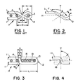
- Figure 1 is a portion of a prior art seam construction in a woven fabric which includes a plurality of machine direction yarns 1 interwoven with a plurality of cross machine direction yarns 4 .
- a plurality of integral contiguous seaming loops 2 are formed at each terminal end of the woven fabric.
- the seaming loops 2 are formed using techniques known in the art.
- loops from each end of the fabric are intermeshed to form a channel and a pintle, such as 3 , is inserted to retain the fabric ends together in a substantially continuous, endless structure.
- the machine direction yarn 1 is looped, reversed and passed in a mirror image weave with the end cross machine direction yarn 4 . This may be done during weaving, which is preferable, or in a subsequent operation.
- the machine direction yarn 1 then forms a crossover 5 and a loop 2 .
- the center to center distance between the last cross machine direction yarn 4 and the pintle channel or eye of loop 2 is designed D .
- the distance X indicates the overall free length of the loop 2 from the center of the crossover 5 .
- the distance C is the length of the crossover portion between yarn 4 and the pintle 3 in the eye of loop 2 .
- the distance E is the length of the contact between the forward and rearward sections of the yarn forming the crossover 5 .
- the prior art seam construction is deficient in that the distance D is such that the length C of the crossover portion is substantially elongated beyond the length E and a surface void or gap G is created in the respective paper carrying and machine side surface planes of the felt.
- the void or gap G tends to leave markings on the sheet, even after a batt is secured to the fabric.
- the prior art attempts to reduce the size of G have not been altogether successful.
- Figure 2 is a partial view of the forward section of the machine direction yarn 1 from Figure 1 .
- the solid plane F indicates a plane along the longitudinal axis of the forward section of the yarn forming crossover 5 .
- the broken plane R indicates a plane along the longitudinal axis of the rearward section of the yarn forming crossover 5 and is a mirror image of the forward section.
- the plane H indicates the horizontal plane of the woven fabric through the center of the eye of loop 2 .
- the plane V indicates the vertical plane perpendicular to plane H .
- the obtuse angle ⁇ is directly related to the distances C and D . The greater these lengths differ, the more the angle ⁇ will exceed 90°.
- the acute angle ⁇ is likewise related to the distance C and D . As those lengths increase ⁇ is further decreased from 90°.
- a machine direction yarn 11 extends over the end cross machine direction yarn 14 , is formed into a loop of the length L and weaves back into the fabric in a mirror image. This produces crossover 18 and the loop 12 .
- the loop length L is at least three times the average diameter of the cross machine direction yarns plus the projected pintle diameter and the machine direction yarn diameter. As illustrated L is four times the average diameter plus the pintle and the machine direction yarn diameter. Accordingly, an elongated aperture 19 is created between the free end of the loop 12 and the contiguous fixed end thereof at crossover 18. Aperture 19 always has a length of at least three times the average diameter of the cross machine direction yarn.
- a number of stuffers 16 are inserted in the aperture or channel 19 between the pintle 13 and the crossover 12 .
- the remaining space in between the stuffers and the pintle accommodates the corresponding loop from the opposite end of the fabric.
- the addition of the stuffers 16 alters the loop geometry, at the crossover 18 , to almost 90° and physically maintains that position.
- the more stuffers that can be inserted the easier it becomes to form the optimum 90° angle. That is, the angles ⁇ and ⁇ come closer together and will more nearly approximate 90°.
- the distances C and E approach each other and the difference is ideally zero. Note that in the invention the distance E is measured to the first stuffer 16 which occupies the position of the pintle in the pricr art construction. This is contrary to the prior art seam loop construction, where increasing the length of the loop increased the difference between the angle. It will be understood that as the length L increases, the amount of stuffers increases to create the required geometry. As can be seen by comparing Figures 1 and 3 , the size of the geometrical void G is considerably smaller in the invention ( Figure 3 ) than the prior art ( Figure 1 ).
- Figure 4 is a partial view of the machine direction yarn 11 in Figure 3 and is comparable to Figure 2 .
- the angle ⁇ indicates the angle from the plane H to the vertical plane V of the machine direction yarn at the crossover 18 . To get the best results the angle ⁇ should approximate 90°. With an approximately 90° angle, the dimension of the geometrical void in the surface of the seam construction will be minimized. This is indicated by the rearward portion of crossover 18 which is shown in phantom. Note that the crossover portions are nearly vertical and aligned with each other.
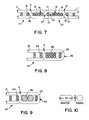
- Figure 5 shows the seam construction of Figure 3 with a batt 20 thereon.
- the batt can be needled into the stuffers 16 in the same manner as with the cross machine direction yarns 4 . This enables the batt to be strongly anchored to the seam.
- the stuffers provide control over differences in the permeability and density between the seam area and the woven fabric.
- Figure 6 shows a partial surface view of the opposing terminal ends 17 and 17′ of the endless fabric belt, without a batt, being interconnected via the pintle 13 .
- Figure 7 is a cross section of Figure 6 which more clearly shows the minimum geometrical voids G and G′ and the final seam construction.
- Figure 8 is a side view of a seam construction in accordance with an alternate embodiment of the invention. This embodiment shows that the invention is equally applicable to multi-layered fabrics.
- multi-layered fabrics plural layers of cross machine direction yarns 34 are used to interweave with machine direction yarns 31 .
- a corresponding increase in stuffer material 36 is used. This creates the same loop geometry 32 that is obtained in the preferred embodiment.
- Multiple pintles 33 may be used.
- Figure 9 is a side view of another seam construction in accordance with an alternate embodiment of the invention.
- This embodiment also pertains to the use of multi-layered fabrics.
- multi-layered fabrics use plural layers of cross machine direction yarns 44 interwoven with machine direction yarns 41 . Accordingly, for every increase in cross machine direction yarns a corresponding increase of stuffer material is used.
- this construction illustrates the use of a single layer of stuffer material 46 that equal the required stuffer area. Multiple pintles 43 may still be used.
- the fabric may be flat woven and the seaming loops formed through known loop forming techniques or back weaving.
- the fabric may be woven endless or circular and that the loops be formed in the loom as part of the weaving process.
- These weaving techniques will be known to those skilled in the art.
- a looping wire or similar device is used to form the actual loop and to simulate the pintle location during weaving.
- the stuffers will be placed within the loop aperture during weaving in the usual manner of applying stuffers to the woven fabric. During weaving, the stuffers are merely laid in the weave as it progresses on the loom without interweaving. Similarly, the stuffers may be inserted in a previously woven fabric during loop formation or back weaving.
- machine direction yarns of the fabric are woven as the cross machine direction yarns in an endless loom. Accordingly, the terms machine direction and cross machine direction will apply to the fabric on the papermaking machine and do not refer to its loom position.
- the batt 20 can be applied to the woven fabric through needling or the application of adhesives.
- needling it will generally stabilize the location of the stuffers through intermingling of fibers.
- adhesives are utilized but do not penetrate to the level of the stuffers, it is preferred to fix the stuffer by other means.
- the stuffers may be retained relative to each other and the fabric by an adhesive.
- the stuffers may be retained by application of a suitable material at the selvages of the fabric.
- papermakers fabric are subjected to heat setting and further processing which assist in stabilizing the fabric. The actual stabilizing method is subject to design considerations and will be known to those skilled in the art.
- the yarns employed in the present invention it is preferred to utilize continuous monofilament yarns. However, it is recognized that multi-filament yarns and cotton count yarns may be utilized. With respect to the stuffer yarns, it will be recognized that the stuffers may be of the same material as the remainder of the fabric or may be selected for certain characteristics. Those skilled in the art will recognize that stuffer yarns are often spun yarns or cotton count yarns which are selected to achieve certain characteristics of permeability and density in the seam area.
- the present description has referred to circular yarns which may be generally described by their diameter or axis, see Figure 3 .
- shaped yarns as shown in Figure 10 , compare with circular yarns and may be utilized in the present invention.
- the cross machine direction yarns are generally flat and rectangular as depicted in Figure 10 .
- the horizontal axis yarn 52 will be treated as the longitudinal or horizontal component of the yarn for determining the length of the loop and the required aperture.
- the vertical axis 50 will correspond generally to yarn diameter in a circular yarn and will determine the height of the stuffer.
- a one to one correlation between the stuffers and the cross machine direction yarns is not required. Accordingly, one or more circular stuffers having a diameter which conforms to the vertical axis of the shaped monofilament may be combined to produce the total horizontal length required in the aperture.
- the desired elongated loop may be initially formed by placing the machine direction yarns under tension.
- the stuffers may be utilized to preserve the weave structure and to prevent loop crushing.
- utilization of stuffers enables a loop structure having a gauge or caliper which is substantially identical to that of the fabric. Utilization of a smaller diameter pintle wire will reduce loop caliper.
- the elongated loop will not have the same rotational tendencies of the prior art loop, the stuffers help to maintain fabric caliper throughout the length of the elongated loop.
- stuffers which have an average diameter which is less than that of the cross machine direction yarns, it is possible to compensate for the crimp in the fabric weave and to obtain substantially the same caliper throughout the fabric and seam area. Furthermore, stuffers reduce the amount of tension which is required to preserve the elongated loop and ease in manufacturing of the base fabric. Stuffers present additional advantages which will be discussed in more detail hereinafter.
- alternate stuffers among the stuffers 16 and 16′ are shown with different cross hatching than in the prior figures.
- the differential cross hatching illustrated a construction in which certain of the stuffer yarns do not form part of the final running felt.
- selected stuffers are comprised of removable yarns.
- the removable stuffers are dissolving yarns, such as Solvron two-ply which is available from Hickory, N.C.
- fusible yarns are used in place of the soluble yarns.
- the selected stuffer yarns 16 would be fusible yarns, such as fusible Wonder Thread monofilament nylon which is available from the Shakespeare Company in Columbia, S.C.
- soluble yarns are preferred as the removable yarns due to their ability to be removed after installation of the felt on the papermaking equipment.
- the soluble yarns may be retained in the finished manufactured felt to preserve loop geometry. After the fabric is installed and placed under tension, the yarns are dissolved from the felts. Since it is desirable to have the option of removing the yarns during the manufacturing or at the installation, soluble yarns are preferred.
- the felt after the needling of batt 20 thereto is subjected to the yarn manufacturers suggested temperature and pressure in order to melt or remove the fusible yarns 16 .
- the fusible yarns will be dispersed throughout the felt and voids in the seam structure will be created as is shown in Figures 12 and 13 .
- Figure 11 shows one half of the seam construction of Figure 7 with a batt 20 thereon.
- the batt can be needled into the stuffers 16 in the same manner as with the cross machine direction yarns 4 . This enables the batt to be strongly anchored to the seam.
- the stuffers provide control over differences in the permeability and density between the seam area and the woven fabric and permit balancing of the same between the fabric and the seam.
- Figures 12 and 13 illustrate the construction of Figure 11 with selected stuffers removed.
- Figure 12 illustrates batt material 20 on the paper supporting surface only and
- Figure 13 illustrates batt material on both surfaces.
- pintle it will be understood by those skilled in the art that one or more pintles may be used and that the pintles are not required to bear a one to one relationship with the cross machine direction yarns. However, it is expected that the actual dimensions of the pintle to be used with the fabric are considered in designing the loop geometry.
Landscapes
- Paper (AREA)
Applications Claiming Priority (2)
| Application Number | Priority Date | Filing Date | Title |
|---|---|---|---|
| US07/190,030 US4846231A (en) | 1988-05-04 | 1988-05-04 | Seam design for seamed felts |
| US190030 | 1988-05-04 |
Publications (2)
| Publication Number | Publication Date |
|---|---|
| EP0341042A2 true EP0341042A2 (de) | 1989-11-08 |
| EP0341042A3 EP0341042A3 (de) | 1991-08-28 |
Family
ID=22699772
Family Applications (1)
| Application Number | Title | Priority Date | Filing Date |
|---|---|---|---|
| EP19890304446 Withdrawn EP0341042A3 (de) | 1988-05-04 | 1989-05-03 | Naht für Filze |
Country Status (4)
| Country | Link |
|---|---|
| US (1) | US4846231A (de) |
| EP (1) | EP0341042A3 (de) |
| AU (1) | AU3399089A (de) |
| FI (1) | FI892119L (de) |
Cited By (1)
| Publication number | Priority date | Publication date | Assignee | Title |
|---|---|---|---|---|
| WO2002077362A3 (en) * | 2001-03-22 | 2002-11-14 | Voith Fabrics Heidenheim Gmbh | Fabric seams having additional low melt yarn |
Families Citing this family (22)
| Publication number | Priority date | Publication date | Assignee | Title |
|---|---|---|---|---|
| US5148838A (en) * | 1990-06-06 | 1992-09-22 | Asten Group, Inc. | Papermakers fabric with orthogonal machine direction yarn seaming loops |
| US5167261A (en) * | 1990-06-06 | 1992-12-01 | Asten Group, Inc. | Papermakers fabric with stacked machine direction yarns of a high warp fill |
| US5092373A (en) * | 1990-06-06 | 1992-03-03 | Asten Group, Inc. | Papermakers fabric with orthogonal machine direction yarn seaming loops |
| US5230371A (en) * | 1990-06-06 | 1993-07-27 | Asten Group, Inc. | Papermakers fabric having diverse flat machine direction yarn surfaces |
| US5713396A (en) * | 1990-06-06 | 1998-02-03 | Asten, Inc. | Papermakers fabric with stacked machine and cross machine direction yarns |
| USRE35966E (en) * | 1990-06-06 | 1998-11-24 | Asten, Inc. | Papermakers fabric with orthogonal machine direction yarn seaming loops |
| US5411062A (en) * | 1990-06-06 | 1995-05-02 | Asten Group, Inc. | Papermakers fabric with orthogonal machine direction yarn seaming loops |
| US5103874A (en) * | 1990-06-06 | 1992-04-14 | Asten Group, Inc. | Papermakers fabric with stacked machine direction yarns |
| US5199467A (en) * | 1990-06-06 | 1993-04-06 | Asten Group, Inc. | Papermakers fabric with stacked machine direction yarns |
| US5343896A (en) * | 1990-06-06 | 1994-09-06 | Asten Group, Inc. | Papermakers fabric having stacked machine direction yarns |
| US5117865A (en) * | 1990-06-06 | 1992-06-02 | Asten Group, Inc. | Papermakers fabric with flat high aspect ratio yarns |
| GB9210066D0 (en) * | 1992-05-09 | 1992-06-24 | Scapa Group Plc | Paper machine clothing |
| GB2266731B (en) * | 1992-05-09 | 1996-02-14 | Scapa Group Plc | Paper machine clothing |
| US5601120A (en) * | 1996-01-30 | 1997-02-11 | Asten, Inc. | Pin seam with double end loops and method |
| GB9811605D0 (en) | 1998-05-30 | 1998-07-29 | Scapa Group Plc | Improvements in fabric seams |
| CN1205093C (zh) | 2000-04-03 | 2005-06-08 | 阿斯坦约翰逊公司 | 预卷曲组件及用其连接物体的方法 |
| TW576883B (en) | 2000-04-03 | 2004-02-21 | Astenjohnson Inc | Industrial textiles assembled from pre-crimped components |
| ZA200604959B (en) * | 2003-12-15 | 2008-02-27 | Albany Int Corp | Pintle for spiral fabrics |
| US7093621B2 (en) * | 2004-12-15 | 2006-08-22 | Albany International Corp. | Multi-pin pin seam for an industrial fabric |
| US20080092980A1 (en) * | 2005-08-26 | 2008-04-24 | Bryan Wilson | Seam for papermachine clothing |
| US7513277B2 (en) * | 2007-05-23 | 2009-04-07 | Voith Patent Gmbh | Low tensile creep belt |
| WO2020027996A1 (en) | 2018-07-30 | 2020-02-06 | Astenjohnson International, Inc. | Seamed press felt with monofilament seam support yarns |
Family Cites Families (19)
| Publication number | Priority date | Publication date | Assignee | Title |
|---|---|---|---|---|
| DE699989C (de) * | 1938-02-10 | 1940-12-11 | Hans Kurtz | Stecknaht zum Verbinden der Stirnkanten von Siebbaendern, insbesondere Metallsiebgeweben |
| US2883734A (en) * | 1955-11-10 | 1959-04-28 | Draper Brothers Company | Paper-maker's wet felt |
| US2907093A (en) * | 1956-06-08 | 1959-10-06 | Draper Brothers Company | Method of making paper-maker's wet felt |
| GB982682A (en) * | 1960-02-23 | 1965-02-10 | Aurelio Zatti | Improvements in and relating to woven felts for paper-board-making and like machines |
| US3309790A (en) * | 1964-08-21 | 1967-03-21 | Fabric Res Lab Inc | Light-weight dryer felt seams |
| US3283388A (en) * | 1965-01-08 | 1966-11-08 | Fabric Res Lab Inc | Method and means for making a papermaker's felt endless |
| FR1533466A (fr) * | 1967-06-09 | 1968-07-19 | Cofpa | Procédé pour fabriquer un tissu sans fin et tissu ainsi obtenu |
| SE355389B (de) * | 1970-12-31 | 1973-04-16 | Nordiska Maskinfilt Ab | |
| GB1488815A (en) * | 1974-09-27 | 1977-10-12 | Scapa Porritt Ltd | Providing loops at a fabric end |
| US4141388A (en) * | 1977-03-23 | 1979-02-27 | Albany International Corporation | Paper machine dryer fabric |
| US4364421A (en) * | 1977-08-30 | 1982-12-21 | Wangner Systems Corporation | Woven textile dryer fabric and seam and weaving method |
| US4123022A (en) * | 1977-09-12 | 1978-10-31 | Albany International Corp. | Seam for forming wires and dryer felts |
| AU527809B2 (en) * | 1978-11-30 | 1983-03-24 | Albany International Corp. | Forming fabric seam and method of producing |
| US4186780A (en) * | 1978-12-15 | 1980-02-05 | Albany International Corp. | Seam construction for multi-layer felts |
| US4438788A (en) * | 1980-09-30 | 1984-03-27 | Scapa Inc. | Papermakers belt formed from warp yarns of non-circular cross section |
| US4500590A (en) * | 1984-06-25 | 1985-02-19 | Wangner Systems Corporation | Dryer fabric having reduced permeability in the area of the pintle joint |
| FR2577581B1 (fr) * | 1985-02-19 | 1987-03-06 | Feutres Papeteries Tissus Indl | Procede de raccordement de deux troncons de bande d'essorage composite, notamment de feutre de partie humide de papeterie. |
| FR2578869B1 (fr) * | 1985-03-12 | 1988-09-30 | Binet Feutres Sa | Dispositif de jonction pour feutre de presse humide et toile de papeterie. |
| GB8519706D0 (en) * | 1985-08-06 | 1985-09-11 | Scapa Porritt Ltd | Papermachine &c clothing |
-
1988
- 1988-05-04 US US07/190,030 patent/US4846231A/en not_active Expired - Fee Related
-
1989
- 1989-05-03 FI FI892119A patent/FI892119L/fi not_active Application Discontinuation
- 1989-05-03 EP EP19890304446 patent/EP0341042A3/de not_active Withdrawn
- 1989-05-04 AU AU33990/89A patent/AU3399089A/en not_active Abandoned
Cited By (2)
| Publication number | Priority date | Publication date | Assignee | Title |
|---|---|---|---|---|
| WO2002077362A3 (en) * | 2001-03-22 | 2002-11-14 | Voith Fabrics Heidenheim Gmbh | Fabric seams having additional low melt yarn |
| US7901530B2 (en) | 2001-03-22 | 2011-03-08 | Voith Fabrics Patent Gmbh | Fabric seams |
Also Published As
| Publication number | Publication date |
|---|---|
| FI892119A0 (fi) | 1989-05-03 |
| AU3399089A (en) | 1989-11-09 |
| US4846231A (en) | 1989-07-11 |
| FI892119A7 (fi) | 1989-11-05 |
| EP0341042A3 (de) | 1991-08-28 |
| FI892119L (fi) | 1989-11-05 |
Similar Documents
| Publication | Publication Date | Title |
|---|---|---|
| US4846231A (en) | Seam design for seamed felts | |
| US4883096A (en) | Seam design for seamed felts | |
| KR100474031B1 (ko) | 날실루프심 | |
| KR100405084B1 (ko) | 제지기의 프레스부용 프레스 패브릭 및 그 제조방법 | |
| KR100352025B1 (ko) | 기계위에서이음가능한다축압착직물 | |
| CA2384836C (en) | Four-layer seamed press fabric | |
| JPH1053993A (ja) | ポリアミド製螺旋の継目で継ぎ合せられた抄紙機の布 | |
| US4991630A (en) | Single layer pin seam fabric having perpendicular seaming loops and method | |
| US20030183358A1 (en) | Laminated multiaxial press fabric | |
| KR100620632B1 (ko) | 이형단면사를 갖는 다축 프레스직물 | |
| CA2247720C (en) | Laminated multi-layered seam product with formed loops | |
| EP0364066B1 (de) | Saumbildung für ein Papiermachergewebe | |
| KR100904075B1 (ko) | 솔기가 있는 제지기용 직물을 위한 솔기 강화 | |
| KR20050012218A (ko) | 제지기 및 산업용 직물 시임 | |
| JP2003522856A (ja) | 継ぎ合せられる工業用布 | |
| CN100429349C (zh) | 具有不同尺寸连接机构的多层缝合织物 | |
| KR20040103758A (ko) | 나선형으로 권취된 제지 기계 클로딩의 시밍 | |
| KR101030929B1 (ko) | 이음새 강화링을 구비한 기계적으로 봉합 가능한 산업용직물 | |
| JP4842142B2 (ja) | 製紙用ファブリック内に継目を形成するための方法及び装置並びに継ぎ合わされた製紙用ファブリック | |
| CA1329502C (en) | Pintle wire for a seam in a papermaker's fabric | |
| EP0341041A2 (de) | Nähte für einlagiges Gewebe mit senkrechten Verbindungsösen und Verfahren zu dessen Herstellung | |
| CA1319289C (en) | Single layer pin seam fabric having perpendicular seaming loops and method |
Legal Events
| Date | Code | Title | Description |
|---|---|---|---|
| PUAI | Public reference made under article 153(3) epc to a published international application that has entered the european phase |
Free format text: ORIGINAL CODE: 0009012 |
|
| AK | Designated contracting states |
Kind code of ref document: A2 Designated state(s): AT BE CH DE ES FR GB GR IT LI LU NL SE |
|
| PUAL | Search report despatched |
Free format text: ORIGINAL CODE: 0009013 |
|
| AK | Designated contracting states |
Kind code of ref document: A3 Designated state(s): AT BE CH DE ES FR GB GR IT LI LU NL SE |
|
| 17P | Request for examination filed |
Effective date: 19920219 |
|
| STAA | Information on the status of an ep patent application or granted ep patent |
Free format text: STATUS: THE APPLICATION IS DEEMED TO BE WITHDRAWN |
|
| 18D | Application deemed to be withdrawn |
Effective date: 19931201 |