EP0340142A2 - Steuer- und Zeitschaltungssystem für Vorrichtung mit Zeitschalter - Google Patents
Steuer- und Zeitschaltungssystem für Vorrichtung mit Zeitschalter Download PDFInfo
- Publication number
- EP0340142A2 EP0340142A2 EP89500042A EP89500042A EP0340142A2 EP 0340142 A2 EP0340142 A2 EP 0340142A2 EP 89500042 A EP89500042 A EP 89500042A EP 89500042 A EP89500042 A EP 89500042A EP 0340142 A2 EP0340142 A2 EP 0340142A2
- Authority
- EP
- European Patent Office
- Prior art keywords
- temporising
- actuating
- devices
- timer control
- accordance
- Prior art date
- Legal status (The legal status is an assumption and is not a legal conclusion. Google has not performed a legal analysis and makes no representation as to the accuracy of the status listed.)
- Ceased
Links
Images


Classifications
-
- H—ELECTRICITY
- H01—ELECTRIC ELEMENTS
- H01H—ELECTRIC SWITCHES; RELAYS; SELECTORS; EMERGENCY PROTECTIVE DEVICES
- H01H43/00—Time or time-programme switches providing a choice of time-intervals for executing one or more switching actions and automatically terminating their operations after the programme is completed
- H01H43/10—Time or time-programme switches providing a choice of time-intervals for executing one or more switching actions and automatically terminating their operations after the programme is completed with timing of actuation of contacts due to a part rotating at substantially constant speed
- H01H43/101—Driving mechanisms
- H01H43/102—Driving mechanisms using a pawl and ratchet wheel mechanism
Definitions
- the present invention relates to an actuating system for devices with a timer control constituted by a slow cam rest (timer cams) and, optionally, by a fast cam rest (inversion cams), where the slow cam rest is actuated stage by stage with sortable stop intervals of varying durations in accordance with previously established time sequences, and more specifically, those destined to control automatic clothes or dish washing machines, dryers and the like, whether the cam rests are shaped as a disc or as a drum.
- timer cams slow cam rest
- conversion cams fast cam rest
- Spanish patent of invention 417,856 and certificate of addition 426,521 thereof refer to a device similar to the above-mentioned, where the stop intervals multiples of the basic interval are determined by throws of different amplitudes of a toothed temporising element having apertures of different depths inserted among its cogs, which temporising element may occupy at least two positions or heights roughly in the direction of a straight line passing through the turning centres of the slow cam rest and of the temporising element, in accordance with a programme carried by the slow cam rest, and the driving toothing of the latter may have at least two different heights, in a radial direction.
- This device therefore starts from a basic stop interval, which does not require the intervention of the temporising element, the other stop intervals being attained with its help by multiplying the basic stop interval, with the particularity that if the maximum throw of the temporising element is used up during a temporising or a series of successive temporisings, this will imply that a slow cam rest position to which a basic stop interval corresponds shall have to be adopted so that the temporising element may return to zero position, which constitutes a disadvantage since this implies a loss in programming capacity.
- the present invention specifically tries to overcome the above disadvantage and consequently refers to a stage by stage actuating system of the slow cam rest, with stop intervals of varying durations which may be selected in accordance with previously established temporising sequences, for timer control, specifically for clothes or dish washing machines, dryers, or the like, irrespective of whether the cam rests are shaped as a disc or as a drum, and where the stop intervals multiples of the basic interval are determined by throws of different lengths of a toothed temporising element having apertures of different depths inserted among its cogs, which temporising element may occupy at least two positions or heights roughly in the direction of a straight line passing through the turning centres of the slow cam rest and of the temporising element, in accordance with a programme carried by the slow cam rest, and the driving toothing of the latter may have at least two different heights, in a radial direction, and it is possible to obtain as many consecutive stop intervals multiples of the basic interval as may be required, for the device allows the temp
- a first transport catch acts on the slow cam rest causing the same to move one stage forward (angular rotation fraction) upon the lapsing of each basic time interval.
- a second transport catch causes such element to move forward stage by stage at the same time as it temporarily helps to keep the first catch away from the driving toothing of the slow cam rest, the latter remaining still for a time interval determined for each of its angular positions both by the shape of the temporising element and by the shape of the slow cam rest and which is equivalent to a whole multiple of the basic interval.
- the stop intervals multiples of the basic interval may be attained if the temporising element starts to travel from a fixed starting point, to which it may return when the slow cam rest moves one stage forward, thereby generating "main" stop intervals, which are characterised in that any one of them may, together with the basic interval, be applied in any of the positions of the slow cam rest.
- temporising element it is also possible for the temporising element not to return to point zero when, upon termination of one of these "main” temporisings, the slow cam rest moves one stage forward, the next temporising throw beginning from this new starting point, thereby generating stop intervals which we shall refer to as "auxilliary" because their duration may also be determined by the duration of the previously applied interval.
- the system which constitutes the object hereof allows a broad range of stop intervals to be attained without renouncing a simple construction implying a low cost together with the possibility of obtaining a high degree of reliability.
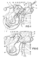
- a cogwheel 1 is actuated with a continuous movement, in a known manner, by a motor and a transmission which are not shown.
- said cogwheel 1 may form part of a fast cam rest (inversion cams) generally used for the control of repetitive sequences, driving a load cam 2 with it.
- the first transport catch 3 acts, whenever it makes a to and fro movement, or in other words, whenever a basic stop interval elapses, on the toothing 7 stiffened to the slow cam rest 8, causing it to move one stage forward in the direction of the arrow 9.
- the first and second transport catches 3 and 4 which may be operatively related to each other, or, as shown in the figures, be formed as a single part, are resiliently attracted in the direction of the arrow 10, figure 1, by the spring 11.
- the temporising mechanism is activated when, upon the one stage forward movement (which distance is equivalent to the angular space between two consecutive cogs of toothing 7), of the slow cam rest 8, the turning centre of slow cam rest 8, the turning centre of the temporising wheel 12, moves from the inactive position 13, to the position 14, figure 2.
- the position of the turning centre of the temporising wheel 12 changes upon actuation of the cam profile 15 stiffened to slow cam rest 8 on the feeler 16 of the selection lever 17 which pivots on the turning axis 18 causing the feeler 16 to move from a "low” position 19 to a "high” position 20.
- the movement of the lever 17 is transmitted to clutch 21, which is in turn rotatingly assembled on an axis 22 stiffened to lever 17 so that the end 23 of the said clutch 21, resting on selection lever 17, pushes an oscillating lever 24 assembled with freedom of rotation on the cogwheel shaft 25.
- the turning axis 13/14 of the temporising wheel 12 is firmly coupled to oscillating lever 24 abutment means, which are not shown, being provided between the axis and the temporising wheel 12 defining a starting point or "zero" position for temporising wheel 12, as well as resilient means, such as a spiral spring, which are not shown either, permanently attracting time wheel 12 towards the starting point abutment, against the direction indicated by the arrow 26 of figure 2.
- the second transport catch 4 becomes related to the temporising wheel 12 penetrating into a hole 27 thereof in order to allow the first transport catch 3 to continue to be in contact with the driving toothing 7 of slow cam rest 8 during the distance travelled by the stage.
- a no return pawl 28 comes in contact with a peripheral toothing 29 of temporising wheel 12, and becomes resiliently related therewith so as to allow it to move forward in the direction of arrow 26 and avoid its returning.
- the no return pawl 28 is comprised by a single part, held in a fixed position by an appendix 44, figure 4, and provided with a resilient area 45 for its operation.
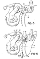
- temporising wheel 12 does not return to zero position and continues to move forward stage by stage until the second transport catch 4 finds a medium depth aperture 35 or a deep aperture 37, figure 6, which may allow the first transport catch to reach toothing 7 of the slow cam rest.
- the temporising interval elapsing until slow cam rest 8 moves forward another stage is the basic interval.
- the clutch 21 has a resilient area 43, figure 7, so that if slow cam rest 8 is unduly actuated on by hand, the feeler 39 of clutch 21 may overcome the internal cam profile 38 without the system being impaired, the feeler and clutch forming a single part.
- the turning centre of temporising wheel 12 moves from position 14 to position 13 without the help of specific means since both retention pawl 28 and the second transport catch 4, when acting on temporising wheel 12, generate a turning moment on the oscillating lever 24 in the suitable direction, having a sufficient magnitude to overcome the friction of the mechanism.
- a pawl 46 which is resiliently applied against driving toothing 7 of slow cam rest 8, figure 6, ensures that the said cam rest is in a suitable position at all times.
- the clutch 21 is coupled by means of a continuous groove 47 on axis 22 stiffened to the selection lever 17, so that, in addition to pivoting about the said axis 22, it maybe displaced along groove 47.
- the cam profile 38 acts on feeler 39 of clutch 21 it releases a projection 48, corresponding to the clutch, from a locking means 49 located in selection lever 17, and the said projection48 then slides along slope 50 of the selection lever 17, driven by the pushing force exerted thereon by oscillating lever 24, to a similar position to that shown in figure 10.
- Rearmament of the system takes place with the help of spline 40 stiffened to the first transport catch 3, as previously described.
- the temporising wheel 12 is superposed to cam rest 8 and is assembled on an oscillating lever 24 which is extended to an end 51 stiffened thereto, on which the clutch acts.
- the temporising wheel 12 is rotatingly assembled on a cylindrical area 52 of oscillating lever 24 and its centre may take up an active position 14 or an inactive position 13.
- a first transport catch 3, shown by the dotted line, is related to driving toothing 7 of slow cam rest 8 and a second transport catch 4 is related to toothing 29 of temporising wheel 12.
- There is also a retention pawl 28 for temporising wheel 12 which comes in contact with the peripheral toothing thereof 29, only when its centre takes up the active position 14.
Landscapes
- Electromechanical Clocks (AREA)
- Transmission Devices (AREA)
- Measurement Of Predetermined Time Intervals (AREA)
Applications Claiming Priority (2)
| Application Number | Priority Date | Filing Date | Title |
|---|---|---|---|
| ES8801260 | 1988-04-25 | ||
| ES8801260A ES2008453A6 (es) | 1988-04-25 | 1988-04-25 | Sistema de accionamiento y temporizacion para dispositivo de mando por programa. |
Publications (2)
| Publication Number | Publication Date |
|---|---|
| EP0340142A2 true EP0340142A2 (de) | 1989-11-02 |
| EP0340142A3 EP0340142A3 (de) | 1991-07-03 |
Family
ID=8256007
Family Applications (1)
| Application Number | Title | Priority Date | Filing Date |
|---|---|---|---|
| EP19890500042 Ceased EP0340142A3 (de) | 1988-04-25 | 1989-04-03 | Steuer- und Zeitschaltungssystem für Vorrichtung mit Zeitschalter |
Country Status (2)
| Country | Link |
|---|---|
| EP (1) | EP0340142A3 (de) |
| ES (1) | ES2008453A6 (de) |
Family Cites Families (3)
| Publication number | Priority date | Publication date | Assignee | Title |
|---|---|---|---|---|
| US3306118A (en) * | 1963-09-07 | 1967-02-28 | Controls Co Of America | Process timers |
| ES417856A1 (es) * | 1973-08-13 | 1976-03-01 | Copreci Ind Sci | Sistema de accionamiento paso a paso de medios de soporte de programas con intervalos de parada seleccionables de du- raciones variables. |
| ES426521A2 (es) * | 1974-05-21 | 1977-06-16 | Copreci Ind Sci | Sistema de accionamiento paso a paso de medios de soporte deprogramas con intervalos de parada seleccionables de dura- ciones variables. |
-
1988
- 1988-04-25 ES ES8801260A patent/ES2008453A6/es not_active Expired
-
1989
- 1989-04-03 EP EP19890500042 patent/EP0340142A3/de not_active Ceased
Also Published As
| Publication number | Publication date |
|---|---|
| EP0340142A3 (de) | 1991-07-03 |
| ES2008453A6 (es) | 1989-07-16 |
Similar Documents
| Publication | Publication Date | Title |
|---|---|---|
| US5211431A (en) | Reciprocating device for movable member | |
| EP0678207B1 (de) | Münzenausgabevorrichtung | |
| NO136826B (no) | Anordning for trykking av typer. | |
| EP0340142A2 (de) | Steuer- und Zeitschaltungssystem für Vorrichtung mit Zeitschalter | |
| GB2232298A (en) | Control devices for microwave ovens | |
| US3955380A (en) | Knitting machine patterning device | |
| US5637843A (en) | Electromechanical programmer/timer | |
| US4471636A (en) | Needle selection device in a circular knitting machine, in particular a hose knitting machine | |
| JPS624977Y2 (de) | ||
| US3412617A (en) | Drive device | |
| US4038837A (en) | Needle selection mechanism for knitting machines | |
| US5780791A (en) | Timer for controlling an appliance having a plurality of pawls which rotate a camstack | |
| US4631972A (en) | Programmer control device | |
| US3237466A (en) | Shaft indexing device | |
| KR20010076290A (ko) | 회전검출장치 | |
| IE49966B1 (en) | Drive coupling arrangements | |
| US3319477A (en) | Timer escapement | |
| US4653343A (en) | Programmer | |
| JPS58104241A (ja) | 電磁的に作動するジヤカ−ド制御装置 | |
| US3056307A (en) | Mechanism for coin-operated timer | |
| US3228562A (en) | Automatic timing and dispensing device | |
| US3563025A (en) | Clock mechanism | |
| US4566347A (en) | Programmer | |
| SU496749A3 (ru) | Приводное устройство внутреннего колодочного тормоза | |
| JPH0743802Y2 (ja) | レバー駆動機構 |
Legal Events
| Date | Code | Title | Description |
|---|---|---|---|
| PUAI | Public reference made under article 153(3) epc to a published international application that has entered the european phase |
Free format text: ORIGINAL CODE: 0009012 |
|
| AK | Designated contracting states |
Kind code of ref document: A2 Designated state(s): DE FR GB IT |
|
| PUAL | Search report despatched |
Free format text: ORIGINAL CODE: 0009013 |
|
| AK | Designated contracting states |
Kind code of ref document: A3 Designated state(s): DE FR GB IT |
|
| 17P | Request for examination filed |
Effective date: 19910919 |
|
| 17Q | First examination report despatched |
Effective date: 19931202 |
|
| STAA | Information on the status of an ep patent application or granted ep patent |
Free format text: STATUS: THE APPLICATION HAS BEEN REFUSED |
|
| 18R | Application refused |
Effective date: 19950807 |