EP0340123A1 - Isoliertes Rohrelement zur Errichtung von oberirdischen Flüssigkeitstransporteinrichtungen, Verfahren zur Errichtung sowie Einrichtungen aus solchen Elementen - Google Patents
Isoliertes Rohrelement zur Errichtung von oberirdischen Flüssigkeitstransporteinrichtungen, Verfahren zur Errichtung sowie Einrichtungen aus solchen Elementen Download PDFInfo
- Publication number
- EP0340123A1 EP0340123A1 EP89420134A EP89420134A EP0340123A1 EP 0340123 A1 EP0340123 A1 EP 0340123A1 EP 89420134 A EP89420134 A EP 89420134A EP 89420134 A EP89420134 A EP 89420134A EP 0340123 A1 EP0340123 A1 EP 0340123A1
- Authority
- EP
- European Patent Office
- Prior art keywords
- tube
- envelope
- layer
- tubular element
- installation
- Prior art date
- Legal status (The legal status is an assumption and is not a legal conclusion. Google has not performed a legal analysis and makes no representation as to the accuracy of the status listed.)
- Withdrawn
Links
- 238000009434 installation Methods 0.000 title claims abstract description 48
- 238000000034 method Methods 0.000 title description 6
- 238000009413 insulation Methods 0.000 claims abstract description 28
- 239000000463 material Substances 0.000 claims abstract description 13
- 229910052751 metal Inorganic materials 0.000 claims abstract description 11
- 239000002184 metal Substances 0.000 claims abstract description 11
- 230000001681 protective effect Effects 0.000 claims abstract description 9
- 238000004804 winding Methods 0.000 claims abstract description 5
- 239000012212 insulator Substances 0.000 claims abstract description 4
- 229910052782 aluminium Inorganic materials 0.000 claims description 8
- XAGFODPZIPBFFR-UHFFFAOYSA-N aluminium Chemical compound [Al] XAGFODPZIPBFFR-UHFFFAOYSA-N 0.000 claims description 8
- 238000012423 maintenance Methods 0.000 claims description 7
- 238000004519 manufacturing process Methods 0.000 claims description 7
- 230000000903 blocking effect Effects 0.000 claims description 6
- 239000011810 insulating material Substances 0.000 claims description 5
- 238000009421 internal insulation Methods 0.000 claims description 4
- 239000011888 foil Substances 0.000 claims description 2
- 238000010348 incorporation Methods 0.000 claims description 2
- 239000012530 fluid Substances 0.000 description 13
- 239000011490 mineral wool Substances 0.000 description 4
- 239000000243 solution Substances 0.000 description 4
- 229920005830 Polyurethane Foam Polymers 0.000 description 3
- 230000000712 assembly Effects 0.000 description 3
- 238000000429 assembly Methods 0.000 description 3
- 239000011496 polyurethane foam Substances 0.000 description 3
- 238000010079 rubber tapping Methods 0.000 description 3
- 238000012546 transfer Methods 0.000 description 3
- 230000006978 adaptation Effects 0.000 description 2
- 230000006835 compression Effects 0.000 description 2
- 238000007906 compression Methods 0.000 description 2
- 239000006260 foam Substances 0.000 description 2
- 239000011491 glass wool Substances 0.000 description 2
- 238000007689 inspection Methods 0.000 description 2
- 238000012795 verification Methods 0.000 description 2
- 229910001335 Galvanized steel Inorganic materials 0.000 description 1
- 239000000853 adhesive Substances 0.000 description 1
- 230000001070 adhesive effect Effects 0.000 description 1
- 239000010425 asbestos Substances 0.000 description 1
- 239000000919 ceramic Substances 0.000 description 1
- 239000011248 coating agent Substances 0.000 description 1
- 238000000576 coating method Methods 0.000 description 1
- 238000010276 construction Methods 0.000 description 1
- 230000001934 delay Effects 0.000 description 1
- 238000010586 diagram Methods 0.000 description 1
- 239000000835 fiber Substances 0.000 description 1
- 239000008397 galvanized steel Substances 0.000 description 1
- 239000003292 glue Substances 0.000 description 1
- 238000002347 injection Methods 0.000 description 1
- 239000007924 injection Substances 0.000 description 1
- 238000012986 modification Methods 0.000 description 1
- 230000004048 modification Effects 0.000 description 1
- 230000000737 periodic effect Effects 0.000 description 1
- 239000000843 powder Substances 0.000 description 1
- 229910052895 riebeckite Inorganic materials 0.000 description 1
- 229910000648 terne Inorganic materials 0.000 description 1
- 238000012360 testing method Methods 0.000 description 1
- 238000003466 welding Methods 0.000 description 1
Images

Classifications
-
- F—MECHANICAL ENGINEERING; LIGHTING; HEATING; WEAPONS; BLASTING
- F16—ENGINEERING ELEMENTS AND UNITS; GENERAL MEASURES FOR PRODUCING AND MAINTAINING EFFECTIVE FUNCTIONING OF MACHINES OR INSTALLATIONS; THERMAL INSULATION IN GENERAL
- F16L—PIPES; JOINTS OR FITTINGS FOR PIPES; SUPPORTS FOR PIPES, CABLES OR PROTECTIVE TUBING; MEANS FOR THERMAL INSULATION IN GENERAL
- F16L59/00—Thermal insulation in general
- F16L59/08—Means for preventing radiation, e.g. with metal foil
-
- F—MECHANICAL ENGINEERING; LIGHTING; HEATING; WEAPONS; BLASTING
- F16—ENGINEERING ELEMENTS AND UNITS; GENERAL MEASURES FOR PRODUCING AND MAINTAINING EFFECTIVE FUNCTIONING OF MACHINES OR INSTALLATIONS; THERMAL INSULATION IN GENERAL
- F16L—PIPES; JOINTS OR FITTINGS FOR PIPES; SUPPORTS FOR PIPES, CABLES OR PROTECTIVE TUBING; MEANS FOR THERMAL INSULATION IN GENERAL
- F16L59/00—Thermal insulation in general
- F16L59/14—Arrangements for the insulation of pipes or pipe systems
- F16L59/143—Pre-insulated pipes
-
- F—MECHANICAL ENGINEERING; LIGHTING; HEATING; WEAPONS; BLASTING
- F16—ENGINEERING ELEMENTS AND UNITS; GENERAL MEASURES FOR PRODUCING AND MAINTAINING EFFECTIVE FUNCTIONING OF MACHINES OR INSTALLATIONS; THERMAL INSULATION IN GENERAL
- F16L—PIPES; JOINTS OR FITTINGS FOR PIPES; SUPPORTS FOR PIPES, CABLES OR PROTECTIVE TUBING; MEANS FOR THERMAL INSULATION IN GENERAL
- F16L59/00—Thermal insulation in general
- F16L59/14—Arrangements for the insulation of pipes or pipe systems
- F16L59/16—Arrangements specially adapted to local requirements at flanges, junctions, valves or the like
- F16L59/18—Arrangements specially adapted to local requirements at flanges, junctions, valves or the like adapted for joints
- F16L59/20—Arrangements specially adapted to local requirements at flanges, junctions, valves or the like adapted for joints for non-disconnectable joints
Definitions
- the present invention relates to a new type of insulated tubular element allowing the realization of aerial installations conveying fluids, and more particularly fluids at high temperature; it also relates to a process allowing the production of such elements as well as to the installations which they make it possible to produce.
- the invention aims to solve these problems and relates, in summary, to an improvement made to such types of tubular elements, in particular straight lengths, the insulation of which is carried out entirely in the workshop and which makes it possible to obtain installations.
- aerials conveying fluids in which only the accessories and the connection zones between the elementary tubular elements will be insulated on the site, this insulation being also made using removable assemblies, also manufactured and insulated in the workshop and which are put in place, after verification and technical control, said assemblies which can also be dismantled to carry out periodic verifications or maintenance.
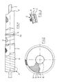
- the tubular element according to the invention is in the form of a tube of determined length, covered with an external envelope ensuring its protection, and comprising an internal insulation layer disposed between said envelope external and the internal tube, said external envelope and the intermediate insulator not covering the internal tube over its entire length so as to leave at each end a stripped part allowing the connection of the elementary tubes between them to carry out the installation and / or the interposition of various accessories between two consecutive tubes.
- the tubular element according to the invention is used for the insulation of tubes inside which circulates a fluid at low temperature (below 90 ° C. ), in which case the layer of blocking foam of the external envelope against the tube can itself serve as an insulating layer and extend over the entire space located between the envelope and said tube, according to a preferred embodiment according to the invention according to which the tubular elements are used for the insulation of installations in which fluids circulate at high temperature (several hundred degrees), the internal tube will be covered with a layer (shell) insulating material of determined thickness (glass wool, rock wool, or any other insulating material), said layer being applied against the internal tube by means of an adhesive resistant to high temperature and being covered by a strip allowing it to be made up of the heat transfer tube.
- a layer (shell) insulating material of determined thickness glass wool, rock wool, or any other insulating material
- a reflective aluminum sheet is, prior to the installation of the outer sheath and final connection, wound around the insulation layer according to the "spiral" technique.
- the elements ensuring the spacing and the centering of the external envelope with respect to the internal core consist of rings distributed regularly over the entire length of the elementary tube and comprising spikes.
- the layer of expanded material ensuring the connection of the assembly defined above with the outer envelope consisting of a spiral winding of metal sheets stapled edge to edge is constituted for example by a layer of expanded polyurethane foam.
- the process for producing such an elementary tube is apparent from the above description and generally consists in surrounding the internal tube with a layer of insulating material, in ensuring the maintenance of said layer around the tube, in positioning the centering and spacing elements around the assembly thus formed which is then covered with the outer spiral sheath, the injection of expandable material then being carried out to ensure the maintenance and final blocking of said sheath.
- the installations made from such elementary tubes are characterized in that these tubes are welded end to end by their stripped part with possibly incorporation of accessories between two tubes (valves, taps, etc.), the stripped areas thus connected being, after complete realization of the installation, themselves covered with suitable protective and insulating covers, also prefabricated.
- the insulated tubular element according to the invention essentially consists of an internal tube (1), of determined length.
- a layer of a high temperature resistant glue which serves to hold rock wool shells (2), serving as insulation proper or any other equivalent material .
- These shells (2) can optionally be tightened mechanically by a strip in order to really form a block with the heat transfer tube (1).
- an aluminum foil (3) thermo reflector wound spiral around the insulation (2).
- collars (4) which have on their periphery of the pins (4a) of determined height, regularly spaced each other.
- the height of the pins (4a) is equal to the difference of the diameter of the outer protective tube (6) with the diameter of the insulated tube coated with the aluminum sheet described above. In this way, a perfect centering of the different elements is achieved.
- the diameter of the protective tube (6) is, as said above, greater than the diameter obtained after the installation of the reflective screen (3) made of aluminum, in order to be able to inject into the space thus provided an expandable material ( 5), for example a polyurethane foam which, during expansion, ensures a perfect connection between the internal insulation (2,3) and the external coating (6) (see Figures 2 and 3).
- an expandable material ( 5) for example a polyurethane foam which, during expansion, ensures a perfect connection between the internal insulation (2,3) and the external coating (6) (see Figures 2 and 3).
- the main function of injecting polyurethane foam is to make the whole integral, taking into account that during expansion, tensions occur in all directions, ensuring not only perfect blocking and immobilization of the outer sheath, but also of the intermediate insulation around the heat transfer tube.
- this layer of foam further improves the insulation.
- the first tubular element (1a) is connected to the second tubular element (1b) by means of flanges (10).
- the end of the tubular element (1b) is connected directly to the end of an element (1c) so as to form a continuous rectilinear part.
- the element (1c) is associated with a tapping (12) produced over its length and its end is connected to an element (1d), itself extended by an elbow-shaped part (11).
- FIG. 6 illustrates an insulating box comprising a hinge and intended to be attached to the consecutive delimited ends of two tubes according to the invention in the junction zones. This box therefore makes it possible to carry out a posteriori checks.
- FIG. 7 illustrates an embodiment of a housing for an area comprising a tapping
- FIG. 8 a removable housing for butt welds
- FIG. 9, a housing also removable for the areas comprising flanges.
- tubular elements according to the invention it is therefore possible to obtain perfectly insulated installations. Furthermore, the insulation of the stripped parts, the accessories, etc. by means of removable boxes has an important advantage in technical inspection maintenance work on the installations, in the sense that there is no longer any need to dismantle all insulation to x-ray welds or elbows. The only dismantling of the case therefore makes it possible to carry out these works in very good conditions.
- the tubular elements according to the invention have very numerous advantages in that in the traditional system, the insulation work could only be carried out after all controls, which therefore lengthened the duration of the worksites.
- the invention it is possible to carry out the start-up immediately after the control tests since about 90% of the entire installation is already isolated. This allows an immediate production gain to the end user of the industrial installation.
- tubular elements considerably reduce the transport costs since previously the insulating shells and the tubes themselves were transported separately and therefore the vacuum inside the shells (2) was lost while , thanks to the invention, it is filled with the inner tube.
- the elements in accordance with the invention moreover ensure perfect weathertightness and above all the insulation work is carried out with very high security, since they are carried out in the workshop and protected from the weather by qualified personnel. , which is not always the case when the insulation is carried out directly on the site.
- the invention is not limited to the embodiment described above, but it covers all the variants produced in the same spirit.
- a type of tubular material could be used for other types of installations than those conveying fluids, for example as a protective sheath in installations comprising tubes transporting hot powders, as a protective element in particular against fire, for electric cables, or even for other applications, thanks to the nature of the materials used in the constitution of such a tubular element.
- the intermediate insulating layer can be chosen according to the applications, this layer possibly being based on any suitable material, such as glass or rock wool, asbestos, ceramic fibers, etc.
Landscapes
- Engineering & Computer Science (AREA)
- General Engineering & Computer Science (AREA)
- Mechanical Engineering (AREA)
- Thermal Insulation (AREA)
- Laminated Bodies (AREA)
Applications Claiming Priority (2)
| Application Number | Priority Date | Filing Date | Title |
|---|---|---|---|
| FR8805422A FR2630191B1 (fr) | 1988-04-19 | 1988-04-19 | Element tubulaire isole pour la realisation d'installations aeriennes vehiculant des fluides, procede pour sa realisation et installations constituees de tels elements |
| FR8805422 | 1988-04-19 |
Publications (1)
| Publication Number | Publication Date |
|---|---|
| EP0340123A1 true EP0340123A1 (de) | 1989-11-02 |
Family
ID=9365617
Family Applications (1)
| Application Number | Title | Priority Date | Filing Date |
|---|---|---|---|
| EP89420134A Withdrawn EP0340123A1 (de) | 1988-04-19 | 1989-04-14 | Isoliertes Rohrelement zur Errichtung von oberirdischen Flüssigkeitstransporteinrichtungen, Verfahren zur Errichtung sowie Einrichtungen aus solchen Elementen |
Country Status (4)
| Country | Link |
|---|---|
| EP (1) | EP0340123A1 (de) |
| FR (1) | FR2630191B1 (de) |
| OA (1) | OA09071A (de) |
| TN (1) | TNSN89049A1 (de) |
Cited By (3)
| Publication number | Priority date | Publication date | Assignee | Title |
|---|---|---|---|---|
| WO1990014552A1 (en) * | 1989-05-25 | 1990-11-29 | Bakelittfabrikken A/S | Method for producing long, isolated pipes in the form of a sandwich construction |
| WO1992019899A1 (en) * | 1991-04-30 | 1992-11-12 | Oy Kwh Pipe Ab | A method for isolating a spirally wound pipe |
| EP2151618A3 (de) * | 2008-08-06 | 2012-07-04 | GWK Kuhlmann GmbH | Vorrichtung zur Isolierung eines Rohrleitungssystems |
Citations (4)
| Publication number | Priority date | Publication date | Assignee | Title |
|---|---|---|---|---|
| US2857931A (en) * | 1955-03-24 | 1958-10-28 | R W Mfg Co | Insulated pipe and method of making the same |
| DE2203312A1 (de) * | 1972-01-25 | 1973-08-02 | Wrede & Niedecken Gmbh | Isoliermantel, insbesondere zur kaelteisolierung von behaeltern, rohrleitungen und dergleichen und verfahren zu seiner herstellung |
| FR2257059A1 (en) * | 1974-01-07 | 1975-08-01 | Insta Foam Prod Inc | Apparatus for sheathed, insulated pipe prodn - with cover-shaping, joint-forming pipe-guiding and foam-supplying devices |
| DE3043450A1 (de) * | 1979-12-20 | 1981-08-20 | Josef Linz Gfrerer | Erdverlegte rohrleitung fuer fernheizungen |
Family Cites Families (1)
| Publication number | Priority date | Publication date | Assignee | Title |
|---|---|---|---|---|
| DE2844223A1 (de) * | 1978-10-11 | 1980-04-24 | Gruenzweig & Hartmann Montage | Waermegedaemmtes rohr |
-
1988
- 1988-04-19 FR FR8805422A patent/FR2630191B1/fr not_active Expired - Fee Related
-
1989
- 1989-04-14 EP EP89420134A patent/EP0340123A1/de not_active Withdrawn
- 1989-04-18 OA OA59566A patent/OA09071A/xx unknown
- 1989-04-19 TN TNTNSN89049A patent/TNSN89049A1/fr unknown
Patent Citations (4)
| Publication number | Priority date | Publication date | Assignee | Title |
|---|---|---|---|---|
| US2857931A (en) * | 1955-03-24 | 1958-10-28 | R W Mfg Co | Insulated pipe and method of making the same |
| DE2203312A1 (de) * | 1972-01-25 | 1973-08-02 | Wrede & Niedecken Gmbh | Isoliermantel, insbesondere zur kaelteisolierung von behaeltern, rohrleitungen und dergleichen und verfahren zu seiner herstellung |
| FR2257059A1 (en) * | 1974-01-07 | 1975-08-01 | Insta Foam Prod Inc | Apparatus for sheathed, insulated pipe prodn - with cover-shaping, joint-forming pipe-guiding and foam-supplying devices |
| DE3043450A1 (de) * | 1979-12-20 | 1981-08-20 | Josef Linz Gfrerer | Erdverlegte rohrleitung fuer fernheizungen |
Cited By (4)
| Publication number | Priority date | Publication date | Assignee | Title |
|---|---|---|---|---|
| WO1990014552A1 (en) * | 1989-05-25 | 1990-11-29 | Bakelittfabrikken A/S | Method for producing long, isolated pipes in the form of a sandwich construction |
| GB2232221B (en) * | 1989-05-25 | 1993-11-03 | Bakelittfab As | Pipe insulation method |
| WO1992019899A1 (en) * | 1991-04-30 | 1992-11-12 | Oy Kwh Pipe Ab | A method for isolating a spirally wound pipe |
| EP2151618A3 (de) * | 2008-08-06 | 2012-07-04 | GWK Kuhlmann GmbH | Vorrichtung zur Isolierung eines Rohrleitungssystems |
Also Published As
| Publication number | Publication date |
|---|---|
| TNSN89049A1 (fr) | 1991-02-04 |
| OA09071A (fr) | 1991-10-31 |
| FR2630191A1 (fr) | 1989-10-20 |
| FR2630191B1 (fr) | 1990-06-08 |
Similar Documents
| Publication | Publication Date | Title |
|---|---|---|
| EP0060856B1 (de) | Verfahren zum verstärken eines hohlkörpers durch wickeln eines formstückes, formstück für seine durchführung und hergestellte verstärkte kanalisation | |
| EP0329549B1 (de) | Isoliermatte für gekrümmte Körper, insbesonere für Rohre sowie Verwendung | |
| FR2468063A1 (fr) | Conduit calorifuge pour le transport de fluides | |
| FR2593929A1 (fr) | Cable a fibres optiques | |
| CA2681544C (fr) | Installation et procede de fabrication en continu d'un tube ou d'un cable isole thermiquement ou electriquement, tube ou cable ainsi obtenu et application a la realisation de tuyaux double enveloppe | |
| WO2000032978A1 (fr) | Procede de raccordement de deux tubes en materiau thermoplastique renforce | |
| FR2542060A1 (fr) | Tuyau conducteur isole de la chaleur et procede pour le fabriquer | |
| EP0402201A2 (de) | Mit einer profilierten Umhüllung versehener Draht, insbesondere zum Formen eines Elektro-Schweiss-Einsatzes | |
| FR2673264A1 (fr) | Conduite pour le transport de fluides, en particulier d'hydrocarbures. | |
| FR2486665A1 (fr) | Methode de raccordement de cables armes, notamment des cables sous-marins a fibres optiques, et epissure des fils d'armure de tels cables | |
| EP0340123A1 (de) | Isoliertes Rohrelement zur Errichtung von oberirdischen Flüssigkeitstransporteinrichtungen, Verfahren zur Errichtung sowie Einrichtungen aus solchen Elementen | |
| EP3365591B1 (de) | Verfahren zur montage einer starren rohrleitung und zugehörige rohrleitung | |
| WO1998034061A1 (fr) | Enveloppe d'isolation thermique, notamment pour la construction de canalisations sous-marines vehiculant des produits petroliers | |
| FR2627026A1 (fr) | Procede pour realiser l'etancheite entre un cable ou element analogue et une conduite externe recevant ce cable et bande composite pour la mise en oeuvre de ce procede | |
| FR2664850A1 (fr) | Procede de gainage d'un faisceau d'elements filiformes, dispositif pour le mettre en óoeuvre et faisceau obtenu. | |
| FR2751721A1 (fr) | Procede de montage de canalisations par assemblage en mer de tuyaux successifs, et tuyaux pour la mise en oeuvre de ce procede | |
| FR2674720A1 (fr) | Vitrage feuillete chauffant. | |
| FR2598772A1 (fr) | Tube de canalisation isole thermiquement, a deux conducteurs sans disposition pour la dilatation, procede et dispositif de leur mise en oeuvre. | |
| FR2535570A1 (fr) | Bande a chauffage electrique pour la realisation d'une jonction par manchon pour canalisation tubulaire thermiquement isolee, et son procede de fabrication | |
| FR2514293A1 (fr) | Procede de fabrication de bagues d'isolation pour les supports de tuyaux | |
| FR2548588A1 (fr) | Procede pour realiser un systeme rigide de tubes constitue d'au moins deux tubes metalliques concentriques | |
| BE898133A (fr) | Groupe guide-cables. | |
| BE845136R (fr) | Support utilisable dans une tuyauterie de transport souterrain de fluides caloporteurs | |
| FR2507230A1 (fr) | Profil metallique longitudinal et installation du circuit absorbeur de pompe a chaleur | |
| FR2782188A1 (fr) | Cable de liaison a isolation gazeuse, procede de fabrication et de pose d'un tel cable |
Legal Events
| Date | Code | Title | Description |
|---|---|---|---|
| PUAI | Public reference made under article 153(3) epc to a published international application that has entered the european phase |
Free format text: ORIGINAL CODE: 0009012 |
|
| AK | Designated contracting states |
Kind code of ref document: A1 Designated state(s): AT BE DE ES GB IT NL SE |
|
| 17P | Request for examination filed |
Effective date: 19900329 |
|
| 17Q | First examination report despatched |
Effective date: 19910104 |
|
| STAA | Information on the status of an ep patent application or granted ep patent |
Free format text: STATUS: THE APPLICATION IS DEEMED TO BE WITHDRAWN |
|
| 18D | Application deemed to be withdrawn |
Effective date: 19930703 |