EP0340074B1 - Plattformanlage für Transportfahrzeuge - Google Patents
Plattformanlage für Transportfahrzeuge Download PDFInfo
- Publication number
- EP0340074B1 EP0340074B1 EP19890401065 EP89401065A EP0340074B1 EP 0340074 B1 EP0340074 B1 EP 0340074B1 EP 19890401065 EP19890401065 EP 19890401065 EP 89401065 A EP89401065 A EP 89401065A EP 0340074 B1 EP0340074 B1 EP 0340074B1
- Authority
- EP
- European Patent Office
- Prior art keywords
- rails
- platform
- floor
- vehicle
- transport vehicles
- Prior art date
- Legal status (The legal status is an assumption and is not a legal conclusion. Google has not performed a legal analysis and makes no representation as to the accuracy of the status listed.)
- Expired - Lifetime
Links
- 238000009434 installation Methods 0.000 claims description 10
- 239000002184 metal Substances 0.000 description 1
- 238000000034 method Methods 0.000 description 1
- 230000000284 resting effect Effects 0.000 description 1
- 238000005096 rolling process Methods 0.000 description 1
Images

Classifications
-
- B—PERFORMING OPERATIONS; TRANSPORTING
- B60—VEHICLES IN GENERAL
- B60P—VEHICLES ADAPTED FOR LOAD TRANSPORTATION OR TO TRANSPORT, TO CARRY, OR TO COMPRISE SPECIAL LOADS OR OBJECTS
- B60P1/00—Vehicles predominantly for transporting loads and modified to facilitate loading, consolidating the load, or unloading
- B60P1/02—Vehicles predominantly for transporting loads and modified to facilitate loading, consolidating the load, or unloading with parallel up-and-down movement of load supporting or containing element
-
- B—PERFORMING OPERATIONS; TRANSPORTING
- B60—VEHICLES IN GENERAL
- B60P—VEHICLES ADAPTED FOR LOAD TRANSPORTATION OR TO TRANSPORT, TO CARRY, OR TO COMPRISE SPECIAL LOADS OR OBJECTS
- B60P1/00—Vehicles predominantly for transporting loads and modified to facilitate loading, consolidating the load, or unloading
- B60P1/52—Vehicles predominantly for transporting loads and modified to facilitate loading, consolidating the load, or unloading using rollers in the load-transporting element
Definitions
- the present invention relates to the layout of transport vehicles such as trucks.
- the invention relates more particularly to vehicles which are intended to be loaded with boxes carried by carts rolled from a loading dock inside the vehicles.
- the loading of a vehicle is prepared on a quay by placing said loading on one or more trolleys, trolleys which are rolled in the vehicle then which are then brought back to the quay for another loading.
- One of the difficulties of such systems is to release the carts from the load when they are placed in the vehicle.
- the raceways are in a high position and serve as a guide for the trolley wheels.
- the raceways are lowered, the load resting on the rails, and the carriages can thus be released.
- Such an arrangement is described in particular in CH-A-568 910.
- One of the aims of the present invention is to remedy these various drawbacks.
- the installation according to the invention is of the type comprising longitudinal guide rails for carriages carrying loads to be inserted into a vehicle and means for releasing the carriages when the loads are placed in the vehicle and is characterized in that that it comprises between two guide rails corresponding to the two carriages supporting a load, a floor carried by vertically movable supports, means being provided for controlling the lifting of the floor so that it can occupy a low loading position and a high position in order to raise the load to disengage the carriages.
- the plate comprises profiles with C section extending parallel to the rails and having a core integral with said plate, two wings and two returns, in these profiles being housed supports of substantially rectangular section with two large sides, the length corresponds substantially to the interval separating the returns, and the short sides of which are extended by wings turned towards the outside and intended, on the one hand, to cooperate with the web of the profile when the floor is in the low position and, on the other hand, to constitute stops when the floor is in the high position, an inflatable tube being inserted between the core of the profiles and the corresponding supports and the floor being fixed on said supports.
- the installation comprises two rails mounted in the middle part of the vehicle tray and two rails provided along the longitudinal edges of said tray and two movable floors arranged on either side of the two rails of the middle part .
- the two rails of the middle part of the vehicle platform are hollow and produced in profiles having projecting parts located at the floors when these are in the low position.
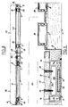
- the reference 1 designates the platform of a transport vehicle such as a truck.
- the platform 1 comprises guide rails 2 and 3 which are produced from a metal section 4 suitably bent.
- guide rails 5 and 6 made from profiles.
- each section 7 is housed a movable support 8 consisting of a section of substantially rectangular section whose long sides 8a and 8b have a length corresponding to the interval between the free ends of the returns 7c, while the short sides are extended by wings 9 facing outwards and intended, on the one hand, to rest on the core 7a and, on the other hand, to constitute stops by cooperating with the returns 7c.
- a movable support 8 consisting of a section of substantially rectangular section whose long sides 8a and 8b have a length corresponding to the interval between the free ends of the returns 7c, while the short sides are extended by wings 9 facing outwards and intended, on the one hand, to rest on the core 7a and, on the other hand, to constitute stops by cooperating with the returns 7c.
- each section 8 is such that when the wings 9 bear against the core 7a the outer surface of the returns 7c and the outer surface of the large side 8a are located in the same plane.
- the rails 2 and 3 are hollow and the floor 11 is located at the same level as the rails 6 and the raised portions bordering the rails 2 and 3.
- inflatable tubes 15 which can be connected either to a compressor provided directly on the vehicle, or to a source of external compressed air, for example a source of compressed air provided on a loading dock.
- a loading dock comprising, itself, guide rails which are aligned with the rails 2, 3, 5 and 6 when loading.
- the loads to be transported are prepared which are placed on carriages 19, the vehicle to be loaded being placed in front of the dock and the rails 2, 3, 5 and 6 aligned with the rails of the dock.
- the floors 11 and 12 are kept in the low position and the carriages 19 rolled so that the loads 16 and 17 are housed in the vehicle.
- the floor 12 is then raised, compressed air being sent into the corresponding tubes 15 so that the load 17 is released from the carriages 19 which can thus be removed (fig. 3).
Landscapes
- Engineering & Computer Science (AREA)
- Transportation (AREA)
- Mechanical Engineering (AREA)
- Loading Or Unloading Of Vehicles (AREA)
- Ship Loading And Unloading (AREA)
Claims (4)
- Einrichtung für Ladeflächen von Transportfahrzeugen, die längsverlaufende Führungsschienen für Laufkarren aufweist, die Ladegüter tragen, die in ein Fahrzeug einzuladen sind, und mit Mitteln zur Freigabe der Laufkarren, wenn die Ladegüter in dem Fahrzeug an ihrem Platz sind, dadurch gekennzeichnet, daß sie zwischen zwei Führungsschienen (2-6), die zwei ein Ladegut tragenden Laufkarren angepaßt sind, eine Platte (11, 12) aufweist, die durch vertikal bewegliche Träger (8) getragen ist, und daß Mittel (15) vorgesehen sind, um das Anheben der Platte (11) in der Weise zu steuern, daß diese eine abgesenkte Beladestellung und eine angehobene Stellung einnehmen kann, um das Ladegut (16-17) für das Freigeben der Laufkarren (19) anzuheben.
- Einrichtung für Ladeflächen von Transportfahrzeugen gemäß Anspruch 1, dadurch gekennzeichnet, daß die Ladefläche (1) Profile (7) mit C-förmigem Querschnitt aufweist, die sich parallel zu den Führungsschienen (2-6) erstrecken und einen mit der genannten Ladefläche verbundenen Steg (7a), zwei Schenkel (7b) und zwei vorspringende Teile (7c) aufweist, daß in diesen Profilen Träger (8) mit einem im wesentlichen rechteckigen Querschnitt aufgenommen sinc, deren beide großflächigen Seiten (8a, 8b) eine Länge besitzen, die im wesentlichen dem Abstand zwischen den vorspringenden Profilteilen (7c) entspricht, und deren Schmalseiten durch Flügel (9) verlängert sind, die nach auswärts gerichtet und dazu bestimmt sind, um einerseits mit dem Steg des Profils zusammenzuwirken, wenn die Platte in der abgesenkten Stellung ist, und um andererseits Anschläge zu bilden, wenn die Platte in der angehobenen Stellung ist, daß ein aufblasbarer Wulst (15) zwischen den Steg (7a) der Profile (7) und die entsprechenden Träger (8) eingelegt ist und daß die Platte (11) auf den genannten Trägern (8) befestigt ist.
- Einrichtung für Ladeflächen von Transportfahrzeugen gemäß Anspruch 1, dadurch gekennzeichnet, daß sie zwei Führungsschienen (2 und 3), die im mittleren Teil der Ladefläche des Fahrzeuges angeordnet sind, und zwei Führungsschienen (5 und 6), die entlang der längsverlaufenden Ränder der genannten Ladefläche (1) vorgesehen sind, sowie zwei bewegliche Platten (11, 12) aufweist, von denen je eine auf der einen und der anderen Seite der zwei Führungsschienen (2, 3) des mittleren Teils angeordnet ist.
- Einrichtung für Ladeflächen von Transportfahrzeugen gemäß Anspruch 3, dadurch gekennzeichnet, daß die zwei Führungsschienen (2, 3) des mittleren Teils der Ladefläche (1) des Fahrzeugs als Vertiefungen in Profilstücken (4) ausgebildet sind, die vorstehende Teile aufweisen, die das Niveau der Platten (11, 12) in ihrer abgesenkten Stellung einnehmen.
Applications Claiming Priority (2)
| Application Number | Priority Date | Filing Date | Title |
|---|---|---|---|
| FR8805616 | 1988-04-27 | ||
| FR8805616A FR2630688B1 (fr) | 1988-04-27 | 1988-04-27 | Installation de plateaux de vehicules de transport |
Publications (2)
| Publication Number | Publication Date |
|---|---|
| EP0340074A1 EP0340074A1 (de) | 1989-11-02 |
| EP0340074B1 true EP0340074B1 (de) | 1992-10-07 |
Family
ID=9365746
Family Applications (1)
| Application Number | Title | Priority Date | Filing Date |
|---|---|---|---|
| EP19890401065 Expired - Lifetime EP0340074B1 (de) | 1988-04-27 | 1989-04-18 | Plattformanlage für Transportfahrzeuge |
Country Status (3)
| Country | Link |
|---|---|
| EP (1) | EP0340074B1 (de) |
| DE (1) | DE68903129D1 (de) |
| FR (1) | FR2630688B1 (de) |
Families Citing this family (3)
| Publication number | Priority date | Publication date | Assignee | Title |
|---|---|---|---|---|
| GB2309448B (en) * | 1996-01-24 | 2000-03-29 | Shotton Paper Company Plc | Vehicle with improved loading/unloading apparatus |
| DE29704533U1 (de) * | 1997-03-13 | 1997-06-26 | Georg Robel GmbH & Co, 81371 München | Zwischenlage zur Höhenmäßigen Distanzierung und Abstützung von Langschienen |
| GB9713432D0 (en) * | 1997-06-25 | 1997-08-27 | Hydraroll Ltd | A support |
Family Cites Families (3)
| Publication number | Priority date | Publication date | Assignee | Title |
|---|---|---|---|---|
| US2678139A (en) * | 1951-08-25 | 1954-05-11 | Alfred M Gildersleeve | Trailer or like body freight loading device |
| JPS5237419Y2 (de) * | 1973-02-22 | 1977-08-25 | ||
| GB2139982B (en) * | 1983-05-16 | 1987-01-14 | Hydraroll Ltd | Load handling apparatus |
-
1988
- 1988-04-27 FR FR8805616A patent/FR2630688B1/fr not_active Expired - Lifetime
-
1989
- 1989-04-18 DE DE8989401065T patent/DE68903129D1/de not_active Expired - Lifetime
- 1989-04-18 EP EP19890401065 patent/EP0340074B1/de not_active Expired - Lifetime
Also Published As
| Publication number | Publication date |
|---|---|
| FR2630688A1 (fr) | 1989-11-03 |
| EP0340074A1 (de) | 1989-11-02 |
| DE68903129D1 (de) | 1992-11-12 |
| FR2630688B1 (fr) | 1990-07-27 |
Similar Documents
| Publication | Publication Date | Title |
|---|---|---|
| EP0199652B1 (de) | Container-Verladevorrichtung | |
| FR2732958A1 (fr) | Chariot automoteur a fourches telescopiques pour la desserte d'un magasin de stockage de charges sur palettes et magasin de stockage | |
| FR2774083A1 (fr) | Dispositif elevateur perfectionne | |
| EP3248836A1 (de) | Transport- und nutzfahrzeug, mobile logistikbasis, die ein solches fahrzeug umfasst, und zelle für ein solches fahrzeug | |
| EP0553086A1 (de) | Selbsthebender gabelstapler | |
| EP0340074B1 (de) | Plattformanlage für Transportfahrzeuge | |
| EP0024996B1 (de) | Container für offenen Lastkraftwagen und für die Aufnahme eines solchen Containers vorgesehener Lastkraftwagen | |
| EP4410712B1 (de) | Hubtisch zur handhabung mit automatischer niveaueinstellung | |
| EP4446253A1 (de) | Wartungssystem für transport- und lageranlage | |
| FR2631948A1 (fr) | Chariot de manutention automatique de charges lourdes a distribution bilaterale | |
| EP2253562B1 (de) | Transportvorrichtung für vorgefertigte plattenförmige Elemente | |
| FR2850929A3 (fr) | Dispositif pour le transport ferroviaire de vehicules de type poids lourds | |
| EP1232904A1 (de) | Gütertransportfahrzeug mit einer Hubplattform | |
| EP1091161B1 (de) | Halte- und Abstellvorrichtung für Gasflaschen | |
| FR2828457A1 (fr) | Vehicules et rames ferroviaires ou routiers a niveau variable induit par roulement accessoire pour transports a grand gabarit | |
| EP4166389B1 (de) | Handhabungssystem für ein fahrzeug | |
| EP3760482A1 (de) | Optimierte ladefläche für autotransporter, und anhänger oder sattelauflieger, der mit einer solchen ladefläche ausgestattet ist | |
| BE680305A (de) | ||
| FR2504465A1 (fr) | Vehicule de transport a plateaux mobiles, notamment pour bouteilles de gaz | |
| FR2788740A1 (fr) | Wagon ferroviaire a plan de chargement abaisse, notamment pour le transport de vehicules | |
| FR2946943A1 (fr) | Chariot pour le transport de pieces de carrosserie de vehicule | |
| FR2765541A3 (fr) | Wagon ferroviaire a plan superieur mobile pour le transport de vehicules | |
| EP0691911B1 (de) | Abnehmbarer tragrahmen zum beladen, entladen und verladen von containern | |
| FR2698343A1 (fr) | Châssis mobile pour manutention de conteneurs. | |
| FR2504508A1 (fr) | Dispositif monte-materiaux sur echelle coulissante |
Legal Events
| Date | Code | Title | Description |
|---|---|---|---|
| PUAI | Public reference made under article 153(3) epc to a published international application that has entered the european phase |
Free format text: ORIGINAL CODE: 0009012 |
|
| AK | Designated contracting states |
Kind code of ref document: A1 Designated state(s): BE DE ES GB IT NL SE |
|
| 17P | Request for examination filed |
Effective date: 19900102 |
|
| 17Q | First examination report despatched |
Effective date: 19910506 |
|
| GRAA | (expected) grant |
Free format text: ORIGINAL CODE: 0009210 |
|
| AK | Designated contracting states |
Kind code of ref document: B1 Designated state(s): BE DE ES GB IT NL SE |
|
| PG25 | Lapsed in a contracting state [announced via postgrant information from national office to epo] |
Ref country code: IT Free format text: LAPSE BECAUSE OF FAILURE TO SUBMIT A TRANSLATION OF THE DESCRIPTION OR TO PAY THE FEE WITHIN THE PRE;WARNING: LAPSES OF ITALIAN PATENTS WITH EFFECTIVE DATE BEFORE 2007 MAY HAVE OCCURRED AT ANY TIME BEFORE 2007. THE CORRECT EFFECTIVE DATE MAY BE DIFFERENT FROM THE ONE RECORDED.SCRIBED TIME-LIMIT Effective date: 19921007 Ref country code: SE Effective date: 19921007 Ref country code: ES Free format text: THE PATENT HAS BEEN ANNULLED BY A DECISION OF A NATIONAL AUTHORITY Effective date: 19921007 Ref country code: DE Effective date: 19921007 Ref country code: GB Effective date: 19921007 Ref country code: NL Effective date: 19921007 |
|
| REF | Corresponds to: |
Ref document number: 68903129 Country of ref document: DE Date of ref document: 19921112 |
|
| NLV1 | Nl: lapsed or annulled due to failure to fulfill the requirements of art. 29p and 29m of the patents act | ||
| GBV | Gb: ep patent (uk) treated as always having been void in accordance with gb section 77(7)/1977 [no translation filed] |
Effective date: 19921007 |
|
| PG25 | Lapsed in a contracting state [announced via postgrant information from national office to epo] |
Ref country code: BE Effective date: 19930430 |
|
| PLBE | No opposition filed within time limit |
Free format text: ORIGINAL CODE: 0009261 |
|
| STAA | Information on the status of an ep patent application or granted ep patent |
Free format text: STATUS: NO OPPOSITION FILED WITHIN TIME LIMIT |
|
| 26N | No opposition filed | ||
| BERE | Be: lapsed |
Owner name: MALEMANT BERTRAND MICHEL Effective date: 19930430 |