EP0339820A2 - Elektromagnetischer Wandler - Google Patents
Elektromagnetischer Wandler Download PDFInfo
- Publication number
- EP0339820A2 EP0339820A2 EP89303509A EP89303509A EP0339820A2 EP 0339820 A2 EP0339820 A2 EP 0339820A2 EP 89303509 A EP89303509 A EP 89303509A EP 89303509 A EP89303509 A EP 89303509A EP 0339820 A2 EP0339820 A2 EP 0339820A2
- Authority
- EP
- European Patent Office
- Prior art keywords
- moving coil
- electromagnetic transducer
- transducer according
- pole piece
- coil electromagnetic
- Prior art date
- Legal status (The legal status is an assumption and is not a legal conclusion. Google has not performed a legal analysis and makes no representation as to the accuracy of the status listed.)
- Withdrawn
Links
Images

Classifications
-
- H—ELECTRICITY
- H04—ELECTRIC COMMUNICATION TECHNIQUE
- H04R—LOUDSPEAKERS, MICROPHONES, GRAMOPHONE PICK-UPS OR LIKE ACOUSTIC ELECTROMECHANICAL TRANSDUCERS; DEAF-AID SETS; PUBLIC ADDRESS SYSTEMS
- H04R9/00—Transducers of moving-coil, moving-strip, or moving-wire type
- H04R9/02—Details
- H04R9/025—Magnetic circuit
-
- H—ELECTRICITY
- H04—ELECTRIC COMMUNICATION TECHNIQUE
- H04R—LOUDSPEAKERS, MICROPHONES, GRAMOPHONE PICK-UPS OR LIKE ACOUSTIC ELECTROMECHANICAL TRANSDUCERS; DEAF-AID SETS; PUBLIC ADDRESS SYSTEMS
- H04R2209/00—Details of transducers of the moving-coil, moving-strip, or moving-wire type covered by H04R9/00 but not provided for in any of its subgroups
- H04R2209/043—Short circuited voice coils driven by induction
Definitions
- This invention relates to electromagnetic transducers and in particular, but not exclusively, to moving coil and moving diaphragm types of transducer for loudspeakers, tweeters, headphones and other devices for similar applications.
- a common construction of conventional dynamic loudspeaker includes an annular top plate of ferromagnetic material, a back plate integrally formed or fitted with a pole piece each of ferromagnetic material, and a ring magnet disposed between the top plate and the back plate. Between the pole piece and the top plate is defined a narrow gap across which the magnetic flux generated by the magnet passes in a generally radial direction.
- a diaphragm is mounted in front of the pole piece and has attached thereto a voice coil which fits with clearance in the narrow gap between the pole piece and the top plate. Passage of current through the voice coil causes movement of the diaphragm. It is widely accepted that the efficiency of such a loudspeaker can only be as high as approximately 4%.
- a moving coil electromagnetic transducer wherein at least one of the components of the transducer which in a conventional transducer constitute an electrically conducting closed loop around the moving coil are made electrically discontinuous such that the magnitude of the energy dissipated by induction in said components of the transducer will be reduced thereby increasing the efficiency of the transducer.
- the efficiency is increased in terms of higher Q, that is to say higher ratio of inductance over resistance, thus providing better control over the frequency response characteristics in terms of band width and steeper fall off. There will be lower distortion and increased intelligibility of the sound reproduced permitting the production of higher quality electro accoustic transducers at lower cost or at no increased manufacturing cost.
- One arrangement of transducer comprises a ring-shaped magnet and a magnetic yoke generally concentric therewith comprising a top plate, a back plate and a pole piece, each generally defined by a solid of revolution about the axis of the ring-shaped magnet, and at least one of the top plate, back plate and pole piece is provided with a discontinuity interrupting the electrical circuit which exists around said axis.
- the or each discontinuity comprises a slit radially aligned with respect to said axis.
- said back plate and said pole piece are integrally formed.
- said ring-shaped magnet is formed of a material of high electrical resistivity, for example a ceramic material.
- said magnet is formed of a material of a relatively low electrical resistivity, then it preferably includes a discontinuity, e.g. a slit, interrupting the electrical circuit which exists around said axis.
- the transducer includes other components which define electrically conducting closed loops within the induction field of the moving coil of the transducer, for example pole tips on the pole piece and/or on the top plate, a heat sink, diaphragm frame, chassis, metal parts of the diaphragm assembly or a support or mounting frame, it is preferred that these components also include a discontinuity arrangement to interrupt any shorted electrical circuit.
- the pole tips may be integral with the pole piece or top plate or separate and secured thereto.
- the term "loop” is intended to include components of solid section within the magnetic field.
- the diaphragm may be a metallic disc of convex form
- the pole piece may be of solid cylindrical form or tube; both such items constitute “loops” as defined herein.
- transducers of the invention there may be more than one discontinuity arrangement in one or more of the components.
- the components making up the magnetic yoke may be laminated in a generally radial direction, that is they may comprise a plurality of sectors electrically insulated from each other.
- the transducer includes means for supplying an electrical signal to the moving coil for driving the diaphragm.
- the moving coil comprises a single closed turn.
- the transducer means includes a fixed primary coil generally surrounding said pole piece, embedded in the top plate or the pole piece immediately around the respective pole tip, and means are provided for supplying an electrical signal to said primary coil.
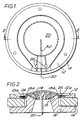
- the transducer is a tweeter incorporating a dome diaphragm supporting a voice coil which is supplied with the input signal.
- the tweeter comprises an annular top plate 12 of ferromagnetic material, a ring-shaped magnet 14 of ceramic material which does not conduct electricity, and an integral component of ferromagnetic material which defines a generally annular back plate 16 and a hollow pole piece 18.
- the pole piece 18 supports a phasing plug 19 (shown in Figure 2 only) of plastics, non electrically conducting material.
- Each of the top plate 12, the back plate 16 and the hollow pole piece 18 is a solid of revolution about the axis of the ring-shaped magnet 14, and each includes a radial slit 20 which ensures that the electrically conducting closed loop which would otherwise exist is interrupted.
- the width of the slit 20 need only be large enough to prevent circulation of electric current - typically 0.5 to 1mm, and is believed to have only a very minor influence on the magnetic field.
- the gap formed by the slit is preferably filled with a suitable non-conducting resin material.
- a dome diaphragm 22 is supported on the top plate 12 and carries a multi-turn voice coil 24 of fine wire which is located in the narrow annular gap defined between the inner periphery of the top plate 12 and the outer periphery of the pole piece 18.
- the terminals of the voice coil 24 are attached to two tags 26 at the edge of the diaphragm 22.
- the active, central part of the diaphragm 22 is formed of a thin sheet of metallic or non-metallic material. Since a metallic dome may also constitute a closed loop, a non-conducting sector 30 may be introduced into the diaphragm 22 if it is made of metal by replacing the metal material by a non-conducting sheet material of similar mechanical properties. Alternatively, the diaphragm 22 may be made of a material which does not conduct electricity.
- an input signal is applied to the two tags 26 and the voice coil moves in accordance with the current supplied. Because the top plate 12 and the integral pole piece 18 and back plate 16 include a discontinuity in the form of the slit 20, they cannot act as a single short-circuited coil.
- the diaphragm is generally cone shaped and supported at its outer edge by a flexible flange attached to one end of a metal support which is connected at its other end to the top plate 12.
- the metal support frame would ordinarily also define a closed, electrically conducting path which will be within the varying magnetic field generated in use.
- the metal support frame include a discontinuity such as a slit or a series of slits to break the electrical circuit otherwise defined by the support frame.
- the top plate may include an annular support plate or heat sink for heat generated in use. Again, the annular support plate should include one or more slits to prevent it defining a short-circuited loop within the influence of the varying magnetic field.
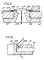
- FIG. 5 there is shown another example of a transducer incorporating features of this invention.
- the construction of the top plate 12, the ring-shaped magnet 14, the integral back plate 16 and hollow pole piece 18 are similar to those of the arrangement of Figures 1 to 4 and will not be described in detail again.
- the dome diaphragm 22 is of generally similar structure except that the voice coil 25 is in the form of a single, closed coil. It may, for example, simply be a cylinder of electrically conducting sheet material.
- the transducer is energised by means of a fixed coil 32 which surrounds the lower portion of the pole piece 18.
- a pole tip 18 a of the pole piece 18 and a pole tip 12 a of the front plate 12 are shown integral with the pole piece 18 and the front plate 12 respectively.
- the pole tip 18 a is shown to be tapered towards the air gap whereas the pole tip 12 a is parallel sided. Either tapered or parallel sided pole tips may be used for the front plate and pole piece as desired.
- Separate pole tips 18 a , 12 a may be provided and be attached to the pole piece 18 and the front plate 12 respectively if desired and as shown in Figure 6. If separate pole tips 18 a , 12 a are provided then they should be provided with a slit 20 to make them discontinuous.
- the pole tips if separate may be provided of a different material or of the same material as the pole piece 18 and the front plate 12, they could for example be provided of a material of different magnetic permeability and saturation.
Landscapes
- Physics & Mathematics (AREA)
- Engineering & Computer Science (AREA)
- Acoustics & Sound (AREA)
- Signal Processing (AREA)
- Audible-Bandwidth Dynamoelectric Transducers Other Than Pickups (AREA)
- Reciprocating, Oscillating Or Vibrating Motors (AREA)
Applications Claiming Priority (2)
| Application Number | Priority Date | Filing Date | Title |
|---|---|---|---|
| GB888809805A GB8809805D0 (en) | 1988-04-26 | 1988-04-26 | Electromagnetic transducer |
| GB8809805 | 1988-04-26 |
Publications (2)
| Publication Number | Publication Date |
|---|---|
| EP0339820A2 true EP0339820A2 (de) | 1989-11-02 |
| EP0339820A3 EP0339820A3 (de) | 1991-03-20 |
Family
ID=10635840
Family Applications (1)
| Application Number | Title | Priority Date | Filing Date |
|---|---|---|---|
| EP19890303509 Withdrawn EP0339820A3 (de) | 1988-04-26 | 1989-04-10 | Elektromagnetischer Wandler |
Country Status (4)
| Country | Link |
|---|---|
| EP (1) | EP0339820A3 (de) |
| JP (1) | JPH01318399A (de) |
| AU (1) | AU3301289A (de) |
| GB (1) | GB8809805D0 (de) |
Cited By (1)
| Publication number | Priority date | Publication date | Assignee | Title |
|---|---|---|---|---|
| EP0537705A3 (de) * | 1991-10-16 | 1994-03-23 | Lux Corp |
Families Citing this family (2)
| Publication number | Priority date | Publication date | Assignee | Title |
|---|---|---|---|---|
| JPH04103796U (ja) * | 1991-01-24 | 1992-09-07 | 株式会社ケンウツド | スピーカ用磁気回路およびそれに用いられるボイスコイル |
| JP4630319B2 (ja) * | 2007-09-10 | 2011-02-09 | 宏一 平岡 | ホーンスピーカ |
Family Cites Families (6)
| Publication number | Priority date | Publication date | Assignee | Title |
|---|---|---|---|---|
| NL61472C (de) * | 1938-05-04 | |||
| DE2131035A1 (de) * | 1971-06-23 | 1973-01-11 | Magnetfab Bonn Gmbh | Ringspalt-magnetsystem mit polen verminderter elektrischer leitfaehigkeit |
| US4293741A (en) * | 1979-06-21 | 1981-10-06 | Digre Clifford B | Magnet assembly |
| JPS5627600A (en) * | 1979-08-10 | 1981-03-17 | Kanenori Kishi | Magnetic circuit of moving coil type transducer |
| US4295011A (en) * | 1979-09-11 | 1981-10-13 | Epicure Products Inc. | Linear excursion-constant inductance loudspeaker |
| US5062140A (en) * | 1988-04-27 | 1991-10-29 | Sony Corporation | Induction speaker |
-
1988
- 1988-04-26 GB GB888809805A patent/GB8809805D0/en active Pending
-
1989
- 1989-04-10 EP EP19890303509 patent/EP0339820A3/de not_active Withdrawn
- 1989-04-13 AU AU33012/89A patent/AU3301289A/en not_active Abandoned
- 1989-04-24 JP JP10184489A patent/JPH01318399A/ja active Pending
Cited By (1)
| Publication number | Priority date | Publication date | Assignee | Title |
|---|---|---|---|---|
| EP0537705A3 (de) * | 1991-10-16 | 1994-03-23 | Lux Corp |
Also Published As
| Publication number | Publication date |
|---|---|
| JPH01318399A (ja) | 1989-12-22 |
| EP0339820A3 (de) | 1991-03-20 |
| AU3301289A (en) | 1989-11-02 |
| GB8809805D0 (en) | 1988-06-02 |
Similar Documents
| Publication | Publication Date | Title |
|---|---|---|
| US4531025A (en) | Loudspeaker with commutated coil drive | |
| EP0605400B1 (de) | Dynamischer Lautsprecher | |
| EP0422214B1 (de) | Selbstkühlender lautsprecher | |
| EP2719198B1 (de) | Electromechanischer-electroakustischer wandler mit geringer dicke und hoher auslenkung und entsprechendes herstellungsverfahren | |
| EP3550854A1 (de) | Lautsprecher mit doppelplattenstruktur | |
| EP3634013B1 (de) | Magnetsystem für einen elektromechanischen wandler | |
| US8542865B2 (en) | Transducer motor structure and inside-only voice coil for use in loudspeakers | |
| EP0486254B1 (de) | Dynamischer Lautsprecher mit niedriger Verzerrung | |
| US7706563B2 (en) | Concentric radial ring motor | |
| US4547632A (en) | Dynamic loudspeaker | |
| EP0891117B1 (de) | Lautsprecher und Tonwiedergabeanordnung mit einem solchen Lautsprecher | |
| US9282410B2 (en) | Transducer motor structure with enhanced flux | |
| US3358088A (en) | Electromechanical transducer | |
| CN113949973B (zh) | 一种振动特性优化平板耳机 | |
| US3935399A (en) | Loud speakers | |
| US7873180B2 (en) | Voice coil actuator | |
| EP0339820A2 (de) | Elektromagnetischer Wandler | |
| US5381483A (en) | Minimal inductance electrodynamic transducer | |
| US11290823B2 (en) | Double voice coil loudspeaker transducer unit | |
| JP3190189B2 (ja) | スピーカ | |
| WO1999030533A1 (en) | Electrodynamic acoustic transducer with reduced equivalent inductance of the moving parts | |
| EP4589993A1 (de) | Mehrspaltiger magnetischer motor zur verwendung in lautsprechern | |
| CN113557752A (zh) | 具有改善线性度的扬声器电机 | |
| US20060097583A1 (en) | Electromechanical transducers | |
| US20020122558A1 (en) | Magnetic circuit for an electrodynamic loudspeaker |
Legal Events
| Date | Code | Title | Description |
|---|---|---|---|
| PUAI | Public reference made under article 153(3) epc to a published international application that has entered the european phase |
Free format text: ORIGINAL CODE: 0009012 |
|
| AK | Designated contracting states |
Kind code of ref document: A2 Designated state(s): AT BE DE ES FR GB IT NL SE |
|
| PUAL | Search report despatched |
Free format text: ORIGINAL CODE: 0009013 |
|
| AK | Designated contracting states |
Kind code of ref document: A3 Designated state(s): AT BE DE ES FR GB IT NL SE |
|
| STAA | Information on the status of an ep patent application or granted ep patent |
Free format text: STATUS: THE APPLICATION IS DEEMED TO BE WITHDRAWN |
|
| 18D | Application deemed to be withdrawn |
Effective date: 19911103 |