EP0339692A2 - Verfahren zum Herstellen eines verschleissfesten Waffenlaufs - Google Patents
Verfahren zum Herstellen eines verschleissfesten Waffenlaufs Download PDFInfo
- Publication number
- EP0339692A2 EP0339692A2 EP89111458A EP89111458A EP0339692A2 EP 0339692 A2 EP0339692 A2 EP 0339692A2 EP 89111458 A EP89111458 A EP 89111458A EP 89111458 A EP89111458 A EP 89111458A EP 0339692 A2 EP0339692 A2 EP 0339692A2
- Authority
- EP
- European Patent Office
- Prior art keywords
- barrel
- liner
- mandrel
- gun
- metal
- Prior art date
- Legal status (The legal status is an assumption and is not a legal conclusion. Google has not performed a legal analysis and makes no representation as to the accuracy of the status listed.)
- Withdrawn
Links
Images

Classifications
-
- F—MECHANICAL ENGINEERING; LIGHTING; HEATING; WEAPONS; BLASTING
- F41—WEAPONS
- F41A—FUNCTIONAL FEATURES OR DETAILS COMMON TO BOTH SMALLARMS AND ORDNANCE, e.g. CANNONS; MOUNTINGS FOR SMALLARMS OR ORDNANCE
- F41A21/00—Barrels; Gun tubes; Muzzle attachments; Barrel mounting means
- F41A21/02—Composite barrels, i.e. barrels having multiple layers, e.g. of different materials
-
- C—CHEMISTRY; METALLURGY
- C23—COATING METALLIC MATERIAL; COATING MATERIAL WITH METALLIC MATERIAL; CHEMICAL SURFACE TREATMENT; DIFFUSION TREATMENT OF METALLIC MATERIAL; COATING BY VACUUM EVAPORATION, BY SPUTTERING, BY ION IMPLANTATION OR BY CHEMICAL VAPOUR DEPOSITION, IN GENERAL; INHIBITING CORROSION OF METALLIC MATERIAL OR INCRUSTATION IN GENERAL
- C23C—COATING METALLIC MATERIAL; COATING MATERIAL WITH METALLIC MATERIAL; SURFACE TREATMENT OF METALLIC MATERIAL BY DIFFUSION INTO THE SURFACE, BY CHEMICAL CONVERSION OR SUBSTITUTION; COATING BY VACUUM EVAPORATION, BY SPUTTERING, BY ION IMPLANTATION OR BY CHEMICAL VAPOUR DEPOSITION, IN GENERAL
- C23C4/00—Coating by spraying the coating material in the molten state, e.g. by flame, plasma or electric discharge
- C23C4/18—After-treatment
- C23C4/185—Separation of the coating from the substrate
Definitions
- the wear which occurs on the internal surface of a gun barrel as a projectile passes through and from the barrel is well known. Such wear and erosion of the surface of the barrel is due in part to the abrasion of the surface of the projectile against the internal wear surface of the gun barrel.
- the propellant and propellant gases may also cause abrasion, wear, chemical erosion and occasionally melting. Erosion by melting may be aggravated by the so called “blow by" phenomenon in which extremely high velocity gas passes between portions of the projectile and the wall of the barrel as the projectile is accelerated along the length of the barrel and projected from the muzzle.
- the mode of failure of structures designed for specific end uses such as gun barrels can be determined by basic mechanisms.
- One such mechanism is the rate at which heat can be transferred from a surface which receives the heat through the structure to a surface which can dissipate the heat.
- the heat is received by the barrel at the barrel interior due to the burning and heat of burning of the propellant material.
- frictional force of the projectile moving along and against the surface of the interior of the barrel can generate heat at the immediate surface contacted by the projectile.
- the gun barrel may fail either locally at the inner surface of the gun barrel by localized melting or metal deformation at high temperature or the physical properties of the overall structure of the barrel may deteriorate resulting in a rupture.
- Another mode of failure is the simple mechanical failure to contain the mechanical forces which are applied on the gun barrel.
- a propellant is ignited and burns it generates not only heat but also very high pressure and this pressure must be mechanically contained by the barrel.
- the rifling on the barrel mechanically applies a torsional force to the projectile to give it spin necessary to aid it in its accurate flight to a destination or target.
- mechanical failure of the barrel can occur at the location adjacent to the chamber where the barrel rifling starts.
- the combined barrel and propellant must be treated as a system because all the elements of the gun must be kept in balance. Any one element which is out of balance with the others can cause failure. For example, if the propellant generates excessive pressure or temperature or is used in excessive amount, this alone could disrupt the balance between the several components of the system and lead to excessive heat and thermal degradation of the barrel or bore surface.
- One object of the present invention is to form an improved gun barrel capable of withstanding higher temperature and related gun operating conditions.
- Another object is to form a gun barrel capable of withstanding higher rates of fire, both intermittent and sustained.
- Another object is to form a gun barrel suitable for use with higher energy propellants.
- Another object is to form a barrel capable of longer term sustained firing operation.
- Another object is to form a gun barrel capable of longer term efficient and effective service.
- a gun barrel by plasma spray deposition onto a preformed mandrel to have a refractory inner liner and a gun barrel outer jacket formed over the inner liner with an intimate bond therebetween.
- the present invention relates to low pressure vacuum plasma spray formation of gun barrels.
- a low pressure plasma deposition process results in rapid solidification plasma deposition of the deposited material to form a layer. Such deposition has typically resulted, at its center, in a layer density which is greater than 97% of the theoretical density of the deposited material. Further, the level of contamination in the deposited material is quite low.
- the arc plasma spray process has been used during the past 25 years to apply coatings to a variety of substrates for applications such as wear resistance and corrosion resistance.
- conventional plasma spray processing usually is done in air. Coatings so applied are characterized by porosity ranging typically in the 5% to 25% range, and high oxide content. Such plasma spray process is simply unsuitable for use in practice of the present invention.
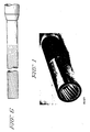
- the mandrel on which a gun barrel may be formed pursuant to the present invention is illustrated in Figure 2 and may be of a metal such as copper or other high melting point material adapted to be formed with external ribs.
- the mandrel has external rifling ribs 10 formed on its outer surface 12 so that a barrel liner which is formed on the mandrel will have conforming internal rifling grooves. Such grooves are seen as the light inner shaped layer at the end of the plasma formed gun barrel section of Figure 1. After formation of the barrel on the mandrel the mandrel is removed as discussed below.
- the mandrel may also include a larger end 14 over which the chamber of the barrel is formed.
- the chamber and the rifled portion are sized so that a subsequent densification by heating will yield barrels with correct final dimensions.
- the rifling ribs are formed on the exterior of the mandrel and such manufacturing process is relatively simple compared with the conventional gun rifling operation.
- the axial twist of the ribs can be given any desired shapes or curves.
- One form of rib which is particularly preferred is the rib with the accelerated pitch illustrated in Figures 2 and 6.
- the pitch of the rifling may be changed to give the projectile an increased component of torque and to increase the angular acceleration of the projectile itself.
- a mandrel having a surface of ribbing adapted to provide one form of rifling which results in accelerated rotation, or gain twist, of a projectile in a gun barrel formed on the mandrel.
- the first ribbing 16 beyond chamber 24 is axially aligned so that no torque is applied as a projectile contacts complementary axially aligned rifling in a barrel.
- the pitch of the ribs on the mandrel relative to the barrel axis, and the pitch of the resultant rifling in a barrel formed on the mandrel is increased as illustrated at 18 further down the barrel from the chamber 14.
- the pitch may be held constant, as at 20, and for the remainder of the length of the barrel.
- the present method makes formation of complex rifling patterns in a barrel efficient and economical because the rifling is formed as external lands and grooves on an easy-to-work mandrel rather than in the internal surface of a difficult to work actual gun barrel.
- a refractory material such as metal or ceramic or a combination of ceramic and metal
- the deposition of a refractory material, such as metal or ceramic or a combination of ceramic and metal, onto the mandrel of Figure 2 to form an inner liner for a gun barrel is carried through the use of vacuum plasma deposition techniques as taught in Patent 3,839,618.
- the thickness of the liner is carefully designed to minimize the use of more expensive and critical materials.
- a plasma gun which delivers the molten powder is moved relative to the workpiece so that the coating on the mandrel is formed with a significant measure of radial uniformity around the barrel.
- the deposit is preferably varied in thickness to place higher or greater thickness of the liner material at the portions of the barrel where the greatest wear and greatest heating occur.
- a thicker layer is formed at the exit of the chamber and also at the start of the rifling. Also a greater thickness is preferably formed at the muzzle of the bore as there is a tendency for a flattening of the rifling lands at this end as the projectile exits from the muzzle end.
- an intermediate layer may be formed over the liner to provide a transition in properties between the properties of the liner and those of the jacket metal which forms the major bulk of the barrel.
- the intermediate layer may be formed by mixing the powder used in forming the liner with the powder of the jacket metal.
- the liner is formed as illustrated in Figure 2 and the intermediate layer is formed on top of the liner as illustrated in Figure 3 with no interruption in the forming process.
- This permits good bonding to be achieved between layers.
- This also permits the productivity to be maintained at an elevated level. Further it permits maintenance of the barrel temperature at a level preferred for the deposit of the molten metal particles from the plasma and permits a very strong integral bond approaching theoretical strength to be formed between the outer surface of the liner and the intermediate layer.
- Figure 4 the mandrel with an overlain liner and an intermediate layer overlaying the liner is displayed partly in elevation and partly in section.
- Intermediate layer 24 reveals less definition of the ribs 10 than layer 22 of Figure 3, or the ribs themselves 10 of Figure 2.
- Three layers 26, 28 and 30 are illustrated in the portion of Figure 4 illustrated in section. Actually the two inner layers 28 and 30 are less distinct and may appear as a part of the liner layer 26.
- Figure 5 which is a vertical section along the axis of the bore of the barrel there is illustrated in semi-schematic fashion the composite inner liner plus the intermediate layer, as a single layer, as they fit inside the outer metal jacket as part of the barrel structure of this invention.
- the finished barrel article is illustrated in vertical section in Figure 5 and provides a novel gun barrel which has a number of advantages as follows.
- the refractory metal liner prevents the melting of the bore surface in the breech end and elsewhere along the barrel. This location 30 is where the highest temperature is developed as the propellant burns in the cartridge and is expelled from the cartridge opening 32 into the breech end 30 of the barrel.
- the enlarged breech 34 is not excessively heated but is subjected to high forces requiring a high modulus of elasticity as the propellant in the cartridge expands.
- the bore surface is a refractory material, including a metal such as tantalum, tungsten, molybdenum, or the like, metal or ceramics such as carbides, oxides or similar compounds of refractory or other metals, such refractory surface can withstand heating and thermal shock at very elevated temperatures without incipient melting. Because the metal of the liner is at the higher temperatures which can be tolerated by refractory materials there is a much higher thermal driving force driving the heat from the liner surface through the barrel metal to the barrel exterior.
- the outer barrel surface can be at a higher temperature, and accordingly release more heat to its environment, than conventional barrels without causing damages, such as are described above, to the interior surfaces of the barrel. Consequently the composite gun barrel can sustain higher flame temperatures and meet the requirements of a structural integrity of a high performance gun barrel.
- this composite barrel prevents the wear of the barrel further down particularly as the metal of the rifling starts to apply force and rotary motion to the projectile as it advances through the bore.
- This composite construction has the effect of lessening the wear.
- the very effective control of the rifling in the bore and at the muzzle and the ability to tailor the rifling so that it undergoes a change in pitch along the length the development of high wear at portion of the bore where the rifling starts is reduced.
- the incorporation of the refractory metals into the composite structure improves the barrel inasmuch as they retain their physical properties at higher temperatures and this resistance to high temperature wear further influences a reduction in the wear at this portion of the bore.
- a further advantage is in lessening and preventing the flattening of the rifling particularly in the area proximate the chamber and muzzle.
- Special tailoring of the pitch of the rifling proximate the bore as in forming the mandrel of Figure 1 or Figure 2 is similarly feasible.
- the use of the liner of this invention with the refractory metal and with the extremely good metallurgical bond both between the refractory metal and the intermediate layer, and between the intermediate layer and the solid metal jacket provides a greater resistance on the part of these components to wear.
- a key advantage of this invention is to provide a combination of a highly wear resistant material bonded through an intermediate layer to a high strength metal jacket to yield a near net product.
- the materials which are used for fabrication of the liner of the present invention are high melting temperature materials and these can include the following: tantalum alloys, such as, Ta-10W (Ta-10 w/o W) or T-111 (Ta-8W-2Hf); columbium base alloys (C-129Y); chromium, tungsten base, molybdenum base alloys (TZM); and the platinum group alloys.
- the materials also include the non-metal refractory materials such as carbides, oxides, borides as well as cermets and combinations of metals and non-metal refractories.
- the present method permits the addition of compounds such as carbides, oxides and borides which can be included in the powder from which the various layers of the product of the present invention can be formed.
- the very inner surface of the liner may be entirely oxide, carbide or boride, grading to a refractory metal.
- the mandrel onto which the refractory liner is plasma deposited can be smooth for those barrels which fire fin stabilized projectiles.
- a smooth bore barrel can be formed for later machining to form internal rifling.
- some of the advantages of the present invention are lost if the thin layer of the refractory metal is first formed on the interior of the barrel and this surface is then machined at a later date after the mandrel has been removed.
- the interface layer between the liner and the jacket is preferably made to have a gradual transition in properties between those of the refractory material of the liner and those of the metal of the jacket and to ensure a sound metallurgical bond between the layers.
- the gradual transition in properties can be important in making the backup properties of the outer jacket available to the liner of the barrel inasmuch as the disruptive forces caused by propellant burning and projectile movement are delivered to the barrel at the liner.
- the external jacket of the gun barrel which provides the needed strength and rigidity for the barrel is also vacuum plasma formed.
- the jacket can be sprayed to near net shape and to include metal for various clamps and mounting mechanism by controlling the number of plasma spray passes. This control can be exercised by developing a program for the relative movement of the plasma gun and the mandrel as the barrel layers are formed and deposited on the mandrel.
- the jacket itself can be plasma sprayed from conventional small arms steel alloys containing chromium, molybdenum and vanadium or from large caliber barrel type steels such as the AISI 4340 steels.
- a black corrosion protection coating can be applied over the jacket for barrels which do not require external machining as for example where there are clamping surfaces which must be formed with close tolerances.
- the black surface assists in heat radiation to improve barrel cooling and also to provide limited corrosion protection.
- the voids can be reduced or eliminated by secondary treatments of the barrel.
- One such treatment involves heating the barrel to an elevated temperature for a time which consolidates the metal of the barrel.
- hot gas isostatic pressing may be employed.
- hot forging may be used to consolidate the barrel following its spray formation.
- the mandrel is mechanically removed or dissolved chemically to leave a finished inner refractory surface to be used as the inner surface of the barrel liner.
- a heat treatment to provide desirable mechanical properties may be applied to the liner and to the jacket following the removal of the mandrel. Such heat treatment can impart improvements to the combined barrel structure and enhance its properties.
- Finish machining may be required for certain barrels particularly to facilitate the mounting of the barrel into some other mechanical mechanism.
- the metal of the transition layer is a composition of refractory metal of the refractory layer and the jacket metal of the jacket layer. It may have a lower proportion of the more expensive refractory metal and the proportion of the refractory and jacket metal may vary through the thickness of the transition layer. Ratios of 90% refractory metal and 10% jacket metal to 10% refractory metal and 90% jacket metal are useful. A concentration gradient may be, and preferably is formed in the intermediate layer extending from the liner to the jacket.
- the thickness of the refractory metal liner may be smaller where higher ratios of refractory metal are employed in the intermediate layer.
- the composite structure is formed with the three intimately bonded layers and all three layers may be formed using only two distinct powders to be fed to the plasma gun.
- One powder is the refractory metal powder and the other is the jacket metal powder.
- the barrel may be formed in one continuous plasma spray session starting with the refractory metal, to deposit the liner over the length of the mandrel, then by switching to a powder mix of refractory and jacket metal powders to form the intermediate layer, and by then switching to a powder entirely made up of jacket metal.
- a higher thickness of liner metal may be deposited around the chamber end of the mandrel or around the portion of the mandrel where the greater stress is to be developed based on the design of the barrel and the use to be made of it.
- a greater liner thickness may be formed at the section of the barrel where the projectile first meets the rifling if the rifling design is one which develops great stress in this section.
- Abrasion and wear down of rifling at the muzzle can be lessened by increasing the liner thickness at this section of the barrel.
- the inner liner may have a thickness of between 0.25 to 0.50 mm
- the intermediate layer may have a thickness of 0.25 to 0.50mm
- the jacket may have a thickness ranging from about 1 centimeter to about 2 centimeters.
Landscapes
- Engineering & Computer Science (AREA)
- Chemical & Material Sciences (AREA)
- Physics & Mathematics (AREA)
- Plasma & Fusion (AREA)
- Chemical Kinetics & Catalysis (AREA)
- Materials Engineering (AREA)
- Mechanical Engineering (AREA)
- Metallurgy (AREA)
- Organic Chemistry (AREA)
- General Engineering & Computer Science (AREA)
- Coating By Spraying Or Casting (AREA)
- Other Surface Treatments For Metallic Materials (AREA)
Applications Claiming Priority (2)
| Application Number | Priority Date | Filing Date | Title |
|---|---|---|---|
| US606110 | 1984-05-02 | ||
| US06/606,110 US4577431A (en) | 1984-05-02 | 1984-05-02 | Wear resistant gun barrel and method of forming |
Related Parent Applications (2)
| Application Number | Title | Priority Date | Filing Date |
|---|---|---|---|
| EP85902359.0 Division | 1985-04-29 | ||
| EP85902359A Division EP0179877B1 (de) | 1984-05-02 | 1985-04-29 | Verschliessfester waffenlauf sowie verfahren zu seiner herstellung |
Publications (2)
| Publication Number | Publication Date |
|---|---|
| EP0339692A2 true EP0339692A2 (de) | 1989-11-02 |
| EP0339692A3 EP0339692A3 (de) | 1990-01-31 |
Family
ID=24426576
Family Applications (2)
| Application Number | Title | Priority Date | Filing Date |
|---|---|---|---|
| EP89111458A Withdrawn EP0339692A3 (de) | 1984-05-02 | 1985-04-29 | Verfahren zum Herstellen eines verschleissfesten Waffenlaufs |
| EP85902359A Expired - Lifetime EP0179877B1 (de) | 1984-05-02 | 1985-04-29 | Verschliessfester waffenlauf sowie verfahren zu seiner herstellung |
Family Applications After (1)
| Application Number | Title | Priority Date | Filing Date |
|---|---|---|---|
| EP85902359A Expired - Lifetime EP0179877B1 (de) | 1984-05-02 | 1985-04-29 | Verschliessfester waffenlauf sowie verfahren zu seiner herstellung |
Country Status (6)
| Country | Link |
|---|---|
| US (1) | US4577431A (de) |
| EP (2) | EP0339692A3 (de) |
| JP (1) | JPH063359B2 (de) |
| DE (1) | DE3582222D1 (de) |
| IL (1) | IL75023A (de) |
| WO (1) | WO1985005173A1 (de) |
Cited By (5)
| Publication number | Priority date | Publication date | Assignee | Title |
|---|---|---|---|---|
| EP0602877A1 (de) * | 1992-12-14 | 1994-06-22 | General Electric Company | Aus mehreren Schichten bestehendes Verbundrohr für eine Waffe |
| DE4443854A1 (de) * | 1994-12-09 | 1996-06-13 | Thyssen Industrie | Verfahren zum Herstellen von Rohren oder rohrartigen Formköpern aus einem Refraktär-Metall, insbesondere aus Molybdän |
| WO2000058043A1 (en) * | 1999-03-15 | 2000-10-05 | Damasteel Aktiebolag | Blank for gunbarrel, method for producing said gunbarrel and gunbarrel |
| WO2001088218A1 (de) * | 2000-05-15 | 2001-11-22 | Euromat Gesellschaft Für Werkstofftechnologie Und Transfer Mbh | Verfahren zum aufbringen einer schicht aus edelmetall und/oder einer edelmetalllegierung sowie deren verwendung |
| EP1715080A1 (de) * | 2005-04-21 | 2006-10-25 | Rheinmetall W & M GmbH | Waffenrohr und Verfahren zur Beschichtung der inneren Oberfläche des Waffenrohres |
Families Citing this family (25)
| Publication number | Priority date | Publication date | Assignee | Title |
|---|---|---|---|---|
| DE3513892A1 (de) * | 1985-04-17 | 1986-10-23 | Plasmainvent AG, Zug | Cr(pfeil abwaerts)2(pfeil abwaerts)o(pfeil abwaerts)3(pfeil abwaerts)-schutzschicht und verfahren zu deren herstellung |
| US4805833A (en) * | 1987-02-25 | 1989-02-21 | General Electric Company | Method of forming compacts with integral consolidation containers |
| US5312650A (en) * | 1988-01-12 | 1994-05-17 | Howmet Corporation | Method of forming a composite article by metal spraying |
| US5928799A (en) * | 1995-06-14 | 1999-07-27 | Ultramet | High temperature, high pressure, erosion and corrosion resistant composite structure |
| GB2320034B (en) * | 1996-11-08 | 1998-11-11 | Monitor Coatings & Eng | Coating of continuous casting machine grid plates |
| CA2211961C (en) | 1997-07-29 | 2001-02-27 | Pyrogenesis Inc. | Near net-shape vps formed multilayered combustion system components and method of forming the same |
| US6482248B1 (en) | 2000-11-28 | 2002-11-19 | Magnum Research, Inc. | Aluminum composite for gun barrels |
| US6594936B1 (en) * | 2002-10-03 | 2003-07-22 | Gary Sniezak | Method for lining a gun barrel |
| US20040140292A1 (en) * | 2002-10-21 | 2004-07-22 | Kelley John E. | Micro-welded gun barrel coatings |
| US7721478B2 (en) * | 2004-04-27 | 2010-05-25 | Materials & Electrochemical Research Corp. | Gun barrel and method of forming |
| US7493691B2 (en) * | 2004-05-20 | 2009-02-24 | Honeywell International Inc. | Co-molding metallic-lined phenolic components |
| US8112930B2 (en) * | 2005-01-27 | 2012-02-14 | Ra Brands, L.L.C. | Firearm with enhanced corrosion and wear resistance properties |
| US7934332B2 (en) * | 2006-02-23 | 2011-05-03 | Sturm, Ruger & Company, Inc. | Composite firearm barrel |
| US7921590B2 (en) | 2006-02-23 | 2011-04-12 | Strum, Ruger & Company, Inc. | Composite firearm barrel reinforcement |
| US20070256345A1 (en) | 2006-05-04 | 2007-11-08 | Hall David R | A Rigid Composite Structure with a Superhard Interior Surface |
| US7882883B2 (en) * | 2007-08-06 | 2011-02-08 | Anderson Kenneth K | Method for making a barrel front for a paintball marker |
| US20100080982A1 (en) * | 2008-10-01 | 2010-04-01 | Caterpillar Inc. | Thermal spray coating application |
| US9695489B1 (en) | 2013-01-14 | 2017-07-04 | Gunwright Intellectual Property Llc | Gun barrel manufacturing methods |
| US9186712B1 (en) | 2013-01-14 | 2015-11-17 | David W. Wright | Gun barrel manufacturing methods |
| US9365930B1 (en) | 2013-01-14 | 2016-06-14 | David W. Wright | Gun barrel manufacturing methods |
| US9546837B1 (en) | 2015-10-09 | 2017-01-17 | Bh5773 Ltd | Advanced gun barrel |
| US11060194B2 (en) | 2016-12-21 | 2021-07-13 | The United States Of America, As Represented By The Secretary Of The Navy | Methods for producing composite structures using diffusion or thermal reactions of a plurality of layers |
| USD874600S1 (en) * | 2017-01-11 | 2020-02-04 | Palmetto State Armory, LLC | Gun barrel end |
| WO2021030801A1 (en) * | 2019-08-15 | 2021-02-18 | Vista Outdoor Operations Llc | Devices and methods for extraction of high pressure cartridge casings |
| SE2300011A1 (sv) * | 2023-02-09 | 2024-08-10 | Bae Systems Bofors Ab | Eldrör |
Family Cites Families (23)
| Publication number | Priority date | Publication date | Assignee | Title |
|---|---|---|---|---|
| US311539A (en) * | 1885-02-03 | Button-hook | ||
| US2104319A (en) * | 1934-02-10 | 1938-01-04 | Remington Arms Co Inc | Manufacture of rifled tubes |
| US2395044A (en) * | 1942-04-02 | 1946-02-19 | Walter T Gorton | Gun |
| US2792657A (en) * | 1946-05-16 | 1957-05-21 | Battelle Development Corp | Gun barrel coated with tantalum |
| US2799959A (en) * | 1947-06-11 | 1957-07-23 | Elburt F Osborn | Nitrided gun barrel with chromium deposit |
| US2981155A (en) * | 1953-03-04 | 1961-04-25 | Parlanti Conrad Authony | Composite gun barrels |
| BE557981A (de) * | 1953-03-24 | |||
| US3156040A (en) * | 1960-11-08 | 1964-11-10 | Bell Aerospace Corp | Metal fabrication |
| US3112539A (en) * | 1960-11-17 | 1963-12-03 | Gen Motors Corp | Forming articles by arc plasma spraying |
| US3427185A (en) * | 1964-02-19 | 1969-02-11 | United Aircraft Corp | Composite structural material incorporating metallic filaments in a matrix,and method of manufacture |
| US3427698A (en) * | 1965-11-26 | 1969-02-18 | Chandler Evans Inc | Rocket nozzle |
| US3740522A (en) * | 1971-04-12 | 1973-06-19 | Geotel Inc | Plasma torch, and electrode means therefor |
| US3914573A (en) * | 1971-05-17 | 1975-10-21 | Geotel Inc | Coating heat softened particles by projection in a plasma stream of Mach 1 to Mach 3 velocity |
| US3717914A (en) * | 1971-06-24 | 1973-02-27 | Union Carbide Corp | Reusable mandrel for structures having zero draft or re-entrant geometries |
| US3823302A (en) * | 1972-01-03 | 1974-07-09 | Geotel Inc | Apparatus and method for plasma spraying |
| US3839618A (en) * | 1972-01-03 | 1974-10-01 | Geotel Inc | Method and apparatus for effecting high-energy dynamic coating of substrates |
| DE2320371A1 (de) * | 1973-04-21 | 1974-11-07 | Celamerck Gmbh & Co Kg | Thiophosphonsaeureester |
| CH602237A5 (de) * | 1974-12-23 | 1978-07-31 | Bbc Brown Boveri & Cie | |
| BE878999A (fr) * | 1979-09-26 | 1980-03-26 | Herstal Sa | Canon composite et procede pour sa fabrication |
| US4328257A (en) * | 1979-11-26 | 1982-05-04 | Electro-Plasma, Inc. | System and method for plasma coating |
| US4371563A (en) * | 1980-03-27 | 1983-02-01 | Electro-Plasma, Inc. | Fine particle filter system having low pressure drop for gaseous flow systems |
| US4391860A (en) * | 1981-01-21 | 1983-07-05 | Eutectic Corporation | Device for the controlled feeding of powder material |
| JP5012237B2 (ja) | 2007-06-13 | 2012-08-29 | パナソニック株式会社 | 洗濯機およびそのプログラム |
-
1984
- 1984-05-02 US US06/606,110 patent/US4577431A/en not_active Expired - Fee Related
-
1985
- 1985-04-26 IL IL75023A patent/IL75023A/xx unknown
- 1985-04-29 EP EP89111458A patent/EP0339692A3/de not_active Withdrawn
- 1985-04-29 DE DE8585902359T patent/DE3582222D1/de not_active Expired - Lifetime
- 1985-04-29 WO PCT/US1985/000756 patent/WO1985005173A1/en not_active Ceased
- 1985-04-29 EP EP85902359A patent/EP0179877B1/de not_active Expired - Lifetime
- 1985-04-29 JP JP60502007A patent/JPH063359B2/ja not_active Expired - Lifetime
Cited By (9)
| Publication number | Priority date | Publication date | Assignee | Title |
|---|---|---|---|---|
| EP0602877A1 (de) * | 1992-12-14 | 1994-06-22 | General Electric Company | Aus mehreren Schichten bestehendes Verbundrohr für eine Waffe |
| TR28217A (tr) * | 1992-12-14 | 1996-02-29 | Gen Electric | Cok-tabakali kompozit top namlusu. |
| DE4443854A1 (de) * | 1994-12-09 | 1996-06-13 | Thyssen Industrie | Verfahren zum Herstellen von Rohren oder rohrartigen Formköpern aus einem Refraktär-Metall, insbesondere aus Molybdän |
| WO2000058043A1 (en) * | 1999-03-15 | 2000-10-05 | Damasteel Aktiebolag | Blank for gunbarrel, method for producing said gunbarrel and gunbarrel |
| JP2002540374A (ja) * | 1999-03-15 | 2002-11-26 | ダマスチール アクチボラグ | 銃身のためのブランクと、そして該銃身を製造するための方法およびその銃身 |
| US6564689B1 (en) | 1999-03-15 | 2003-05-20 | Damasteel Aktiebolag | Blank for gun barrel, method for producing said gun barrel and gun barrel |
| CN1332774C (zh) * | 1999-03-15 | 2007-08-22 | 达玛斯蒂尔股份公司 | 用于枪筒的坯料、用于生产所述枪筒的方法以及该枪筒 |
| WO2001088218A1 (de) * | 2000-05-15 | 2001-11-22 | Euromat Gesellschaft Für Werkstofftechnologie Und Transfer Mbh | Verfahren zum aufbringen einer schicht aus edelmetall und/oder einer edelmetalllegierung sowie deren verwendung |
| EP1715080A1 (de) * | 2005-04-21 | 2006-10-25 | Rheinmetall W & M GmbH | Waffenrohr und Verfahren zur Beschichtung der inneren Oberfläche des Waffenrohres |
Also Published As
| Publication number | Publication date |
|---|---|
| WO1985005173A1 (en) | 1985-11-21 |
| JPH063359B2 (ja) | 1994-01-12 |
| IL75023A (en) | 1992-08-18 |
| JPS61502069A (ja) | 1986-09-18 |
| EP0179877B1 (de) | 1991-03-20 |
| EP0339692A3 (de) | 1990-01-31 |
| US4577431A (en) | 1986-03-25 |
| DE3582222D1 (de) | 1991-04-25 |
| EP0179877A4 (de) | 1987-02-12 |
| EP0179877A1 (de) | 1986-05-07 |
Similar Documents
| Publication | Publication Date | Title |
|---|---|---|
| US4577431A (en) | Wear resistant gun barrel and method of forming | |
| EP0201557B1 (de) | Gewehrlauf zur verwendung bei hohen temperaturen | |
| EP1740899B1 (de) | Waffenlauf und herstellungsverfahren | |
| US5935351A (en) | Method for making a high temperature, high pressure, erosion and corrosion resistant composite structure | |
| US7278353B2 (en) | Reactive shaped charges and thermal spray methods of making same | |
| US10281227B1 (en) | Cold spray and WAAM methods for manufacturing gun barrels | |
| US20040140292A1 (en) | Micro-welded gun barrel coatings | |
| US4409881A (en) | Composite barrel and process for the manufacture thereof | |
| CN1332774C (zh) | 用于枪筒的坯料、用于生产所述枪筒的方法以及该枪筒 | |
| US6511710B2 (en) | Method of internally coating a weapon barrel by a plasma flame | |
| US2990342A (en) | Method of making a gun barrel | |
| RU2557892C2 (ru) | Способ изготовления ствола оружия | |
| US4797985A (en) | Method of applying a metallic guide band to a thin-walled projectile body | |
| US20040052964A1 (en) | Method for coating the inside of a gun barrel | |
| US7743965B2 (en) | Process to deposit a protective coating on the inner wall of a tube, and notably a gun barrel produced according to this process | |
| EP4662453A1 (de) | Fass sowie verfahren zur herstellung von fasssegmenten und verfahren zur herstellung eines fasses und einer einen fass aufweisenden abschussvorrichtung | |
| US4381319A (en) | Method of bonding rotating bands on projectiles | |
| US5096507A (en) | Method of applying a cerium misch metal coating to the surface of a splinter-active component of an incendiary splinter projectile | |
| WO2024232797A1 (en) | Breech block for a cannon and method for the manufacturing of a breech block for a cannon | |
| WO2025239814A1 (en) | Method of stretching and arranging film and film stretching machine | |
| WO2024205466A1 (en) | Breech block for a firing device and method for the manufacturing of a breech block for a cannon | |
| Mansford | Surface coatings 4—Sprayed coatings | |
| WO2025250064A1 (en) | Barrels, methods of manufacturing barrels and barrel segments and launching device comprising barrels | |
| O'Shea et al. | GUN BARREL EROSION IN SMALL CALIBER WEAPONS |
Legal Events
| Date | Code | Title | Description |
|---|---|---|---|
| PUAI | Public reference made under article 153(3) epc to a published international application that has entered the european phase |
Free format text: ORIGINAL CODE: 0009012 |
|
| 17P | Request for examination filed |
Effective date: 19890623 |
|
| AC | Divisional application: reference to earlier application |
Ref document number: 179877 Country of ref document: EP |
|
| AK | Designated contracting states |
Kind code of ref document: A2 Designated state(s): BE CH DE FR GB LI SE |
|
| PUAL | Search report despatched |
Free format text: ORIGINAL CODE: 0009013 |
|
| AK | Designated contracting states |
Kind code of ref document: A3 Designated state(s): BE CH DE FR GB LI SE |
|
| 17Q | First examination report despatched |
Effective date: 19920103 |
|
| STAA | Information on the status of an ep patent application or granted ep patent |
Free format text: STATUS: THE APPLICATION IS DEEMED TO BE WITHDRAWN |
|
| 18D | Application deemed to be withdrawn |
Effective date: 19920514 |