EP0339301A1 - Verfahren zur Bestimmung und Abschätzung der Notabschaltreserve eines Druckwasserkernreaktors - Google Patents
Verfahren zur Bestimmung und Abschätzung der Notabschaltreserve eines Druckwasserkernreaktors Download PDFInfo
- Publication number
- EP0339301A1 EP0339301A1 EP89105803A EP89105803A EP0339301A1 EP 0339301 A1 EP0339301 A1 EP 0339301A1 EP 89105803 A EP89105803 A EP 89105803A EP 89105803 A EP89105803 A EP 89105803A EP 0339301 A1 EP0339301 A1 EP 0339301A1
- Authority
- EP
- European Patent Office
- Prior art keywords
- power
- reactor
- reactivity
- measured
- core
- Prior art date
- Legal status (The legal status is an assumption and is not a legal conclusion. Google has not performed a legal analysis and makes no representation as to the accuracy of the status listed.)
- Granted
Links
- 238000000034 method Methods 0.000 title claims abstract description 31
- XLYOFNOQVPJJNP-UHFFFAOYSA-N water Substances O XLYOFNOQVPJJNP-UHFFFAOYSA-N 0.000 title claims abstract description 27
- 230000009257 reactivity Effects 0.000 claims abstract description 37
- 238000003780 insertion Methods 0.000 claims abstract description 23
- 230000037431 insertion Effects 0.000 claims abstract description 23
- 238000009826 distribution Methods 0.000 claims abstract description 14
- ZOXJGFHDIHLPTG-UHFFFAOYSA-N Boron Chemical compound [B] ZOXJGFHDIHLPTG-UHFFFAOYSA-N 0.000 claims description 22
- 229910052796 boron Inorganic materials 0.000 claims description 22
- 230000000694 effects Effects 0.000 claims description 22
- 230000009471 action Effects 0.000 claims description 12
- 101100353161 Drosophila melanogaster prel gene Proteins 0.000 claims description 7
- 238000005259 measurement Methods 0.000 claims description 7
- 230000004907 flux Effects 0.000 claims description 6
- 230000009467 reduction Effects 0.000 claims description 4
- 239000000243 solution Substances 0.000 description 13
- 239000000446 fuel Substances 0.000 description 12
- 230000008569 process Effects 0.000 description 10
- 238000006243 chemical reaction Methods 0.000 description 8
- 238000002347 injection Methods 0.000 description 6
- 239000007924 injection Substances 0.000 description 6
- 230000007423 decrease Effects 0.000 description 5
- 238000004519 manufacturing process Methods 0.000 description 5
- 239000011159 matrix material Substances 0.000 description 5
- 239000011358 absorbing material Substances 0.000 description 4
- 230000000712 assembly Effects 0.000 description 4
- 238000000429 assembly Methods 0.000 description 4
- 230000033228 biological regulation Effects 0.000 description 4
- 238000001816 cooling Methods 0.000 description 3
- 230000004992 fission Effects 0.000 description 3
- 239000000463 material Substances 0.000 description 3
- 229910052724 xenon Inorganic materials 0.000 description 3
- FHNFHKCVQCLJFQ-UHFFFAOYSA-N xenon atom Chemical compound [Xe] FHNFHKCVQCLJFQ-UHFFFAOYSA-N 0.000 description 3
- 230000002745 absorbent Effects 0.000 description 2
- 239000002250 absorbent Substances 0.000 description 2
- 230000032683 aging Effects 0.000 description 2
- KGBXLFKZBHKPEV-UHFFFAOYSA-N boric acid Chemical compound OB(O)O KGBXLFKZBHKPEV-UHFFFAOYSA-N 0.000 description 2
- 239000004327 boric acid Substances 0.000 description 2
- 238000011161 development Methods 0.000 description 2
- 230000018109 developmental process Effects 0.000 description 2
- 230000005611 electricity Effects 0.000 description 2
- 238000011156 evaluation Methods 0.000 description 2
- 230000007774 longterm Effects 0.000 description 2
- 238000012544 monitoring process Methods 0.000 description 2
- 238000003860 storage Methods 0.000 description 2
- 230000001960 triggered effect Effects 0.000 description 2
- 230000002159 abnormal effect Effects 0.000 description 1
- 230000002411 adverse Effects 0.000 description 1
- 230000008859 change Effects 0.000 description 1
- 239000002826 coolant Substances 0.000 description 1
- 238000010790 dilution Methods 0.000 description 1
- 239000012895 dilution Substances 0.000 description 1
- 238000006073 displacement reaction Methods 0.000 description 1
- 239000012530 fluid Substances 0.000 description 1
- 230000009931 harmful effect Effects 0.000 description 1
- 239000013529 heat transfer fluid Substances 0.000 description 1
- 230000003449 preventive effect Effects 0.000 description 1
- 230000002441 reversible effect Effects 0.000 description 1
- 239000000523 sample Substances 0.000 description 1
- 230000035945 sensitivity Effects 0.000 description 1
- 238000012546 transfer Methods 0.000 description 1
- 230000007704 transition Effects 0.000 description 1
- 239000013598 vector Substances 0.000 description 1
Images
Classifications
-
- G—PHYSICS
- G21—NUCLEAR PHYSICS; NUCLEAR ENGINEERING
- G21D—NUCLEAR POWER PLANT
- G21D3/00—Control of nuclear power plant
- G21D3/08—Regulation of any parameters in the plant
- G21D3/12—Regulation of any parameters in the plant by adjustment of the reactor in response only to changes in engine demand
- G21D3/16—Varying reactivity
-
- G—PHYSICS
- G21—NUCLEAR PHYSICS; NUCLEAR ENGINEERING
- G21C—NUCLEAR REACTORS
- G21C7/00—Control of nuclear reaction
- G21C7/36—Control circuits
-
- G—PHYSICS
- G21—NUCLEAR PHYSICS; NUCLEAR ENGINEERING
- G21C—NUCLEAR REACTORS
- G21C17/00—Monitoring; Testing ; Maintaining
- G21C17/10—Structural combination of fuel element, control rod, reactor core, or moderator structure with sensitive instruments, e.g. for measuring radioactivity, strain
- G21C17/104—Measuring reactivity
-
- G—PHYSICS
- G21—NUCLEAR PHYSICS; NUCLEAR ENGINEERING
- G21C—NUCLEAR REACTORS
- G21C7/00—Control of nuclear reaction
-
- G—PHYSICS
- G21—NUCLEAR PHYSICS; NUCLEAR ENGINEERING
- G21D—NUCLEAR POWER PLANT
- G21D3/00—Control of nuclear power plant
- G21D3/04—Safety arrangements
-
- Y—GENERAL TAGGING OF NEW TECHNOLOGICAL DEVELOPMENTS; GENERAL TAGGING OF CROSS-SECTIONAL TECHNOLOGIES SPANNING OVER SEVERAL SECTIONS OF THE IPC; TECHNICAL SUBJECTS COVERED BY FORMER USPC CROSS-REFERENCE ART COLLECTIONS [XRACs] AND DIGESTS
- Y02—TECHNOLOGIES OR APPLICATIONS FOR MITIGATION OR ADAPTATION AGAINST CLIMATE CHANGE
- Y02E—REDUCTION OF GREENHOUSE GAS [GHG] EMISSIONS, RELATED TO ENERGY GENERATION, TRANSMISSION OR DISTRIBUTION
- Y02E30/00—Energy generation of nuclear origin
- Y02E30/30—Nuclear fission reactors
Definitions
- the present invention relates to the control of electro-nuclear pressurized water power stations and, more particularly, the determination and evaluation of the emergency stop margin of the reactor of such a power station. More specifically, it aims to assess the emergency stop margin, which takes account of the accidental loss of secondary circuit steam preventively.
- Pressurized water nuclear power plants are well known. Briefly, they include a reactor containing, in a tank, fuel assemblies formed by fuel rods containing the fissile material; in some of them there are movable rods or control rods containing a neutron absorbing material.
- the fuel rod control rods ordered together, form a control cluster.
- the fuel assemblies are immersed in pressurized water which circulates in a primary circuit having several primary loops each including a primary pump and a steam generator. One of these loops also includes a pressurizer maintaining the water pressure in the reactor.
- the pressurized water serves as a moderating and heat transfer fluid. In addition, it contains boron in solution, a neutron absorbing material used, as well as control clusters, to control the operation of the reactor.
- the steam generators supply steam to a secondary circuit essentially comprising a turbine driving an alternator, a condenser and pumps.
- Reactivity is a measure of the evolution of the chain reaction at the heart of the reactor.
- the neutrons produced by the fission of heavy nuclei slowed down by the moderator which is the pressurized water of the primary circuit, more or less absorbed by the control rods and the boron in solution, come in turn cause new fissions.
- the factor, called k by which the number of fissions is multiplied from one generation to the next is generally equal to 1. It can be temporarily greater than 1.
- the positive deviation of k from 1 is called reactivity. It is calculated in cfm (parts per hundred thousand). In the presence of a non-zero reactivity, the chain reaction tends to increase. At other times, the factor k may be less than 1, the reactivity is negative and we then speak of anti-reactivity. In this case, the reaction tends to suffocate.
- the power of the reactor is adjusted by action on the reactivity, in fact by action on the position of the control rods and / or on the boron concentration.
- the reaction is growing.
- the reactor then stabilizes at an increased power level. To decrease the power, we operate in reverse.
- the reactor can thus supply the thermal power which is required of it, generally to meet the electricity needs of the network to which the power station is coupled.
- the control of the thermal power supplied by the reactor to meet the needs of the electrical network is thus preferably carried out by the control rods.
- the insertion of the control rods adversely affects the axial distribution of the power produced in the reactor. This results in temperature inequalities in the reactor core, with, in particular, accelerated wear of the fuel at the hottest places and localized production of xenon, factors intervening in a restrictive manner in the procedure of piloting the reactor and imposing a correlative recourse to action on the level of boron in solution.
- the secondary circuit is suddenly cooled.
- the safety devices are triggered and cause the total insertion of all the control clusters and an injection of safety boron. It normally follows the shutdown of the reactor.
- the level boron solution may be relatively small, while insertion of control rods may be relatively large.
- the complete insertion of the control rods provides sufficient anti-reactivity to stop the release of thermal power in the reactor.
- This effect combined with the cooling of the primary circuit caused by the rupture of the secondary circuit, causes a significant drop in water temperature in the reactor core, therefore an increase in its efficiency as a moderator and a corresponding contribution of reactivity.
- this contribution of reactivity could outweigh the anti-reactivity provided by the complete insertion of the control bars and the reaction would resume, temporarily, which could then lead to , briefly, at an unacceptable rise in the temperature of the fuel elements.
- This process essentially consists in monitoring the anti-reactivity that the R group can provide at any time. Indeed, we can consider that the contribution power control clusters is zero, until fully inserted. They do provide anti-reactivity, but the corresponding decrease in moderator temperature brings reactivity of the same value. Furthermore, the contribution in this regard of security bars is known.
- the R group clusters alone, are in a continuously variable position, which does not depend on the temperature ; their position is therefore the only parameter to monitor. It should be added that the assessment must take into account, in the sense of safety, all the inaccuracies of the driving process, in particular with regard to the anti-reactivity effect of the power control rods.
- the required anti-reactivity is thus increased by a security term of a constant value, defined by approximation, to cover the most unfavorable conditions.
- the anti-reactivity that can be provided by temperature control bars is only an estimated value, derived from the position of the bars and from a relationship between the position of the bars and the anti-reactivity, in the most case unfavorable from the point of view of safety.
- the present invention therefore relates to a process for determining the emergency stop margin in pressurized water reactors which is suitable for the operating process considered second and even, more generally, for any operating process.
- the method for determining the emergency stop margin applied includes an approximation of unmeasured influences, in the form of a security term increasing the required anti-reactivity and another approximation. as to the anti-reactivity that can be provided at any time by the temperature regulation bars. This often results in undue restrictions in piloting the reactor.
- the invention also relates to a method for determining the emergency stop margin which does not suffer from such restrictions.
- the term DC can be a sum comprising one or more of the following terms: - a first term DP corresponding to the reactivity effect of the power reduction compared to the nominal power, which is a function of the first degree the axial distortion of measured power, - a first corrective term FP corresponding to the reactivity effect of the error at real power, as measured, caused by the distortion of the density distribution of the water in the reactor core, which is a second degree function of the axial power distortion measured, a second corrective term FT corresponding to the reactivity effect of the difference between the average temperature of the core, which is a measured quantity, and the set temperature, which is a preset quantity.
- the method of the invention also provides for determining the difference between the emergency stop margin thus calculated and a minimum margin calculated once and for all for the reactor and considered as a constant, which is included in the constant EGo.
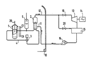
- FIG. 1 the core of a pressurized water reactor is represented at 1, associated in a primary circuit 4 with a steam generator 2.
- the movement of pressurized water is forced by a primary pump 3.
- a pressurizer 5 maintains the volume and pressure of the water in the primary circuit.
- These various elements are arranged in an enclosure 10 crossed by the conduits of a secondary circuit 12 connected to the steam generator 2.
- This secondary circuit 12 comprises a turbine 13, driving an alternator 14, a condenser 15 and a pump. secondary 16.
- Valves 19 and 20 allow the bypass of the turbine 13, to maintain the secondary circuit in a case where the drive of the alternator must be interrupted.
- the reactor core contains, in a tank, fuel assemblies formed by fuel rods containing the fissile material; in some of them there are movable rods or control rods 20 containing a neutron absorbing material.
- the fuel rod control rods ordered together, form a control cluster.
- the fuel assemblies are immersed in the pressurized water which circulates in the primary circuit 4, which in fact has several primary loops of which only one, that which is represented in the figure includes the pressurizer 5.
- the pressurized water serves as fluid moderator and coolant.
- it contains boron in solution, a neutron absorbing material used, as well as control clusters, to control the operation of the reactor.
- the figure indicates, in C1 to C6, ionization chambers placed near the reactor, outside the tank, for measuring the neutron flux at different height levels.
- these detectors are composed of four individual detectors per level, the output signals of which are combined to each provide a signal representative of the instantaneous power emitted by the reactor at the corresponding level.
- devices have not been shown for measuring and determining various variables such as the temperature at various locations in the primary circuit, the insertion depth of the control bars, the content boron water under pressure in the primary circuit, etc.
- the state of the reactor core is periodically redefined, by placing the reactor under determined operating conditions and then performing specific measurements, some of which use probes introduced into the core on this occasion.
- the actual power of the Prel reactor is expressed as a fraction of the nominal power, that is to say the maximum power expected in normal operation of the reactor, for which the insertion of the bars of control is minimal.
- the real power is measured, for example, from the neutron fluxes indicated by the detectors C1 to C6.
- the axial power distortion that is to say a value characterizing the asymmetry of the real power distribution, will also be derived from the output signals of these detectors.
- the position of the control bars is indicated directly by cluster insertion step counters.
- a reference temperature Tref is defined as a function of the power requested from the reactor.
- An average core temperature Tmoy is derived from the temperatures measured in the primary circuit, at the entry of pressurized water into the reactor and at its outlet.
- the invention relates to a method for determining and evaluating the emergency stop margin for such a reactor, in a normal operating situation, which takes preventive account of the loss of steam from the secondary circuit 12.
- ⁇ Pp is the reactivity (positive) provided by a change from nominal power to zero power
- - ⁇ Pg total anti-reactivity of the control rods, including the power control clusters and safety stop clusters, is a previously determined characteristic of the reactor, in which we consider, for safety, that a cluster of maximum anti-reactivity does not come in insertion
- - ⁇ Pp total reactivity due to the cooling of the water under pressure to the temperature which corresponds to the stopping of the reaction is also a previously determined characteristic of the reactor
- - ⁇ Pr anti-reactivity consumed by the inserted control rods, therefore depending on the actual operating conditions of the reactor.
- - EGo is a constant.
- EG corresponds to the anti-reactivity consumed by the insertion of the bars and is determined from the power measurement signals of the neutron flux detectors and the insertion levels of the power control clusters.
- the term EG results from the application of the following formula, in matrix notation: in which [Pref] and [Pr] are vectors representing an axial power distribution, the first periodically redefined in a reference configuration, in order to represent the axial exhaustion of the heart, while the second follows from online measurements carried out by neutron flux detectors.
- [P] [T] ⁇ 1 [S] ⁇ 1 [I] in which [P] is the axial power distribution, [T] is a transfer matrix of the measurement system, [S] is a detector sensitivity matrix and [I] represents the outputs of neutron detectors.
- the invention further provides by evaluating the contribution of reactivity due to the power difference between the nominal power and the current situation of the reactor, in the form of a DC term. To get as close as possible to the reactivity value already consumed, the invention provides for this term a sum comprising one or more of the terms DP, FP, FT defined below.
- EGo can be a simple constant of scale.
- This constant can however include a minimum margin calculated once and for all for the reactor and considered as a constant, which is the margin allowing to deal with the consequences of a break in the secondary circuit. Then, in this case, the evaluation of the determined margin is simple, it is enough that it is greater than zero.
- the invention also provides for the use of the emergency stop margin thus determined and evaluated for triggering, by any means of a corrective action consisting in raising the level of boron in solution in the primary circuit.
Landscapes
- Physics & Mathematics (AREA)
- Engineering & Computer Science (AREA)
- Plasma & Fusion (AREA)
- General Engineering & Computer Science (AREA)
- High Energy & Nuclear Physics (AREA)
- Chemical & Material Sciences (AREA)
- Chemical Kinetics & Catalysis (AREA)
- Business, Economics & Management (AREA)
- Emergency Management (AREA)
- Monitoring And Testing Of Nuclear Reactors (AREA)
Applications Claiming Priority (2)
| Application Number | Priority Date | Filing Date | Title |
|---|---|---|---|
| FR8804439 | 1988-04-05 | ||
| FR8804439A FR2629623B1 (fr) | 1988-04-05 | 1988-04-05 | Procede de determination et d'evaluation de la marge d'arret d'urgence d'un reacteur nucleaire a eau pressurisee |
Publications (2)
| Publication Number | Publication Date |
|---|---|
| EP0339301A1 true EP0339301A1 (de) | 1989-11-02 |
| EP0339301B1 EP0339301B1 (de) | 1993-05-26 |
Family
ID=9364940
Family Applications (1)
| Application Number | Title | Priority Date | Filing Date |
|---|---|---|---|
| EP89105803A Expired - Lifetime EP0339301B1 (de) | 1988-04-05 | 1989-04-03 | Verfahren zur Bestimmung und Abschätzung der Notabschaltreserve eines Druckwasserkernreaktors |
Country Status (8)
| Country | Link |
|---|---|
| US (1) | US5032346A (de) |
| EP (1) | EP0339301B1 (de) |
| JP (1) | JPH0213892A (de) |
| KR (1) | KR0148481B1 (de) |
| CA (1) | CA1300765C (de) |
| DE (1) | DE68906714T2 (de) |
| ES (1) | ES2041362T3 (de) |
| FR (1) | FR2629623B1 (de) |
Cited By (2)
| Publication number | Priority date | Publication date | Assignee | Title |
|---|---|---|---|---|
| FR2949899A1 (fr) * | 2009-09-10 | 2011-03-11 | Commissariat Energie Atomique | Dispositif de mesure de reactivite |
| RU2543501C1 (ru) * | 2013-11-22 | 2015-03-10 | Николай Александрович Виногоров | Способ определения эффективности рабочего органа системы управления и защиты ядерного реактора |
Families Citing this family (9)
| Publication number | Priority date | Publication date | Assignee | Title |
|---|---|---|---|---|
| DE19837235C1 (de) * | 1998-08-17 | 2000-01-27 | Nsm Ag | Vorrichtung zum Umschlagen von einzelnen zu einem Stapel zusammengefaßten Tafeln |
| KR100598037B1 (ko) * | 2004-11-08 | 2006-07-06 | 한국수력원자력 주식회사 | 동적 제어봉 제어능 측정방법 |
| CN100492547C (zh) * | 2005-06-18 | 2009-05-27 | 蔡光明 | 反应堆反应性测量方法 |
| RU2312374C2 (ru) * | 2005-11-30 | 2007-12-10 | Федеральное государственное унитарное предприятие "Центральный научно-исследовательский институт им. акад. А.Н. Крылова" (ФГУП "ЦНИИ им. акад. А.Н. Крылова") | Способ градуировки канала измерения плотности нейтронного потока в ядерном реакторе в абсолютных единицах мощности |
| JP5364424B2 (ja) * | 2009-04-14 | 2013-12-11 | 三菱重工業株式会社 | 原子炉 |
| EP2281785A1 (de) * | 2009-08-06 | 2011-02-09 | AGC Glass Europe | Glasschmelzofen |
| US11227697B2 (en) * | 2018-10-29 | 2022-01-18 | Framatome Inc. | Self-powered in-core detector arrangement for measuring flux in a nuclear reactor core |
| CN109979625B (zh) * | 2019-03-28 | 2022-02-18 | 江苏核电有限公司 | 一种测量反应堆堆芯增殖特性对称性的试验方法 |
| CN116487084B (zh) * | 2023-04-21 | 2026-03-13 | 中广核研究院有限公司 | 核电厂运行保护方法、装置、计算机设备和存储介质 |
Citations (5)
| Publication number | Priority date | Publication date | Assignee | Title |
|---|---|---|---|---|
| GB1018012A (en) * | 1963-03-05 | 1966-01-26 | Atomic Energy Commission | Method of determining the negative reactivity of subcritical nuclear multiplying systems |
| FR2349922A1 (fr) * | 1976-04-28 | 1977-11-25 | Combustion Eng | Procede de reduction rapide de la puissance d'un reacteur nucleaire |
| EP0051542A2 (de) * | 1980-11-03 | 1982-05-12 | Framatome Sa | Verfahren zum Betrieb eines Kernreaktors durch Verstellen von Regelstabgruppen im Reaktorkern. |
| EP0108265A2 (de) * | 1982-10-18 | 1984-05-16 | INTERATOM Gesellschaft mit beschränkter Haftung | Verfahren und Vorrichtung zur Überwachung der Reaktivitätsbilanz des Core eines Kernreaktors und zur Diagnose von Reaktivitätsstörungen |
| EP0238299A2 (de) * | 1986-03-19 | 1987-09-23 | Westinghouse Electric Corporation | Eichung eines Parametervorausberechnungsgerätes für die Spaltzone eines Kernreaktors |
Family Cites Families (1)
| Publication number | Priority date | Publication date | Assignee | Title |
|---|---|---|---|---|
| JPS5316192A (en) * | 1976-07-29 | 1978-02-14 | Hitachi Ltd | Operation controlling method in reactor |
-
1988
- 1988-04-05 FR FR8804439A patent/FR2629623B1/fr not_active Expired - Lifetime
-
1989
- 1989-03-31 CA CA000595388A patent/CA1300765C/fr not_active Expired - Lifetime
- 1989-04-03 DE DE89105803T patent/DE68906714T2/de not_active Expired - Fee Related
- 1989-04-03 ES ES198989105803T patent/ES2041362T3/es not_active Expired - Lifetime
- 1989-04-03 EP EP89105803A patent/EP0339301B1/de not_active Expired - Lifetime
- 1989-04-04 KR KR1019890004435A patent/KR0148481B1/ko not_active Expired - Fee Related
- 1989-04-05 JP JP1086698A patent/JPH0213892A/ja active Pending
- 1989-04-05 US US07/333,409 patent/US5032346A/en not_active Expired - Lifetime
Patent Citations (5)
| Publication number | Priority date | Publication date | Assignee | Title |
|---|---|---|---|---|
| GB1018012A (en) * | 1963-03-05 | 1966-01-26 | Atomic Energy Commission | Method of determining the negative reactivity of subcritical nuclear multiplying systems |
| FR2349922A1 (fr) * | 1976-04-28 | 1977-11-25 | Combustion Eng | Procede de reduction rapide de la puissance d'un reacteur nucleaire |
| EP0051542A2 (de) * | 1980-11-03 | 1982-05-12 | Framatome Sa | Verfahren zum Betrieb eines Kernreaktors durch Verstellen von Regelstabgruppen im Reaktorkern. |
| EP0108265A2 (de) * | 1982-10-18 | 1984-05-16 | INTERATOM Gesellschaft mit beschränkter Haftung | Verfahren und Vorrichtung zur Überwachung der Reaktivitätsbilanz des Core eines Kernreaktors und zur Diagnose von Reaktivitätsstörungen |
| EP0238299A2 (de) * | 1986-03-19 | 1987-09-23 | Westinghouse Electric Corporation | Eichung eines Parametervorausberechnungsgerätes für die Spaltzone eines Kernreaktors |
Non-Patent Citations (1)
| Title |
|---|
| PATENT ABSTRACTS OF JAPAN, vol. 2, no. 57 (M-78)[684], 25 avril 1978, page 684 M 78; & JP-A-53 16 192 (HITACHI SEISAKUSHO K.K.) 14-02-1978 * |
Cited By (2)
| Publication number | Priority date | Publication date | Assignee | Title |
|---|---|---|---|---|
| FR2949899A1 (fr) * | 2009-09-10 | 2011-03-11 | Commissariat Energie Atomique | Dispositif de mesure de reactivite |
| RU2543501C1 (ru) * | 2013-11-22 | 2015-03-10 | Николай Александрович Виногоров | Способ определения эффективности рабочего органа системы управления и защиты ядерного реактора |
Also Published As
| Publication number | Publication date |
|---|---|
| JPH0213892A (ja) | 1990-01-18 |
| KR890016580A (ko) | 1989-11-29 |
| CA1300765C (fr) | 1992-05-12 |
| ES2041362T3 (es) | 1993-11-16 |
| KR0148481B1 (ko) | 1998-12-15 |
| EP0339301B1 (de) | 1993-05-26 |
| US5032346A (en) | 1991-07-16 |
| FR2629623A1 (fr) | 1989-10-06 |
| DE68906714T2 (de) | 1993-12-02 |
| FR2629623B1 (fr) | 1990-11-16 |
| DE68906714D1 (de) | 1993-07-01 |
Similar Documents
| Publication | Publication Date | Title |
|---|---|---|
| EP0336338B1 (de) | Verfahren zur Bestimmung und Abschätzung des Leistungsbeaufschlagungsvermögens eines Druckwasserkernreaktors | |
| EP0339301B1 (de) | Verfahren zur Bestimmung und Abschätzung der Notabschaltreserve eines Druckwasserkernreaktors | |
| EP2218078B1 (de) | Verfahren zur ermittlung des zahlenwertes einer die steuerbarkeit eines kernreaktors repräsentierenden kenngrösse | |
| US4075059A (en) | Reactor power reduction system and method | |
| KR101577095B1 (ko) | 미임계 반응도 측정 방법 | |
| EP0369865B1 (de) | Verfahren zur Regelung eines Druckwasserkernreaktors | |
| EP0006040B1 (de) | Verfahren zur Regelung des Wasserstandes in Dampfkesseln oder Dampferzeugern | |
| FR2493582A1 (fr) | Procede de conduite d'un reacteur nucleaire par deplacement, dans le coeur de ce reacteur, de groupes de barres de commande | |
| EP3850643B1 (de) | Verfahren zum schutz eines kernreaktors und entsprechender kernreaktor | |
| EP3724591A1 (de) | Verfahren zur beurteilung der verschmutzung eines wärmetauschers | |
| FR2529706A1 (fr) | Procede pour regler le fonctionnement d'un generateur d'electricite fonctionnant a l'energie nucleaire et pour faire l'interface entre ce generateur et un reseau de distribution | |
| EP0406075B1 (de) | Verfahren für die Berechnung der Leistungsverteilung im Kern eines Kernkraftreaktors und Verfahren zum Kalibrieren der umgebenden Neutronendetektoren des Kerns eines Kernkraftreaktors | |
| FR3075449A1 (fr) | Procede de determination d'au moins une valeur limite d'au moins un parametre de fonctionnement d'un reacteur nucleaire, programme d'ordinateur et systeme electronique associes | |
| EP0127532A1 (de) | Verfahren und Vorrichtung zur Lokalisierung eines Fehlers der Leistungsverteilung in einem Druckwasserkernreaktor | |
| US4486381A (en) | Power controlling apparatus for boiling water atomic reactor | |
| EP0094884B1 (de) | Verfahren und Vorrichtung zur Regelung des pH-Wertes des Kühlwassers eines Druckwasserkernreaktors | |
| WO2019020836A1 (fr) | Procédé de surveillance d'un coeur nucléaire comprenant une relaxation d'un seuil, programme, support et réacteur nucléaire associés | |
| EP0281805A1 (de) | Methode zur Feststellung eines Stabeinfalles in einem Kernreaktor und Kernkraftwerk mit Schutz gegen solche Störungen | |
| CA2781998A1 (fr) | Procede et dispositif de detection de chute de grappe d'un reacteur nucleaire | |
| Hossain et al. | Design and Simulation of an Automatic Control Rod Position Controller System Incorporating Temperature and Xenon Poisoning Feedback for BAEC TRIGA Mark II Research Reactor | |
| CN119786084A (zh) | 钠冷快堆升降功率过程中预防反应堆意外短周期保护停堆的运行控制方法 | |
| Wray et al. | Control of SGHWRs | |
| Collett et al. | Control and transient performance of the dresden nucl ear power station | |
| DeHart et al. | Assessment of TRITON and PARCS for full-core MOX fuel calculations | |
| Choi et al. | LOCA power pulse analysis for CANDU-6 CANFLEX core |
Legal Events
| Date | Code | Title | Description |
|---|---|---|---|
| PUAI | Public reference made under article 153(3) epc to a published international application that has entered the european phase |
Free format text: ORIGINAL CODE: 0009012 |
|
| AK | Designated contracting states |
Kind code of ref document: A1 Designated state(s): BE CH DE ES GB IT LI SE |
|
| 17P | Request for examination filed |
Effective date: 19900502 |
|
| 17Q | First examination report despatched |
Effective date: 19920818 |
|
| GRAA | (expected) grant |
Free format text: ORIGINAL CODE: 0009210 |
|
| AK | Designated contracting states |
Kind code of ref document: B1 Designated state(s): BE CH DE ES GB IT LI SE |
|
| PG25 | Lapsed in a contracting state [announced via postgrant information from national office to epo] |
Ref country code: IT Free format text: LAPSE BECAUSE OF FAILURE TO SUBMIT A TRANSLATION OF THE DESCRIPTION OR TO PAY THE FEE WITHIN THE PRE;WARNING: LAPSES OF ITALIAN PATENTS WITH EFFECTIVE DATE BEFORE 2007 MAY HAVE OCCURRED AT ANY TIME BEFORE 2007. THE CORRECT EFFECTIVE DATE MAY BE DIFFERENT FROM THE ONE RECORDED.SCRIBED TIME-LIMIT Effective date: 19930526 |
|
| GBT | Gb: translation of ep patent filed (gb section 77(6)(a)/1977) |
Effective date: 19930601 |
|
| REF | Corresponds to: |
Ref document number: 68906714 Country of ref document: DE Date of ref document: 19930701 |
|
| REG | Reference to a national code |
Ref country code: ES Ref legal event code: FG2A Ref document number: 2041362 Country of ref document: ES Kind code of ref document: T3 |
|
| PLBE | No opposition filed within time limit |
Free format text: ORIGINAL CODE: 0009261 |
|
| STAA | Information on the status of an ep patent application or granted ep patent |
Free format text: STATUS: NO OPPOSITION FILED WITHIN TIME LIMIT |
|
| 26N | No opposition filed | ||
| EAL | Se: european patent in force in sweden |
Ref document number: 89105803.4 |
|
| REG | Reference to a national code |
Ref country code: GB Ref legal event code: IF02 |
|
| PGFP | Annual fee paid to national office [announced via postgrant information from national office to epo] |
Ref country code: GB Payment date: 20060424 Year of fee payment: 18 |
|
| PGFP | Annual fee paid to national office [announced via postgrant information from national office to epo] |
Ref country code: ES Payment date: 20060426 Year of fee payment: 18 Ref country code: CH Payment date: 20060426 Year of fee payment: 18 Ref country code: SE Payment date: 20060426 Year of fee payment: 18 |
|
| PGFP | Annual fee paid to national office [announced via postgrant information from national office to epo] |
Ref country code: BE Payment date: 20060516 Year of fee payment: 18 |
|
| PGFP | Annual fee paid to national office [announced via postgrant information from national office to epo] |
Ref country code: DE Payment date: 20060531 Year of fee payment: 18 |
|
| REG | Reference to a national code |
Ref country code: CH Ref legal event code: PL |
|
| GBPC | Gb: european patent ceased through non-payment of renewal fee |
Effective date: 20070403 |
|
| BERE | Be: lapsed |
Owner name: *FRAMATOME Effective date: 20070430 |
|
| PG25 | Lapsed in a contracting state [announced via postgrant information from national office to epo] |
Ref country code: DE Free format text: LAPSE BECAUSE OF NON-PAYMENT OF DUE FEES Effective date: 20071101 |
|
| PG25 | Lapsed in a contracting state [announced via postgrant information from national office to epo] |
Ref country code: LI Free format text: LAPSE BECAUSE OF NON-PAYMENT OF DUE FEES Effective date: 20070430 Ref country code: CH Free format text: LAPSE BECAUSE OF NON-PAYMENT OF DUE FEES Effective date: 20070430 |
|
| PG25 | Lapsed in a contracting state [announced via postgrant information from national office to epo] |
Ref country code: BE Free format text: LAPSE BECAUSE OF NON-PAYMENT OF DUE FEES Effective date: 20070430 |
|
| PG25 | Lapsed in a contracting state [announced via postgrant information from national office to epo] |
Ref country code: GB Free format text: LAPSE BECAUSE OF NON-PAYMENT OF DUE FEES Effective date: 20070403 |
|
| PG25 | Lapsed in a contracting state [announced via postgrant information from national office to epo] |
Ref country code: SE Free format text: LAPSE BECAUSE OF NON-PAYMENT OF DUE FEES Effective date: 20070404 |
|
| REG | Reference to a national code |
Ref country code: ES Ref legal event code: FD2A Effective date: 20070404 |
|
| PG25 | Lapsed in a contracting state [announced via postgrant information from national office to epo] |
Ref country code: ES Free format text: LAPSE BECAUSE OF NON-PAYMENT OF DUE FEES Effective date: 20070404 |