EP0338835A2 - Scroll type compressor - Google Patents
Scroll type compressor Download PDFInfo
- Publication number
- EP0338835A2 EP0338835A2 EP89303944A EP89303944A EP0338835A2 EP 0338835 A2 EP0338835 A2 EP 0338835A2 EP 89303944 A EP89303944 A EP 89303944A EP 89303944 A EP89303944 A EP 89303944A EP 0338835 A2 EP0338835 A2 EP 0338835A2
- Authority
- EP
- European Patent Office
- Prior art keywords
- chamber
- scroll
- orbiting scroll
- compressor
- end plate
- Prior art date
- Legal status (The legal status is an assumption and is not a legal conclusion. Google has not performed a legal analysis and makes no representation as to the accuracy of the status listed.)
- Granted
Links
Images


Classifications
-
- F—MECHANICAL ENGINEERING; LIGHTING; HEATING; WEAPONS; BLASTING
- F04—POSITIVE - DISPLACEMENT MACHINES FOR LIQUIDS; PUMPS FOR LIQUIDS OR ELASTIC FLUIDS
- F04C—ROTARY-PISTON, OR OSCILLATING-PISTON, POSITIVE-DISPLACEMENT MACHINES FOR LIQUIDS; ROTARY-PISTON, OR OSCILLATING-PISTON, POSITIVE-DISPLACEMENT PUMPS
- F04C18/00—Rotary-piston pumps specially adapted for elastic fluids
- F04C18/02—Rotary-piston pumps specially adapted for elastic fluids of arcuate-engagement type, i.e. with circular translatory movement of co-operating members, each member having the same number of teeth or tooth-equivalents
- F04C18/0207—Rotary-piston pumps specially adapted for elastic fluids of arcuate-engagement type, i.e. with circular translatory movement of co-operating members, each member having the same number of teeth or tooth-equivalents both members having co-operating elements in spiral form
- F04C18/0215—Rotary-piston pumps specially adapted for elastic fluids of arcuate-engagement type, i.e. with circular translatory movement of co-operating members, each member having the same number of teeth or tooth-equivalents both members having co-operating elements in spiral form where only one member is moving
-
- F—MECHANICAL ENGINEERING; LIGHTING; HEATING; WEAPONS; BLASTING
- F04—POSITIVE - DISPLACEMENT MACHINES FOR LIQUIDS; PUMPS FOR LIQUIDS OR ELASTIC FLUIDS
- F04C—ROTARY-PISTON, OR OSCILLATING-PISTON, POSITIVE-DISPLACEMENT MACHINES FOR LIQUIDS; ROTARY-PISTON, OR OSCILLATING-PISTON, POSITIVE-DISPLACEMENT PUMPS
- F04C27/00—Sealing arrangements in rotary-piston pumps specially adapted for elastic fluids
- F04C27/005—Axial sealings for working fluid
-
- F—MECHANICAL ENGINEERING; LIGHTING; HEATING; WEAPONS; BLASTING
- F04—POSITIVE - DISPLACEMENT MACHINES FOR LIQUIDS; PUMPS FOR LIQUIDS OR ELASTIC FLUIDS
- F04C—ROTARY-PISTON, OR OSCILLATING-PISTON, POSITIVE-DISPLACEMENT MACHINES FOR LIQUIDS; ROTARY-PISTON, OR OSCILLATING-PISTON, POSITIVE-DISPLACEMENT PUMPS
- F04C23/00—Combinations of two or more pumps, each being of rotary-piston or oscillating-piston type, specially adapted for elastic fluids; Pumping installations specially adapted for elastic fluids; Multi-stage pumps specially adapted for elastic fluids
- F04C23/008—Hermetic pumps
Definitions
- This invention relates to a scroll type compressor, and more particularly, to an axial sealing mechanism between a pair of scroll members of the scroll type compressor.
- above-mentioned scroll type compressor includes fixed scroll 10 having circular end plate 11 from which spiral element 12 extends and orbiting scroll 20 having circular end plate 21 from which spiral element 22 extends.
- Block member 30 is attached to circular end plate 11 by a plurality of fastening member, such as bolts 31, to define chamber 40 in which orbiting scroll 20 is disposed.
- Spiral elements 12 and 22 are interfitted at an angular and radial offset to make a plurality of line contacts to define at least one pair of sealed-off pockets.
- Driving mechanism 50 including rotatably supported drive shaft 51 is connected to orbiting scroll 20 to effect the orbital motion of orbiting scroll 20.
- Oldham coupling 60 is disposed between circular end plate 21 and block member 30 to prevent the rotation of orbiting scroll 20 during its orbital motion.
- Circular end plate 21 of orbiting scroll 20 divides chamber 40 into first chamber 41 in which spiral elements 12 and 22 exists and second chamber 42 in which Oldham coupling 60 and one end of driving mechanism 50 exists.
- Discharge port 70 is formed at a central portion of circular end plate 11 to discharge the compressed fluid from a central merged fluid pocket.
- Suction port 80 is formed at a peripheral portion of circular end plate 11 to be sucked suction fluid into the radial outermost fluid pockets.
- a pair of apertures 90 having throttling effect are formed at a middle portion of circular end plate 21 of orbiting scroll 20 to link second chamber 42 to a pair of intermediately compressed fluid pockets 41a respectively.
- intermediate fluid pockets 41a faces aperture 90
- pressure in intermediate fluid pockets 41a is changed in a some range.
- pressure in second chamber 42 is maintained an average pressure of the some range by throttling effect of aperture 90. Accordingly, orbiting scroll 20 is urged to fixed scroll 10 in virtue of averaged intermediate pressure in second chamber 42 to obtain a good axial seal therebetween.
- second chamber 42 admits the intermediately compressed fluid from intermediate fluid pocket 41a in which pressure changes in the some range. Therefore, fluctuation of pressure in second chamber 42 can not be avoided, even in the stable condition of operation of the compressor.
- Oldham coupling 60 and driving mechanism 50 intermittently undesirably receive a thrust force which is generated by a reaction force of compressed fluid in all of fluid pockets, thereby durability of the compressor is reduced.
- a machining process for forming aperature 90 at circular end plate 21 is required being precise.
- an end plate of an orbiting scroll is urged to a fixed scroll by a constant axial force.
- a scroll type compressor includes a fixed scroll having a first end plate from which a first spiral element extends and an orbital scroll having a second end plate from which a second spiral element extends.
- a block member is attached to the first end plate to define a chamber in which the orbiting scroll is disposed
- the first and second spiral elements interfit at an angular and radial off set to make a plurality of line contacts to define at least one pair of sealed-off fluid pockets.
- a first hollow portion for admitting discharged compressive fluid from a central merged fluid pockets is define in the compressor.
- a second hollow portion for admitting suction fluid sucked into radial outermost fluid pockets is defined in the compressor.
- a driving mechanism including a rotatable drive shaft is connected to the orbiting scroll to effect the orbital motion of the orbiting scroll.
- a rotation-preventing mechanism for preventing the rotation of the orbiting scroll during its orbital motion is disposed between the block member and the second end plate. The volume of the fluid pockets is changed by the orbital motion of the orbiting scroll.
- the second end plate of the orbiting scroll divides the chamber into a first chamber in which the first and second spiral elements exist and a second chamber in which the rotation-preventing mechanism and one end of the drive shaft exist.
- a first throttled conduit links the second chamber to the first hollow portion.
- a second throttled conduit links the second chamber to the second hollow portion.
- FIG. 2 A first embodiment of the present invention applied to a scroll type compressor for use a refrigerant circuit is illustrated in Figure 2, in which the same numerals are used to denote the corresponding elements shown in Figure 1 and the explanation of those elements is omitted.
- the bolts as a fastening members for fixedly attaching block member 30 to circular end plate 11 are not shown.
- drive shaft 51 rotatably penetrates hole 31 which is centrally formed at block member 30 through plain bearing 52 disposed between an outer peripheral surface of drive shaft 51 and an inner peripheral surface of hole 31.
- One end of drive shaft 51 is fixedly attached to bushing 53 disposed within second chamber 42.
- Circular boss 23 projecting from an end surface surface opposite to spiral element 22 is rotatably inserted into a circular depression 531 of which center is radially off set a center of drive shaft 51 through bearing 231.
- Aperature 71 having a throttling effect includes first aperture 71a and second aperture 71b.
- First aperture 71a is radially formed at circular end plate 11 to radially penetrate from an outer peripheral surface of circular end plate 11 to an inner peripheral wall of discharge port 70.
- Second aperture 71b is axially formed at circular end plate 11 to connect first aperture 71a to second chamber 42.
- Plug member 72 is fixedly attached to the outer peripheral surface of circular end plate 11 to close an outer radial end of first aperture 71a. Accordingly, aperture 71 links discharge port 70 to second chamber 42.
- Aperture 81 having a throttling effect includes third aperture 81a and fourth aperture 81b.
- Third aperture 81a is radially formed at block member 30 to radially penetrate from an outer peripheral surface of block member 30 to an inner peripheral surface of block member 30.
- Fourth aperture 81b is axially formed at block member 30 to connect third aperture 81a to second chamber 42.
- Plug member 82 is fixedly attached to the outer peripheral surface of block member 30 to close an outer radial end of third aperture 81a. Accordingly, aperture 81 links suction port 80 to second chamber 42.
- pressure in second chamber 42 can be selected by changing a diameter of both apertures 71 and 81. Still furthermore, Reduction of compression ability of the compressor due to blown-by discharge gas through aperture 71, second chamber 42 and aperture 81 can be largely decreased in virtue of the throttling effect of both aperture 71 and 81.
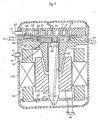
- FIG. 3 illustrates a second embodiment of the present invention applied to a hermetic type scroll compressor for use a refrigerating circuit.
- the same numerals are used to denote the corresponding elements shown in Figure 2 and the explanation of those elements is omitted.
- above-mentioned elements such as, fixed scroll 10, orbiting scroll 20, block member 30, driving mechanism 50 and Oldham coupling 60 are housed in hermetically sealed casing 100.
- Casing 100 further houses motor 54 for rotating drive shaft 51.
- Motor 54 includes Ring-shaped stator 54a and ring-shaped rotor 54b.
- Stator 54a is firmly secured to an inner peripheral wall of casing 100 by forcible insertion.
- Rotor 54b is firmly secured to drive shaft 51 by also forcibly insertion.
- Hole 511 is formed in drive shaft 51 to lead a lubricating oil 55 collected in a bottom of casing 100 to a gap between an outer peripheral surface of drive shaft 51 and an inner peripheral surface of plain bearing 52.
- inlet port 83 which radially and hermetically penetrates casing 100 is hermetically connected to suction port 80.
- One end of outlet port 73 which also radially and hermetically penetrates casing 100 is opened to inner space 101 of casing 100 to a gap between an outer peripheral surface of drive shaft 51 and an inner peripheral surface of plain bearing 52.
- Aperture 711 having throttling effect is formed at block member 30 to connect second chamber 42 to inner space 101 of casing 100.
- Aperture 811 having throttling effect is also formed at block member 30 to connect suction port 80 to second chamber 42.
- Aperture 811 includes apertures 811a and 811b these which are radially and axially formed at block member 30 respectively.
- suction gas in suction port 80 flowing from one element of a refrigerating circuit, such as an evaporator (not shown), through inlet port 83 is taken into the outermost fluid pockets and compressed in virtue of the orbital motion of orbiting scroll 20 and then discharged through discharge port 70.
- the discharged refrigerant gas is filled in inner space 101 of casing 100 except chamber 40, therefore this type of hermetic scroll compressor is generally called a high pressure type hermetic scroll compressor. Then a small part of the discharged refrigerant gas flows into second chamber 42 through aperture 711 with pressure decreasing.
- Figure 4 illustrates a third embodiment of the present invention also applied to a hermetic type scroll compressor for use a refrigerating circuit.
- inlet port 83′ which radially and hermetically penetrates casing 100 is opened to inner space 101 of casing 100 with being adjacent to suction port 80.
- outlet port 73′ which axially and hermetically penetrates casing 100 is hermetically connected to discharge port 70.
- Aperture 712 having throttling effect is formed at circular end plate 11 to connect discharge port 70 to second chamber 42.
- Aperture 712 includes aperture 712a and 712b these which are radially and axially formed at circular end plate 11 respectively.
- Aperture 812 having throttling effect is formed at block member 30 to connect second chamber 42 to inner space 101 of casing 100.
- suction gas in suction port 80 flowing from a element of a refrigerating circuit, such as an evaporator (not shown), through inlet port 83′ is taken into the outermost fluid pockets and compressed in virtue of the orbital motion of orbiting scroll 20 and then discharged through discharge port 70.
- a small part of the discharged refrigerant gas flows into second chamber 42 through aperture 712 with pressure decreasing.
- the present invention is applied to a hermetic type scroll compressor, but can be alternated with an open type scroll compressor.
Landscapes
- Engineering & Computer Science (AREA)
- Mechanical Engineering (AREA)
- General Engineering & Computer Science (AREA)
- Rotary Pumps (AREA)
- Applications Or Details Of Rotary Compressors (AREA)
Abstract
Description
- This invention relates to a scroll type compressor, and more particularly, to an axial sealing mechanism between a pair of scroll members of the scroll type compressor.
- In Japanese Patent Application Publication No. 53-119,412 corresponding with U.S. Patent No. 4,475,874, an axial sealing mechanism for a pair of scroll members of a scroll type compressor is disclosed.
- Referring to Figure 1, above-mentioned scroll type compressor includes
fixed scroll 10 havingcircular end plate 11 from whichspiral element 12 extends and orbitingscroll 20 havingcircular end plate 21 from whichspiral element 22 extends.Block member 30 is attached tocircular end plate 11 by a plurality of fastening member, such asbolts 31, to definechamber 40 in which orbitingscroll 20 is disposed.Spiral elements Driving mechanism 50 including rotatably supporteddrive shaft 51 is connected to orbitingscroll 20 to effect the orbital motion of orbitingscroll 20. Oldhamcoupling 60 is disposed betweencircular end plate 21 andblock member 30 to prevent the rotation of orbitingscroll 20 during its orbital motion.Circular end plate 21 of orbiting scroll 20divides chamber 40 into first chamber 41 in whichspiral elements coupling 60 and one end ofdriving mechanism 50 exists.Discharge port 70 is formed at a central portion ofcircular end plate 11 to discharge the compressed fluid from a central merged fluid pocket.Suction port 80 is formed at a peripheral portion ofcircular end plate 11 to be sucked suction fluid into the radial outermost fluid pockets. A pair ofapertures 90 having throttling effect are formed at a middle portion ofcircular end plate 21 of orbitingscroll 20 to link second chamber 42 to a pair of intermediately compressedfluid pockets 41a respectively. - During operation of the compressor, while intermediate fluid pockets 41a faces
aperture 90, pressure inintermediate fluid pockets 41a is changed in a some range. However, in a stable condition of operation of the compressor, pressure in second chamber 42 is maintained an average pressure of the some range by throttling effect ofaperture 90. Accordingly, orbitingscroll 20 is urged to fixedscroll 10 in virtue of averaged intermediate pressure in second chamber 42 to obtain a good axial seal therebetween. - However, in above prior art, second chamber 42 admits the intermediately compressed fluid from
intermediate fluid pocket 41a in which pressure changes in the some range. Therefore, fluctuation of pressure in second chamber 42 can not be avoided, even in the stable condition of operation of the compressor. In result, Oldhamcoupling 60 anddriving mechanism 50 intermittently undesirably receive a thrust force which is generated by a reaction force of compressed fluid in all of fluid pockets, thereby durability of the compressor is reduced. Furthermore, a machining process for formingaperature 90 atcircular end plate 21 is required being precise. - It is a primary object of this invention to provide a improved axial sealing mechanism for a pair of scroll members of the scroll type compressor. In virtue of the axial sealing mechanism of the present invention, an end plate of an orbiting scroll is urged to a fixed scroll by a constant axial force.
- A scroll type compressor includes a fixed scroll having a first end plate from which a first spiral element extends and an orbital scroll having a second end plate from which a second spiral element extends. A block member is attached to the first end plate to define a chamber in which the orbiting scroll is disposed The first and second spiral elements interfit at an angular and radial off set to make a plurality of line contacts to define at least one pair of sealed-off fluid pockets. A first hollow portion for admitting discharged compressive fluid from a central merged fluid pockets is define in the compressor. A second hollow portion for admitting suction fluid sucked into radial outermost fluid pockets is defined in the compressor.
- A driving mechanism including a rotatable drive shaft is connected to the orbiting scroll to effect the orbital motion of the orbiting scroll. A rotation-preventing mechanism for preventing the rotation of the orbiting scroll during its orbital motion is disposed between the block member and the second end plate. The volume of the fluid pockets is changed by the orbital motion of the orbiting scroll. The second end plate of the orbiting scroll divides the chamber into a first chamber in which the first and second spiral elements exist and a second chamber in which the rotation-preventing mechanism and one end of the drive shaft exist. A first throttled conduit links the second chamber to the first hollow portion. A second throttled conduit links the second chamber to the second hollow portion.
- In the drawings:-
- Figure 1 is a vertical sectional view of the scroll type compressor in accordance with a prior art.
- Figure 2 is a vertical sectional view of the scroll type compressor in accordance with a first embodiment of the invention.
- Figure 3 is a vertical sectional view of the scroll type compressor in accordance with a second embodiment of the invention.
- Figure 4 is a vertical sectional view of the scroll type compressor in accordance with a third embodiment of the invention.
- A first embodiment of the present invention applied to a scroll type compressor for use a refrigerant circuit is illustrated in Figure 2, in which the same numerals are used to denote the corresponding elements shown in Figure 1 and the explanation of those elements is omitted. In Figure 2, the bolts as a fastening members for fixedly attaching
block member 30 tocircular end plate 11 are not shown. In this embodiment, driveshaft 51 rotatably penetrateshole 31 which is centrally formed atblock member 30 through plain bearing 52 disposed between an outer peripheral surface ofdrive shaft 51 and an inner peripheral surface ofhole 31. One end ofdrive shaft 51 is fixedly attached to bushing 53 disposed within second chamber 42.Circular boss 23 projecting from an end surface surface opposite tospiral element 22 is rotatably inserted into acircular depression 531 of which center is radially off set a center ofdrive shaft 51 through bearing 231. - Aperature 71 having a throttling effect includes first aperture 71a and second aperture 71b. First aperture 71a is radially formed at
circular end plate 11 to radially penetrate from an outer peripheral surface ofcircular end plate 11 to an inner peripheral wall ofdischarge port 70. Second aperture 71b is axially formed atcircular end plate 11 to connect first aperture 71a to second chamber 42.Plug member 72 is fixedly attached to the outer peripheral surface ofcircular end plate 11 to close an outer radial end of first aperture 71a. Accordingly, aperture 71links discharge port 70 to second chamber 42. - Aperture 81 having a throttling effect includes third aperture 81a and fourth aperture 81b. Third aperture 81a is radially formed at
block member 30 to radially penetrate from an outer peripheral surface ofblock member 30 to an inner peripheral surface ofblock member 30. Fourth aperture 81b is axially formed atblock member 30 to connect third aperture 81a to second chamber 42.Plug member 82 is fixedly attached to the outer peripheral surface ofblock member 30 to close an outer radial end of third aperture 81a. Accordingly, aperture 81links suction port 80 to second chamber 42. - During operation of the compressor, a part of discharged refrigerant gas in
discharge port 70 flows into second chamber 42 through aperture 71 with pressure reduction in virtue of throttling effect of aperture 71. Then refrigerant gas in second chamber 42 flows intosuction port 80 throughaperture 81 with pressure reduction in virtue of throttling effect ofaperture 81. In result, pressure in second chamber urging orbiting scroll 20 to fixedscroll 10 is maintained some value which is smaller than discharge pressure and larger than suction pressure, that is, an intermediate pressure. Particularly, in the stable condition of operation of the compressor, pressure in second chamber 42 is maintained an intermediate pressure with no pressure fluctuation due to both discharge and suction pressure being maintained constant. Accordingly, a good axial seal between orbitingscroll 20 and fixedscroll 10 is maintained without reducing durability of Oldhamcoupling 60 anddriving mechanism 50. Furthermore, pressure in second chamber 42 can be selected by changing a diameter of bothapertures 71 and 81. Still furthermore, Reduction of compression ability of the compressor due to blown-by discharge gas through aperture 71, second chamber 42 andaperture 81 can be largely decreased in virtue of the throttling effect of bothaperture 71 and 81. - Figure 3 illustrates a second embodiment of the present invention applied to a hermetic type scroll compressor for use a refrigerating circuit. In Figure 3, the same numerals are used to denote the corresponding elements shown in Figure 2 and the explanation of those elements is omitted. In this embodiment, above-mentioned elements, such as,
fixed scroll 10, orbitingscroll 20,block member 30,driving mechanism 50 and Oldhamcoupling 60 are housed in hermetically sealedcasing 100. Casing 100 further housesmotor 54 for rotatingdrive shaft 51.Motor 54 includes Ring-shaped stator 54a and ring-shaped rotor 54b. Stator 54a is firmly secured to an inner peripheral wall ofcasing 100 by forcible insertion. Rotor 54b is firmly secured to driveshaft 51 by also forcibly insertion.Hole 511 is formed indrive shaft 51 to lead a lubricatingoil 55 collected in a bottom ofcasing 100 to a gap between an outer peripheral surface ofdrive shaft 51 and an inner peripheral surface ofplain bearing 52. - One end of
inlet port 83 which radially and hermetically penetrates casing 100 is hermetically connected to suctionport 80. One end ofoutlet port 73 which also radially and hermetically penetrates casing 100 is opened toinner space 101 ofcasing 100 to a gap between an outer peripheral surface ofdrive shaft 51 and an inner peripheral surface ofplain bearing 52. - One end of
inlet port 83 which radially and hermetically penetrates casing 100 is hermetically connected to suctionport 80. One end ofoutlet port 73 which also radially and hermetically penetrates casing 100 is opened toinner space 101 ofcasing 100.Aperture 711 having throttling effect is formed atblock member 30 to connect second chamber 42 toinner space 101 ofcasing 100.Aperture 811 having throttling effect is also formed atblock member 30 to connectsuction port 80 to second chamber 42.Aperture 811 includesapertures 811a and 811b these which are radially and axially formed atblock member 30 respectively. - In operation, as
arrows 91 indicate, suction gas insuction port 80 flowing from one element of a refrigerating circuit, such as an evaporator (not shown), throughinlet port 83 is taken into the outermost fluid pockets and compressed in virtue of the orbital motion of orbitingscroll 20 and then discharged throughdischarge port 70. The discharged refrigerant gas is filled ininner space 101 ofcasing 100 exceptchamber 40, therefore this type of hermetic scroll compressor is generally called a high pressure type hermetic scroll compressor. Then a small part of the discharged refrigerant gas flows into second chamber 42 throughaperture 711 with pressure decreasing. The other hand, a great part of the discharged refrigerant gas flows to another element of the refrigerating circuit, such as a condenser (not shown), throughoutlet port 73. Pressure decreased refrigerant gas in second chamber 42 flows intosuction port 80 throughaperture 811 with pressure decreasing and merges into the suction gas. The effect obtained by a cooperation of bothaperture apertures 71 and 81 described in the first embodiment so that the explanation thereof is omitted. - Figure 4 illustrates a third embodiment of the present invention also applied to a hermetic type scroll compressor for use a refrigerating circuit. In Figure 4, the same numerals are used to denote the corresponding elements shown in Figure 3 and the explanation of those elements is omitted. In this embodiment, one end of
inlet port 83′ which radially and hermetically penetrates casing 100 is opened toinner space 101 ofcasing 100 with being adjacent to suctionport 80. One end ofoutlet port 73′ which axially and hermetically penetrates casing 100 is hermetically connected to dischargeport 70.Aperture 712 having throttling effect is formed atcircular end plate 11 to connectdischarge port 70 to second chamber 42.Aperture 712 includes aperture 712a and 712b these which are radially and axially formed atcircular end plate 11 respectively.Aperture 812 having throttling effect is formed atblock member 30 to connect second chamber 42 toinner space 101 ofcasing 100. - In operation, as
arrows 92 indicate, suction gas insuction port 80 flowing from a element of a refrigerating circuit, such as an evaporator (not shown), throughinlet port 83′ is taken into the outermost fluid pockets and compressed in virtue of the orbital motion of orbitingscroll 20 and then discharged throughdischarge port 70. A part of suction gas flows into, and then is filled ininner space 101 ofcasing 100 exceptchamber 40, therefore, this type of hermetic scroll compressor is generally called a low pressure type hermetic scroll compressor. Then, a small part of the discharged refrigerant gas flows into second chamber 42 throughaperture 712 with pressure decreasing. The other hand, a great part of discharged refrigerant gas flows to another element of the refrigerating circuit, such as a condenser (not shown), throughoutlet port 73′. Pressure decreased refrigerant gas in second chamber 42 flows intoinner space 101 ofcasing 100 throughaperture 812 with pressure decreasing and merges into the suction gas. The effect obtained by a cooperation of bothapertures apertures 71 and 72 shown in Figure 2 so that the explanation thereof is omitted. - In the second and third embodiments, the present invention is applied to a hermetic type scroll compressor, but can be alternated with an open type scroll compressor.
- Furthermore, in this invention, a machining process for forming apertures is not required being precise.
Claims (3)
a first throttled passage (71) for linking the second chamber (42) to the first hollow portion (70), and a second throttled passage (81) for linking the second chamber to the second hollow portion (80).
Applications Claiming Priority (2)
| Application Number | Priority Date | Filing Date | Title |
|---|---|---|---|
| JP98393/88 | 1988-04-22 | ||
| JP63098393A JPH01271680A (en) | 1988-04-22 | 1988-04-22 | Scroll compressor |
Publications (3)
| Publication Number | Publication Date |
|---|---|
| EP0338835A2 true EP0338835A2 (en) | 1989-10-25 |
| EP0338835A3 EP0338835A3 (en) | 1990-04-25 |
| EP0338835B1 EP0338835B1 (en) | 1993-07-14 |
Family
ID=14218596
Family Applications (1)
| Application Number | Title | Priority Date | Filing Date |
|---|---|---|---|
| EP89303944A Expired - Lifetime EP0338835B1 (en) | 1988-04-22 | 1989-04-20 | Scroll type compressor |
Country Status (7)
| Country | Link |
|---|---|
| US (1) | US4968232A (en) |
| EP (1) | EP0338835B1 (en) |
| JP (1) | JPH01271680A (en) |
| KR (1) | KR0144150B1 (en) |
| AU (1) | AU609601B2 (en) |
| CA (1) | CA1323865C (en) |
| DE (1) | DE68907515T2 (en) |
Cited By (3)
| Publication number | Priority date | Publication date | Assignee | Title |
|---|---|---|---|---|
| EP0400951A1 (en) * | 1989-06-02 | 1990-12-05 | Sanden Corporation | Axial sealing mechanism for a scroll type compressor |
| CN1082147C (en) * | 1996-09-20 | 2002-04-03 | 株式会社日立制作所 | Volumetric liquid machinery |
| EP1270947A3 (en) * | 2001-06-28 | 2003-01-22 | Kabushiki Kaisha Toyota Jidoshokki | Scroll compressors |
Families Citing this family (23)
| Publication number | Priority date | Publication date | Assignee | Title |
|---|---|---|---|---|
| JP2782858B2 (en) * | 1989-10-31 | 1998-08-06 | 松下電器産業株式会社 | Scroll gas compressor |
| DE69205517T2 (en) * | 1991-07-31 | 1996-04-18 | Sanden Corp | Oil supply system for a spiral machine in a horizontal design. |
| CA2081080C (en) * | 1992-10-23 | 1998-08-11 | Philippe Gaultier | Method for the detection of reciprocating machine faults and failures |
| JP3262919B2 (en) * | 1993-09-14 | 2002-03-04 | サンデン株式会社 | Scroll compressor |
| US5803716A (en) * | 1993-11-29 | 1998-09-08 | Copeland Corporation | Scroll machine with reverse rotation protection |
| US5591014A (en) * | 1993-11-29 | 1997-01-07 | Copeland Corporation | Scroll machine with reverse rotation protection |
| US5607288A (en) * | 1993-11-29 | 1997-03-04 | Copeland Corporation | Scroll machine with reverse rotation protection |
| US5562435A (en) * | 1994-04-20 | 1996-10-08 | Lg Electronics, Inc. | Structure for preventing axial leakage in a scroll compressor |
| US5678986A (en) * | 1994-10-27 | 1997-10-21 | Sanden Corporation | Fluid displacement apparatus with lubricating mechanism |
| DE19620480C2 (en) * | 1996-05-21 | 1999-10-21 | Bitzer Kuehlmaschinenbau Gmbh | Scroll compressor |
| US6086342A (en) * | 1997-08-21 | 2000-07-11 | Tecumseh Products Company | Intermediate pressure regulating valve for a scroll machine |
| US6015277A (en) * | 1997-11-13 | 2000-01-18 | Tecumseh Products Company | Fabrication method for semiconductor substrate |
| JP2000257569A (en) * | 1999-03-04 | 2000-09-19 | Sanden Corp | Scroll compressor |
| US6267565B1 (en) | 1999-08-25 | 2001-07-31 | Copeland Corporation | Scroll temperature protection |
| JP4517444B2 (en) * | 2000-03-31 | 2010-08-04 | 株式会社日立製作所 | Scroll compressor |
| US6309197B1 (en) * | 2000-06-16 | 2001-10-30 | Scroll Technologies | Scroll compressor with axially floating non-orbiting scroll and no separator plate |
| US6821092B1 (en) | 2003-07-15 | 2004-11-23 | Copeland Corporation | Capacity modulated scroll compressor |
| JP4697734B2 (en) * | 2005-01-14 | 2011-06-08 | 日立アプライアンス株式会社 | Refrigeration cycle |
| US7472005B2 (en) * | 2005-07-25 | 2008-12-30 | Ephraim Ubon B | Auxiliary steering system for vehicles |
| US20070036661A1 (en) * | 2005-08-12 | 2007-02-15 | Copeland Corporation | Capacity modulated scroll compressor |
| DE102015120151A1 (en) | 2015-11-20 | 2017-05-24 | OET GmbH | Displacement machine according to the spiral principle, method for operating a positive displacement machine, vehicle air conditioning and vehicle |
| CN105805001B (en) * | 2016-05-12 | 2017-11-14 | 广东美的暖通设备有限公司 | Screw compressor and air conditioner |
| DE102017110913B3 (en) * | 2017-05-19 | 2018-08-23 | OET GmbH | Displacement machine according to the spiral principle, method for operating a positive displacement machine, vehicle air conditioning and vehicle |
Family Cites Families (12)
| Publication number | Priority date | Publication date | Assignee | Title |
|---|---|---|---|---|
| US3884599A (en) * | 1973-06-11 | 1975-05-20 | Little Inc A | Scroll-type positive fluid displacement apparatus |
| JPS5398758U (en) * | 1977-01-14 | 1978-08-10 | ||
| US4332535A (en) * | 1978-12-16 | 1982-06-01 | Sankyo Electric Company Limited | Scroll type compressor having an oil separator and oil sump in the suction chamber |
| JPS5952193U (en) * | 1982-09-30 | 1984-04-05 | サンデン株式会社 | Scroll compressor |
| JPS59141190U (en) * | 1983-03-14 | 1984-09-20 | サンデン株式会社 | Lubrication structure of scroll type compressor |
| US4538975A (en) * | 1983-08-16 | 1985-09-03 | Sanden Corporation | Scroll type compressor with lubricating system |
| JPS60166779A (en) * | 1984-02-09 | 1985-08-30 | Matsushita Refrig Co | Scroll type compressor |
| JPS60178789A (en) * | 1984-02-25 | 1985-09-12 | Shoichi Tanaka | Signal generating method of solid area sensor |
| JPS60224987A (en) * | 1984-04-20 | 1985-11-09 | Daikin Ind Ltd | Scroll type compressor |
| JPS60228787A (en) * | 1984-04-25 | 1985-11-14 | Daikin Ind Ltd | Scroll type hydraulic machine |
| JPS60228788A (en) * | 1984-04-26 | 1985-11-14 | Daikin Ind Ltd | scroll compressor |
| JP2511863B2 (en) * | 1986-01-20 | 1996-07-03 | 松下電器産業株式会社 | Scroll gas compressor |
-
1988
- 1988-04-22 JP JP63098393A patent/JPH01271680A/en active Pending
-
1989
- 1989-04-20 EP EP89303944A patent/EP0338835B1/en not_active Expired - Lifetime
- 1989-04-20 DE DE89303944T patent/DE68907515T2/en not_active Expired - Fee Related
- 1989-04-21 KR KR1019890005248A patent/KR0144150B1/en not_active Expired - Fee Related
- 1989-04-24 CA CA000597625A patent/CA1323865C/en not_active Expired - Fee Related
- 1989-04-24 US US07/342,078 patent/US4968232A/en not_active Expired - Lifetime
- 1989-04-24 AU AU33352/89A patent/AU609601B2/en not_active Ceased
Cited By (5)
| Publication number | Priority date | Publication date | Assignee | Title |
|---|---|---|---|---|
| EP0400951A1 (en) * | 1989-06-02 | 1990-12-05 | Sanden Corporation | Axial sealing mechanism for a scroll type compressor |
| US5082432A (en) * | 1989-06-02 | 1992-01-21 | Sanden Corporation | Axial sealing mechanism for a scroll type compressor |
| CN1082147C (en) * | 1996-09-20 | 2002-04-03 | 株式会社日立制作所 | Volumetric liquid machinery |
| EP1270947A3 (en) * | 2001-06-28 | 2003-01-22 | Kabushiki Kaisha Toyota Jidoshokki | Scroll compressors |
| US6749404B2 (en) | 2001-06-28 | 2004-06-15 | Kabushiki Kaisha Toyota Jidoshokki | Scroll compressors |
Also Published As
| Publication number | Publication date |
|---|---|
| JPH01271680A (en) | 1989-10-30 |
| DE68907515T2 (en) | 1993-12-09 |
| DE68907515D1 (en) | 1993-08-19 |
| US4968232A (en) | 1990-11-06 |
| KR0144150B1 (en) | 1998-08-01 |
| EP0338835A3 (en) | 1990-04-25 |
| CA1323865C (en) | 1993-11-02 |
| KR890016296A (en) | 1989-11-28 |
| AU609601B2 (en) | 1991-05-02 |
| EP0338835B1 (en) | 1993-07-14 |
| AU3335289A (en) | 1989-10-26 |
Similar Documents
| Publication | Publication Date | Title |
|---|---|---|
| EP0338835A2 (en) | Scroll type compressor | |
| US4932845A (en) | Scroll type compressor with lubrication in suction chamber housing | |
| EP0426206B1 (en) | Hermetic scroll type compressor | |
| US4958991A (en) | Scroll type compressor with discharge through drive shaft | |
| AU780605B2 (en) | Scroll compressor having a clearance for the oldham coupling | |
| US5302095A (en) | Orbiting rotary compressor with orbiting piston axial and radial compliance | |
| EP2295805A1 (en) | Scroll compressor with vapor injection | |
| EP1927755A2 (en) | Scroll machine | |
| EP2205873A1 (en) | Compressor having a shutdown valve | |
| US5931650A (en) | Hermetic electric scroll compressor having a lubricating passage in the orbiting scroll | |
| US4561832A (en) | Lubricating mechanism for a scroll-type fluid displacement apparatus | |
| AU3577899A (en) | Stepped annular intermediate pressure chamber for axial compliance in a scroll compressor | |
| AU1671601A (en) | Scroll compressor | |
| EP1358408B1 (en) | Horizontal scroll compressor | |
| EP0400951B1 (en) | Axial sealing mechanism for a scroll type compressor | |
| US20200080557A1 (en) | Motor-operated compressor | |
| US6179591B1 (en) | Conical hub bearing for scroll machine | |
| US5443374A (en) | Motor driven fluid compressor | |
| EP0743454B1 (en) | Scroll type fluid displacement apparatus | |
| EP0468238B1 (en) | Scroll type compressor with variable displacement mechanism |
Legal Events
| Date | Code | Title | Description |
|---|---|---|---|
| PUAI | Public reference made under article 153(3) epc to a published international application that has entered the european phase |
Free format text: ORIGINAL CODE: 0009012 |
|
| AK | Designated contracting states |
Kind code of ref document: A2 Designated state(s): DE FR GB IT SE |
|
| PUAL | Search report despatched |
Free format text: ORIGINAL CODE: 0009013 |
|
| AK | Designated contracting states |
Kind code of ref document: A3 Designated state(s): DE FR GB IT SE |
|
| RHK1 | Main classification (correction) |
Ipc: F04C 18/02 |
|
| 17P | Request for examination filed |
Effective date: 19901012 |
|
| 17Q | First examination report despatched |
Effective date: 19911119 |
|
| GRAA | (expected) grant |
Free format text: ORIGINAL CODE: 0009210 |
|
| AK | Designated contracting states |
Kind code of ref document: B1 Designated state(s): DE FR GB IT SE |
|
| ET | Fr: translation filed | ||
| REF | Corresponds to: |
Ref document number: 68907515 Country of ref document: DE Date of ref document: 19930819 |
|
| ITF | It: translation for a ep patent filed | ||
| PLBE | No opposition filed within time limit |
Free format text: ORIGINAL CODE: 0009261 |
|
| STAA | Information on the status of an ep patent application or granted ep patent |
Free format text: STATUS: NO OPPOSITION FILED WITHIN TIME LIMIT |
|
| 26N | No opposition filed | ||
| EAL | Se: european patent in force in sweden |
Ref document number: 89303944.6 |
|
| PGFP | Annual fee paid to national office [announced via postgrant information from national office to epo] |
Ref country code: SE Payment date: 19990406 Year of fee payment: 11 |
|
| PGFP | Annual fee paid to national office [announced via postgrant information from national office to epo] |
Ref country code: FR Payment date: 19990409 Year of fee payment: 11 |
|
| PGFP | Annual fee paid to national office [announced via postgrant information from national office to epo] |
Ref country code: GB Payment date: 19990421 Year of fee payment: 11 |
|
| PGFP | Annual fee paid to national office [announced via postgrant information from national office to epo] |
Ref country code: DE Payment date: 19990426 Year of fee payment: 11 |
|
| PG25 | Lapsed in a contracting state [announced via postgrant information from national office to epo] |
Ref country code: GB Free format text: LAPSE BECAUSE OF NON-PAYMENT OF DUE FEES Effective date: 20000420 |
|
| PG25 | Lapsed in a contracting state [announced via postgrant information from national office to epo] |
Ref country code: SE Free format text: LAPSE BECAUSE OF NON-PAYMENT OF DUE FEES Effective date: 20000421 |
|
| EUG | Se: european patent has lapsed |
Ref document number: 89303944.6 |
|
| GBPC | Gb: european patent ceased through non-payment of renewal fee |
Effective date: 20000420 |
|
| PG25 | Lapsed in a contracting state [announced via postgrant information from national office to epo] |
Ref country code: FR Free format text: LAPSE BECAUSE OF NON-PAYMENT OF DUE FEES Effective date: 20001229 |
|
| PG25 | Lapsed in a contracting state [announced via postgrant information from national office to epo] |
Ref country code: DE Free format text: LAPSE BECAUSE OF NON-PAYMENT OF DUE FEES Effective date: 20010201 |
|
| REG | Reference to a national code |
Ref country code: FR Ref legal event code: ST |
|
| PG25 | Lapsed in a contracting state [announced via postgrant information from national office to epo] |
Ref country code: IT Free format text: LAPSE BECAUSE OF NON-PAYMENT OF DUE FEES;WARNING: LAPSES OF ITALIAN PATENTS WITH EFFECTIVE DATE BEFORE 2007 MAY HAVE OCCURRED AT ANY TIME BEFORE 2007. THE CORRECT EFFECTIVE DATE MAY BE DIFFERENT FROM THE ONE RECORDED. Effective date: 20050420 |