EP0338030B1 - Anordnung für die instandhaltung eines kugelventils - Google Patents
Anordnung für die instandhaltung eines kugelventils Download PDFInfo
- Publication number
- EP0338030B1 EP0338030B1 EP88906866A EP88906866A EP0338030B1 EP 0338030 B1 EP0338030 B1 EP 0338030B1 EP 88906866 A EP88906866 A EP 88906866A EP 88906866 A EP88906866 A EP 88906866A EP 0338030 B1 EP0338030 B1 EP 0338030B1
- Authority
- EP
- European Patent Office
- Prior art keywords
- tool
- grinding
- honing
- sleeve
- valve
- Prior art date
- Legal status (The legal status is an assumption and is not a legal conclusion. Google has not performed a legal analysis and makes no representation as to the accuracy of the status listed.)
- Expired - Lifetime
Links
- 238000012423 maintenance Methods 0.000 title claims abstract description 9
- 238000007789 sealing Methods 0.000 claims abstract description 45
- 230000007246 mechanism Effects 0.000 claims abstract description 6
- 235000004443 Ricinus communis Nutrition 0.000 claims description 4
- 240000000528 Ricinus communis Species 0.000 claims description 4
- 238000000034 method Methods 0.000 description 10
- 230000008569 process Effects 0.000 description 2
- 239000013535 sea water Substances 0.000 description 2
- 230000009471 action Effects 0.000 description 1
- 230000004888 barrier function Effects 0.000 description 1
- 230000005540 biological transmission Effects 0.000 description 1
- 230000001419 dependent effect Effects 0.000 description 1
- 238000007689 inspection Methods 0.000 description 1
- 239000002245 particle Substances 0.000 description 1
- 230000001681 protective effect Effects 0.000 description 1
- 230000008439 repair process Effects 0.000 description 1
Images


Classifications
-
- F—MECHANICAL ENGINEERING; LIGHTING; HEATING; WEAPONS; BLASTING
- F16—ENGINEERING ELEMENTS AND UNITS; GENERAL MEASURES FOR PRODUCING AND MAINTAINING EFFECTIVE FUNCTIONING OF MACHINES OR INSTALLATIONS; THERMAL INSULATION IN GENERAL
- F16K—VALVES; TAPS; COCKS; ACTUATING-FLOATS; DEVICES FOR VENTING OR AERATING
- F16K43/00—Auxiliary closure means in valves, which in case of repair, e.g. rewashering, of the valve, can take over the function of the normal closure means; Devices for temporary replacement of parts of valves for the same purpose
-
- Y—GENERAL TAGGING OF NEW TECHNOLOGICAL DEVELOPMENTS; GENERAL TAGGING OF CROSS-SECTIONAL TECHNOLOGIES SPANNING OVER SEVERAL SECTIONS OF THE IPC; TECHNICAL SUBJECTS COVERED BY FORMER USPC CROSS-REFERENCE ART COLLECTIONS [XRACs] AND DIGESTS
- Y10—TECHNICAL SUBJECTS COVERED BY FORMER USPC
- Y10T—TECHNICAL SUBJECTS COVERED BY FORMER US CLASSIFICATION
- Y10T137/00—Fluid handling
- Y10T137/598—With repair, tapping, assembly, or disassembly means
- Y10T137/6109—Tool for applying or removing valve or valve member
- Y10T137/6113—Including sealing feature
-
- Y—GENERAL TAGGING OF NEW TECHNOLOGICAL DEVELOPMENTS; GENERAL TAGGING OF CROSS-SECTIONAL TECHNOLOGIES SPANNING OVER SEVERAL SECTIONS OF THE IPC; TECHNICAL SUBJECTS COVERED BY FORMER USPC CROSS-REFERENCE ART COLLECTIONS [XRACs] AND DIGESTS
- Y10—TECHNICAL SUBJECTS COVERED BY FORMER USPC
- Y10T—TECHNICAL SUBJECTS COVERED BY FORMER US CLASSIFICATION
- Y10T137/00—Fluid handling
- Y10T137/6198—Non-valving motion of the valve or valve seat
Definitions
- the present invention relates to an apparatus for maintenance of a ball valve and in particular a ball valve of the kind which is described in, for example, Norwegian patent application no. 860923.
- the inner vital components of the ball valve such as ball/spindle, washers, seats for washers, actuators, bearings etc. can be inspected, overhauled, repaired, replaced while the valve is for instance submerged at great depths, and without sea water seeping into the pipeline to which the valve is connected, or without flow medium leaking out of the pipeline into the surrounding medium.
- the mentioned inner vital components With the valve open in normal operating conditions, the mentioned inner vital components are separated from the flow medium in the pipeline by means of a tight barrier and are thus effectively protected against damaging influences from the flow medium and/or the pollution and particles which this may contain.
- the vital parts of the valve are therefore ensured a considerably better environment than is the case for other known ball valves for relevant purposes, and the vital parts are easily accessible for maintenance without the use of complicated and expensive protective equipment.
- the ball valve comprises internal sleeves which extend through the valve, namely from the valve housing's one opening, through the ball to the valve housing's second opening, and these sleeves create a tight continuous conduit through the valve when this is open.
- the ball of the valve is bisected and the sealing parts, together with spindle/actuator, are mounted on an upper ball part and the internal sleeves are mounted in the lower ball part.
- the two ball parts are releasingly joined to each other and when in an assembled condition form a ball/spindle device which bears against/is directed towards the valve housing and bonnet.
- the upper ball part which is provided with the sealing parts together with spindle/actuator, can be dismounted by being withdrawn vertically up from the valve housing, whilst the lower ball part with the internal sleeves remains inside the valve housing, forming the tight, continuous conduit through the valve.
- the object of the present invention is to provide a tool which facilitates maintenance of the moveable sleeves of the above-mentioned valve and their corresponding bearing surfaces.
- the object is achieved with a tool which is characterized by the features which are evident in the following independent patent claims. Further advantageous characteristic features are disclosed in the dependent claims.
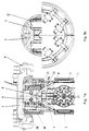
- Fig. 1a shows a vertical section through the apparatus.
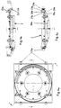
- Fig. 1b shows a horizontal section/outline of the apparatus.
- Fig. 2a and 2b show vertical sections through the honing tool.
- Fig. 3a-3c show a dismounting tool for the sealing rings of the sleeve.
- Fig. 4a-4c show a mounting tool for new sealing rings.
- Fig. 5-8 show different stages in the maintenance procedure.
- the intervention tool is shown in detail in figures 1-4 and comprises a bonnet 7 with external clamps 9.
- the bonnet is designed in order, by means of the clamps 9, to be secured to and to form a tight connection to a valve flange 53 (fig. 5) by means of sealing rings 28.
- the tool itself is secured to the under side of the bonnet 7 and comprises:
- FIG. 1a An embodiment of the rotating mechanism 8 is shown in fig. 1a and comprises a hydraulically operated rotating cylinder 8.
- the rotating cylinder 8 is connected to an axle 8a for rotation of the honing tool 1 with the pipe sleeves 52 as more closely described later.
- the honing tool 1 is mounted on a frame 4 which is directly connected to the shaft 8a of the rotating cylinder 8.
- the honing tool 1 is shown in an outline viewed from the one end of the tool, whilst in fig. 2a and 2b it is shown in a transversal section and in a larger scale.
- the honing tool 1 comprises two similarly shaped rotating grinding units at each end and where only one of them is shown in the figures 2a and 2b.
- Each grinding unit comprises a hydraulic drive motor 17 which by way of a gear rim and gear wheel 16 drives a rotating frame 15.
- the grinding unit comprises, further, a first grinding segment 10 for grinding a spherical sealing surface 56 in a valve housing and a second grinding segment 11 for grinding a conical seat comprising the valve sleeve's sealing surface.
- the grinding segments are mounted on ribs which open the conduit for through flow during honing.
- the honing of the spherical sealing surfaces takes place by the hydraulic cylinder 14 pressing the grinding segments 10 radially outwards while it rotates.
- the rotational movement is transferred from the hydraulic motor 17.
- Honing takes place until the frame of the grinding segments comes to rest against a prearranged abutment. The predetermined grinding measure is then removed.
- Honing of the valve sleeve's sealing surfaces is carried out by the hydraulic cylinder 12 forcing a sleeve-honing tool 11 axially forwards and into the seat.
- the seat and grinding elements are slightly conical, so that the radial progression is achieved automatically by the axial movement.
- the rotation of the honing tool is carried out by the hydraulic motor 17 and is transferred via the ribs 13.
- the honing of the conical sealing surfaces 51 is carried out until the honing tool reaches it's abutment and the predetermined grinding measure is removed. Centring during honing is taken care of, partly by the hub of the tool and partly by a cylindrical part in the tool in front of the grinding segments. This (cylindrical part) moves towards a corresponding cylindrical part inside the sleeve seat.
- the intervention tool also comprises a dismounting tool 3 for the dismounting of old metallic sealing rings 26a on the pipe sleeves and a mounting tool for the mounting of new sealing rings 26b adapted to the honed sealing surface.
- the dismounting tool is shown in detail in the figures 3a-3c and includes a main frame 18a, a gripping frame 19a, wedges 20a for expanding the locking ring 27a of the sleeve, springs 61a and guide pins 6a between the main frame 18a and the gripping frame 19a, a row of claw-shaped grippers 21a and a displaceable sleeve 22a which encloses the grippers 21a and facilitates radial movement of the grippers' 21a free end.
- each pipe sleeve 52 is moved out by means of its own cylinder.
- the wedges 20a are pushed by this movement in under the locking ring 27a and cause this to expand out of its groove on the pipe sleeve 52.
- the gripping frame 19a is pushed towards the main frame 18a and against the counter force from the springs 61a.
- fastly secured taps on the main frame 18a will press the moveable sleeve 22a up over the grippers 21a and push their free ends radially inwards so that the claw-formed end surface grips over the sealing ring 26a and secures it.
- the free end of the grippers is pushed radially inwards by the sleeve 22a and against the spring power of the springs arranged, for instance, underneath the grippers 21.
- the sealing ring 21a with the locking rings 27a will be secured by the apparatus.
- the left half of the figures show the apparatus prior to dismounting, whilst the right half shows the apparatus after dismounting has taken place and with the sealing rings 26a secured.
- the mounting tool has a design almost identical to that of the dismounting tool and comprises a main frame 18b, a gripping frame 19b, wedges 20b, a row of claw-formed grippers 21b which basically secures a new sealing ring 26b with a locking ring 27b and a moveable sleeve 22b which encloses the grippers 21b.
- the circle which is formed by the wedges 20b of the mounting tool, will have a somewhat lesser diameter than the internal diameter of the pipe sleeve 52. This causes the pipe sleeve 52d, when pushed forwards, to enter into the new locking ring 27b and to expand this. When the pipe sleeve 52 has reached the point where the locking ring 27b is level with the ring groove in the ring sleeve 52, the locking ring 27b will slip down into the ring groove and it will be axially fastened. As in the case of dismounting, the sleeve will push the gripping frame 19b during the movement, towards the main frame 18b against the action from the springs 61b.
- each locking ring 27b will come into position at the bottom of the ring groove of the pipe sleeve 52 and will lock the sealing ring 26b into place on the end of the sleeve.
- the new sealing rings are now mounted.
- the first part of the procedure will be that the bonnet of the valve and the upper part of the ball which is fastened to the bonnet are removed while the sleeves 52 of the valve are in an open position and allow normal through flow through the valve (see fig. 5).
- the hydraulic control system for the cylinder room 58 of the sleeves 52 is still in position underneath the sleeves 52.
- the next step in the procedure will be the mounting of the intervention tool, which is shown in fig. 1a, onto a valve flange 55.
- a dovetail guide (not shown) preferably arranged.
- Figure 6 shows the intervention tool mounted onto the valve where the bonnet 7 is secured to the valve flange 53 by means of the locking clamps 9 on the bonnet.
- the third step (fig. 7) in the procedure will be to retract the pipe sleeves 52. This is carried out by an annular space 57 being pressurized simultaneously with the annular space 58 being relieved. The pressure in the pipeline will thus spread to the entire inner valve housing.
- the fourth step in the procedure (fig. 8) can take place, which involves the honing tool 1 and the pipe sleeves 52 with associated parts being turned 90° by means of the rotating cylinder 8.
- the grinding tool will now have arrived in position and will be ready for the grinding of the valve seats and with the pipe sleeves 52 pointing towards guide rails 5, 32.
- the fifth step in the process will be grinding of the spherical surfaces and conical valve seats as described above.
- the surfaces on each side are honed simultaneously.
- the sixth step in the process will be dismounting of old sealing rings 26.
- the dismounting tool 3 is parked prior to use on the underside of the bonnet 7 in position A.
- the tool 3 is driven down into position B by means of a driving motor 6 and a chain transmission.
- the guide castors 25a of the dismounting tool 3 run along the more or less vertical guide rails 32. In the lower position the tool is fastened to the guide rails 32 by means of steering pins (not shown).
- the dismounting tool 3 is driven back to a parked position.
- the mounting tool 2 is driven down from the parked position C in fig. 1a to position D, since the guide castors 25b rest against the rails 5. Mounting of both sealing rings 26b takes place simultaneously and as described previously. When mounting is completed, the mounting tool 2 is driven back into parked position C.
- the intervention tool is now to be evacuated from the valve housing. Before this can take place, the following operations must be carried out:
- the pressure in the valve housing is bled out so that the pressure in the housing and the external pressure are equal.
- the intervention tool can now be released from the valve housing by the locking clamps 9 being withdrawn and the bonnet 7 with mounted tool being retracted out of the valve housing.
Landscapes
- General Engineering & Computer Science (AREA)
- Engineering & Computer Science (AREA)
- Mechanical Engineering (AREA)
- Check Valves (AREA)
- Grinding And Polishing Of Tertiary Curved Surfaces And Surfaces With Complex Shapes (AREA)
- Taps Or Cocks (AREA)
- Float Valves (AREA)
- Finish Polishing, Edge Sharpening, And Grinding By Specific Grinding Devices (AREA)
- Multiple-Way Valves (AREA)
- Pens And Brushes (AREA)
- Transition And Organic Metals Composition Catalysts For Addition Polymerization (AREA)
- Paper (AREA)
- Vehicle Body Suspensions (AREA)
- Gloves (AREA)
- Manipulator (AREA)
- Spinning Or Twisting Of Yarns (AREA)
Claims (10)
Priority Applications (1)
| Application Number | Priority Date | Filing Date | Title |
|---|---|---|---|
| AT88906866T ATE75016T1 (de) | 1987-08-17 | 1988-08-15 | Anordnung fuer die instandhaltung eines kugelventils. |
Applications Claiming Priority (2)
| Application Number | Priority Date | Filing Date | Title |
|---|---|---|---|
| NO873446A NO163505C (no) | 1987-08-17 | 1987-08-17 | Apparat for vedlikehold av kuleventil. |
| NO873446 | 1987-08-17 |
Publications (2)
| Publication Number | Publication Date |
|---|---|
| EP0338030A1 EP0338030A1 (de) | 1989-10-25 |
| EP0338030B1 true EP0338030B1 (de) | 1992-04-15 |
Family
ID=19890170
Family Applications (1)
| Application Number | Title | Priority Date | Filing Date |
|---|---|---|---|
| EP88906866A Expired - Lifetime EP0338030B1 (de) | 1987-08-17 | 1988-08-15 | Anordnung für die instandhaltung eines kugelventils |
Country Status (10)
| Country | Link |
|---|---|
| US (1) | US4901752A (de) |
| EP (1) | EP0338030B1 (de) |
| JP (1) | JP2650748B2 (de) |
| AT (1) | ATE75016T1 (de) |
| BR (1) | BR8807169A (de) |
| DE (1) | DE3870223D1 (de) |
| DK (1) | DK163737C (de) |
| FI (1) | FI89738C (de) |
| NO (1) | NO163505C (de) |
| WO (1) | WO1989001584A1 (de) |
Families Citing this family (8)
| Publication number | Priority date | Publication date | Assignee | Title |
|---|---|---|---|---|
| GB8817358D0 (en) * | 1988-07-21 | 1988-08-24 | Cooper Ind Inc | Clamp assemblies |
| US4931783A (en) * | 1988-07-26 | 1990-06-05 | Apple Computer, Inc. | Method and apparatus for removable menu window |
| NO166420C (no) * | 1988-10-14 | 1991-07-31 | Norske Stats Oljeselskap | Ventil. |
| NO166200C (no) * | 1989-02-10 | 1991-06-12 | Norske Stats Oljeselskap | Anordning ved dreieventil. |
| US8172198B2 (en) * | 2007-08-09 | 2012-05-08 | Goodrich Corporation | Valve assembly for aircraft water supply system |
| US9079281B2 (en) * | 2012-03-29 | 2015-07-14 | North American Fuel Systems Remanufacturing, LLC | Common rail valve seat refurbishing |
| CN108500775A (zh) * | 2018-05-29 | 2018-09-07 | 天津祥嘉流体控制系统有限公司 | 用于球阀球体研磨加工的研磨机 |
| CN111070027B (zh) * | 2019-12-18 | 2020-12-18 | 钢诺新材料股份有限公司 | 一种高效的耐磨球用打磨设备 |
Family Cites Families (8)
| Publication number | Priority date | Publication date | Assignee | Title |
|---|---|---|---|---|
| US1817917A (en) * | 1930-03-03 | 1931-08-11 | Carl W Carpenter | Valve |
| NO141832C (no) * | 1975-11-21 | 1980-05-21 | Per Jensen | Slipeapparat for sluseventiler. |
| US4114483A (en) * | 1977-04-08 | 1978-09-19 | Grimsley Ernest E | Portable boring tool for ball valves |
| US4346728A (en) * | 1980-07-28 | 1982-08-31 | Anchor/Darling Industries, Inc. | Automated dual mode valve actuator |
| US4468158A (en) * | 1982-11-29 | 1984-08-28 | The United States Of America As Represented By The Secretary Of The Navy | Inplace ball valve repair apparatus |
| US4610112A (en) * | 1984-09-17 | 1986-09-09 | John Kelsey | Apparatus for grinding and/or reconditioning plane, annular surfaces |
| US4654275A (en) * | 1985-11-27 | 1987-03-31 | Allied Corporation | Storage life of Pb-In-Ag solder foil by Sn addition |
| NO159553C (no) * | 1986-03-12 | 1989-01-11 | Norske Stats Oljeselskap | Kuleventil. |
-
1987
- 1987-08-17 NO NO873446A patent/NO163505C/no unknown
-
1988
- 1988-08-15 BR BR888807169A patent/BR8807169A/pt not_active IP Right Cessation
- 1988-08-15 EP EP88906866A patent/EP0338030B1/de not_active Expired - Lifetime
- 1988-08-15 US US07/346,023 patent/US4901752A/en not_active Expired - Lifetime
- 1988-08-15 JP JP63506793A patent/JP2650748B2/ja not_active Expired - Lifetime
- 1988-08-15 AT AT88906866T patent/ATE75016T1/de not_active IP Right Cessation
- 1988-08-15 DE DE8888906866T patent/DE3870223D1/de not_active Expired - Lifetime
- 1988-08-15 WO PCT/NO1988/000062 patent/WO1989001584A1/en not_active Ceased
-
1989
- 1989-04-14 DK DK180689A patent/DK163737C/da not_active IP Right Cessation
- 1989-04-14 FI FI891800A patent/FI89738C/fi not_active IP Right Cessation
Also Published As
| Publication number | Publication date |
|---|---|
| NO163505B (no) | 1990-02-26 |
| WO1989001584A1 (en) | 1989-02-23 |
| FI891800A0 (fi) | 1989-04-14 |
| DK163737C (da) | 1992-08-24 |
| EP0338030A1 (de) | 1989-10-25 |
| BR8807169A (pt) | 1989-10-17 |
| NO873446L (no) | 1989-02-20 |
| DK180689A (da) | 1989-04-14 |
| JP2650748B2 (ja) | 1997-09-03 |
| DK163737B (da) | 1992-03-30 |
| NO873446D0 (no) | 1987-08-17 |
| JPH02500579A (ja) | 1990-03-01 |
| FI891800L (fi) | 1989-04-14 |
| NO163505C (no) | 1990-06-06 |
| FI89738C (fi) | 1993-11-10 |
| DE3870223D1 (de) | 1992-05-21 |
| US4901752A (en) | 1990-02-20 |
| FI89738B (fi) | 1993-07-30 |
| ATE75016T1 (de) | 1992-05-15 |
| DK180689D0 (da) | 1989-04-14 |
Similar Documents
| Publication | Publication Date | Title |
|---|---|---|
| US4142739A (en) | Pipe connector apparatus having gripping and sealing means | |
| US4330143A (en) | Apparatus for connecting together flowline end portions | |
| US7789161B2 (en) | Apparatus for interconnecting and sealing between fixed and rotating conduits and methods of installing same | |
| EP0338030B1 (de) | Anordnung für die instandhaltung eines kugelventils | |
| US8308131B2 (en) | Ball valve stem retaining system | |
| GB1582392A (en) | Forging apparatus | |
| US3827448A (en) | Sub-sea pipeline tapping device | |
| US3717000A (en) | Jig for performing work in a weightless medium | |
| EP3516202B1 (de) | Injektorhülsenanordnung und verfahren zur reparatur vor ort | |
| EP3025062B1 (de) | Feste saugkammer mit hinter- und vorderdichtungsentfernung | |
| US4411456A (en) | Apparatus, methods, and joints for connecting tubular members | |
| US6260252B1 (en) | Method and apparatus for assembling or disassembling an installation present on a seabed | |
| CN108637867B (zh) | 一种水下管道打磨装置 | |
| EP4281699B1 (de) | Kombiniertes bohr- und stoppsystem | |
| US4485542A (en) | Seal placement and removal press for rotating machinery | |
| US20160069460A1 (en) | Ball valve stem retaining system | |
| CA1136835A (en) | Extractor tool | |
| US3656501A (en) | Valve-operator assembly with alignment and locking mechanism | |
| US4513542A (en) | Portable surfacing machine for boiler manhole | |
| CN1023949C (zh) | 滚动轴承尾轴尾管装置 | |
| JP2004535307A (ja) | ドリルステム用駆動装置 | |
| JPH0929520A (ja) | 管内加工装置 | |
| CN217177599U (zh) | 一种管道阀门控制装置 | |
| RU1790479C (ru) | Устройство дл обработки уплотнительных поверхностей клиновых задвижек | |
| JPH09155710A (ja) | 蒸気止め弁の摺合わせ装置 |
Legal Events
| Date | Code | Title | Description |
|---|---|---|---|
| PUAI | Public reference made under article 153(3) epc to a published international application that has entered the european phase |
Free format text: ORIGINAL CODE: 0009012 |
|
| 17P | Request for examination filed |
Effective date: 19890607 |
|
| AK | Designated contracting states |
Kind code of ref document: A1 Designated state(s): AT BE CH DE FR GB IT LI LU NL SE |
|
| 17Q | First examination report despatched |
Effective date: 19910610 |
|
| GRAA | (expected) grant |
Free format text: ORIGINAL CODE: 0009210 |
|
| ITF | It: translation for a ep patent filed | ||
| AK | Designated contracting states |
Kind code of ref document: B1 Designated state(s): AT BE CH DE FR GB IT LI LU NL SE |
|
| REF | Corresponds to: |
Ref document number: 75016 Country of ref document: AT Date of ref document: 19920515 Kind code of ref document: T |
|
| REF | Corresponds to: |
Ref document number: 3870223 Country of ref document: DE Date of ref document: 19920521 |
|
| ET | Fr: translation filed | ||
| PLBE | No opposition filed within time limit |
Free format text: ORIGINAL CODE: 0009261 |
|
| STAA | Information on the status of an ep patent application or granted ep patent |
Free format text: STATUS: NO OPPOSITION FILED WITHIN TIME LIMIT |
|
| 26N | No opposition filed | ||
| EPTA | Lu: last paid annual fee | ||
| EAL | Se: european patent in force in sweden |
Ref document number: 88906866.4 |
|
| REG | Reference to a national code |
Ref country code: GB Ref legal event code: IF02 |
|
| PGFP | Annual fee paid to national office [announced via postgrant information from national office to epo] |
Ref country code: SE Payment date: 20020806 Year of fee payment: 15 |
|
| PGFP | Annual fee paid to national office [announced via postgrant information from national office to epo] |
Ref country code: FR Payment date: 20020808 Year of fee payment: 15 |
|
| PGFP | Annual fee paid to national office [announced via postgrant information from national office to epo] |
Ref country code: AT Payment date: 20020813 Year of fee payment: 15 |
|
| PGFP | Annual fee paid to national office [announced via postgrant information from national office to epo] |
Ref country code: LU Payment date: 20020814 Year of fee payment: 15 Ref country code: GB Payment date: 20020814 Year of fee payment: 15 |
|
| PGFP | Annual fee paid to national office [announced via postgrant information from national office to epo] |
Ref country code: CH Payment date: 20020815 Year of fee payment: 15 |
|
| PGFP | Annual fee paid to national office [announced via postgrant information from national office to epo] |
Ref country code: DE Payment date: 20020821 Year of fee payment: 15 |
|
| PGFP | Annual fee paid to national office [announced via postgrant information from national office to epo] |
Ref country code: NL Payment date: 20020829 Year of fee payment: 15 |
|
| PGFP | Annual fee paid to national office [announced via postgrant information from national office to epo] |
Ref country code: BE Payment date: 20021017 Year of fee payment: 15 |
|
| PG25 | Lapsed in a contracting state [announced via postgrant information from national office to epo] |
Ref country code: LU Free format text: LAPSE BECAUSE OF NON-PAYMENT OF DUE FEES Effective date: 20030815 Ref country code: GB Free format text: LAPSE BECAUSE OF NON-PAYMENT OF DUE FEES Effective date: 20030815 Ref country code: AT Free format text: LAPSE BECAUSE OF NON-PAYMENT OF DUE FEES Effective date: 20030815 |
|
| PG25 | Lapsed in a contracting state [announced via postgrant information from national office to epo] |
Ref country code: SE Free format text: LAPSE BECAUSE OF NON-PAYMENT OF DUE FEES Effective date: 20030816 |
|
| PG25 | Lapsed in a contracting state [announced via postgrant information from national office to epo] |
Ref country code: LI Free format text: LAPSE BECAUSE OF NON-PAYMENT OF DUE FEES Effective date: 20030831 Ref country code: CH Free format text: LAPSE BECAUSE OF NON-PAYMENT OF DUE FEES Effective date: 20030831 Ref country code: BE Free format text: LAPSE BECAUSE OF NON-PAYMENT OF DUE FEES Effective date: 20030831 |
|
| BERE | Be: lapsed |
Owner name: *DEN NORSKE STATS OLJESELSKAP A.S. Effective date: 20030831 |
|
| PG25 | Lapsed in a contracting state [announced via postgrant information from national office to epo] |
Ref country code: NL Free format text: LAPSE BECAUSE OF NON-PAYMENT OF DUE FEES Effective date: 20040301 |
|
| PG25 | Lapsed in a contracting state [announced via postgrant information from national office to epo] |
Ref country code: DE Free format text: LAPSE BECAUSE OF NON-PAYMENT OF DUE FEES Effective date: 20040302 |
|
| EUG | Se: european patent has lapsed | ||
| GBPC | Gb: european patent ceased through non-payment of renewal fee |
Effective date: 20030815 |
|
| REG | Reference to a national code |
Ref country code: CH Ref legal event code: PL |
|
| PG25 | Lapsed in a contracting state [announced via postgrant information from national office to epo] |
Ref country code: FR Free format text: LAPSE BECAUSE OF NON-PAYMENT OF DUE FEES Effective date: 20040430 |
|
| NLV4 | Nl: lapsed or anulled due to non-payment of the annual fee |
Effective date: 20040301 |
|
| REG | Reference to a national code |
Ref country code: FR Ref legal event code: ST |
|
| PG25 | Lapsed in a contracting state [announced via postgrant information from national office to epo] |
Ref country code: IT Free format text: LAPSE BECAUSE OF NON-PAYMENT OF DUE FEES;WARNING: LAPSES OF ITALIAN PATENTS WITH EFFECTIVE DATE BEFORE 2007 MAY HAVE OCCURRED AT ANY TIME BEFORE 2007. THE CORRECT EFFECTIVE DATE MAY BE DIFFERENT FROM THE ONE RECORDED. Effective date: 20050815 |