EP0337939B1 - Inductive sensor arrangement and measuring arrangement determining the relative position of a sensor arrangement - Google Patents
Inductive sensor arrangement and measuring arrangement determining the relative position of a sensor arrangement Download PDFInfo
- Publication number
- EP0337939B1 EP0337939B1 EP19890810201 EP89810201A EP0337939B1 EP 0337939 B1 EP0337939 B1 EP 0337939B1 EP 19890810201 EP19890810201 EP 19890810201 EP 89810201 A EP89810201 A EP 89810201A EP 0337939 B1 EP0337939 B1 EP 0337939B1
- Authority
- EP
- European Patent Office
- Prior art keywords
- arrangement
- receiver
- coil
- winding portions
- detection region
- Prior art date
- Legal status (The legal status is an assumption and is not a legal conclusion. Google has not performed a legal analysis and makes no representation as to the accuracy of the status listed.)
- Expired - Lifetime
Links
Images
Classifications
-
- G—PHYSICS
- G01—MEASURING; TESTING
- G01B—MEASURING LENGTH, THICKNESS OR SIMILAR LINEAR DIMENSIONS; MEASURING ANGLES; MEASURING AREAS; MEASURING IRREGULARITIES OF SURFACES OR CONTOURS
- G01B7/00—Measuring arrangements characterised by the use of electric or magnetic techniques
- G01B7/02—Measuring arrangements characterised by the use of electric or magnetic techniques for measuring length, width or thickness
- G01B7/023—Measuring arrangements characterised by the use of electric or magnetic techniques for measuring length, width or thickness for measuring distance between sensor and object
-
- G—PHYSICS
- G01—MEASURING; TESTING
- G01D—MEASURING NOT SPECIALLY ADAPTED FOR A SPECIFIC VARIABLE; ARRANGEMENTS FOR MEASURING TWO OR MORE VARIABLES NOT COVERED IN A SINGLE OTHER SUBCLASS; TARIFF METERING APPARATUS; MEASURING OR TESTING NOT OTHERWISE PROVIDED FOR
- G01D5/00—Mechanical means for transferring the output of a sensing member; Means for converting the output of a sensing member to another variable where the form or nature of the sensing member does not constrain the means for converting; Transducers not specially adapted for a specific variable
- G01D5/12—Mechanical means for transferring the output of a sensing member; Means for converting the output of a sensing member to another variable where the form or nature of the sensing member does not constrain the means for converting; Transducers not specially adapted for a specific variable using electric or magnetic means
- G01D5/14—Mechanical means for transferring the output of a sensing member; Means for converting the output of a sensing member to another variable where the form or nature of the sensing member does not constrain the means for converting; Transducers not specially adapted for a specific variable using electric or magnetic means influencing the magnitude of a current or voltage
- G01D5/20—Mechanical means for transferring the output of a sensing member; Means for converting the output of a sensing member to another variable where the form or nature of the sensing member does not constrain the means for converting; Transducers not specially adapted for a specific variable using electric or magnetic means influencing the magnitude of a current or voltage by varying inductance, e.g. by a movable armature
- G01D5/22—Mechanical means for transferring the output of a sensing member; Means for converting the output of a sensing member to another variable where the form or nature of the sensing member does not constrain the means for converting; Transducers not specially adapted for a specific variable using electric or magnetic means influencing the magnitude of a current or voltage by varying inductance, e.g. by a movable armature differentially influencing two coils
- G01D5/2208—Mechanical means for transferring the output of a sensing member; Means for converting the output of a sensing member to another variable where the form or nature of the sensing member does not constrain the means for converting; Transducers not specially adapted for a specific variable using electric or magnetic means influencing the magnitude of a current or voltage by varying inductance, e.g. by a movable armature differentially influencing two coils by influencing the self-induction of the coils
-
- G—PHYSICS
- G01—MEASURING; TESTING
- G01D—MEASURING NOT SPECIALLY ADAPTED FOR A SPECIFIC VARIABLE; ARRANGEMENTS FOR MEASURING TWO OR MORE VARIABLES NOT COVERED IN A SINGLE OTHER SUBCLASS; TARIFF METERING APPARATUS; MEASURING OR TESTING NOT OTHERWISE PROVIDED FOR
- G01D5/00—Mechanical means for transferring the output of a sensing member; Means for converting the output of a sensing member to another variable where the form or nature of the sensing member does not constrain the means for converting; Transducers not specially adapted for a specific variable
- G01D5/12—Mechanical means for transferring the output of a sensing member; Means for converting the output of a sensing member to another variable where the form or nature of the sensing member does not constrain the means for converting; Transducers not specially adapted for a specific variable using electric or magnetic means
- G01D5/14—Mechanical means for transferring the output of a sensing member; Means for converting the output of a sensing member to another variable where the form or nature of the sensing member does not constrain the means for converting; Transducers not specially adapted for a specific variable using electric or magnetic means influencing the magnitude of a current or voltage
- G01D5/20—Mechanical means for transferring the output of a sensing member; Means for converting the output of a sensing member to another variable where the form or nature of the sensing member does not constrain the means for converting; Transducers not specially adapted for a specific variable using electric or magnetic means influencing the magnitude of a current or voltage by varying inductance, e.g. by a movable armature
- G01D5/22—Mechanical means for transferring the output of a sensing member; Means for converting the output of a sensing member to another variable where the form or nature of the sensing member does not constrain the means for converting; Transducers not specially adapted for a specific variable using electric or magnetic means influencing the magnitude of a current or voltage by varying inductance, e.g. by a movable armature differentially influencing two coils
- G01D5/225—Mechanical means for transferring the output of a sensing member; Means for converting the output of a sensing member to another variable where the form or nature of the sensing member does not constrain the means for converting; Transducers not specially adapted for a specific variable using electric or magnetic means influencing the magnitude of a current or voltage by varying inductance, e.g. by a movable armature differentially influencing two coils by influencing the mutual induction between the two coils
Definitions
- the invention relates to an inductive sensor arrangement according to the preamble of claim 1 and its use in a measuring arrangement according to the preamble of claim 7 or 8.
- a sensor arrangement is e.g. known from the applicant's EP-A-98 238.
- an alternating field is induced in a plurality of receiver coils by at least one transmitter coil fed by an RF oscillator.
- This is influenced by the approach of a metallic object into an object detection area, ie into the electromagnetic field.
- This also influences the induced voltage in the receiver partial windings, whereby both phase shifts in the individual partial windings and amplitude fluctuations can occur.
- This alternating field generated by the transmitter coil thus induces an alternating voltage which is dependent on the position of the object in the object detection area in the partial windings of the receiver coil arrangement.
- the receiver coil is subdivided into two or more partial windings which, when the object changes position, move away from or approach the object differently. This results in a different field distribution of the RF fields and a phase shift in the two partial windings.
- the change in position of the object can be determined in the simplest way. The easiest way to do this is to connect the partial windings directly ("directly") with the opposite winding sense, so that remove the partial voltages of the partial windings, provided that they are influenced in the same way by the object.
- the two partial windings are influenced differently and the partial voltages are only partially compensated for, so that the receiver coil emits a usable output signal. Since the position of the object also changes the inductance of the partial windings of the receiver coil, the change in position also results in a different inductance change of the two partial windings, so that a phase change in the AC voltage at the output of the receiver coil can be determined compared to the signal of the transmitter coil.
- the known sensor arrangement is suitable for scanning object irregularities, such as gaps in metal plates or weld seams and the like. It has proven useful that the partial windings are arranged perpendicular to the object on both sides of the object irregularity.
- the gap lies exactly in the middle between the two receiver partial windings, the same voltages and currents are induced, so that the system is in equilibrium and can be used, for example, in a control loop to track a seam or to find a hole.
- Difficulties can arise if, for example, when tracking a gap, the object on one side of the gap is closer to the receiver partial winding above it than the object on the other side of the gap in relation to the assigned partial winding.
- the electromagnetic field is not only influenced by the irregularity of the object, ie the gap, but is also asymmetrically damped by the different object spacing of the two partial windings.
- the object of the invention is therefore to create an inductive sensor arrangement or a measuring arrangement for determining the relative position of such a sensor arrangement to an object, in which distance errors e.g. are easier to compensate for when tracking seams or other object irregularities, so that the sensor arrangement can more accurately follow the actual course of the seam or the object irregularity.
- each of the two coil arrangements has only two receiver sub-coils - a typical arrangement for tracking gaps or weld seams.
- the arrangement is also identical to three, four or more Realize partial receiver windings per coil arrangement. Such arrangements are then typically used to find holes or other circular or point-shaped object irregularities.
- the invention therefore initially assumes that the partial windings of the first winding arrangements are directly or indirectly coupled in a known manner, so that the difference signal derived from the two partial windings corresponds to the lateral offset of the object irregularity.
- each of the partial windings of the first coil arrangement is assigned a partial winding of the second coil arrangement.
- the two partial windings are approximately aligned. Due to the different distance to the object, each change in distance of the object under the two aligned partial windings leads to a different change in the induction in the two partial windings.
- the comparison of these different changes in induction in the two partial windings lying one above the other can be used to obtain a signal corresponding to the distance of the object between the partial windings.
- This signal corresponds particularly precisely to the effective distance of the object to the partial winding of the first coil arrangement for measuring the lateral offset, because this partial winding is used both for the generation of lateral offset signals and - in connection with the partial winding of the second coil arrangement above it - for the acquisition of distance signals.
- the sensor arrangement can be implemented particularly easily if the partial windings of the first coil arrangement are directly connected to one another and at the same time are connected directly to the partial windings of the second coil arrangement in order to obtain the signals proportional to the distance.
- the invention can also be implemented if each of the individual Coils are derived and determined, for example, via an amplifier and / or rectifier, and then these signals are indirectly compared with one another or switched against one another.
- good sensitivity of the sensor arrangement can be achieved if the winding axes of the transmitter coil and the winding axes of the receiver coils are directed towards the object detection area or towards the object.
- a symmetrical, namely point-symmetrical or axially symmetrical arrangement of the partial windings is advantageously suitable for locating or tracking linear or point-shaped object irregularities.
- the partial windings of each coil arrangement should be arranged in one plane in relation to the object detection area. If the object has a different shape, and e.g. requires a cylindrical or angular object detection area (e.g. pipe seam tracking), the partial windings of the coil arrangements can also be arranged at any angle or curved, as is e.g. in EP-A-130 940 of the applicant.
- the partial windings can be designed with or without a core.
- What is essential here is the direct inductive coupling of the transmitter coil or transmitter coils and the entirety of the partial windings of the receiver coil arrangements in order to obtain precise signals corresponding to the lateral offset and the distance of the partial windings from the object.
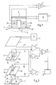
- FIG. 1 shows a known arrangement in which a transmitter coil 1 is arranged on a core 2.
- the transmitter coil 1 is fed by an HF oscillator 3 and generates an electromagnetic field which detects the core 2 and a metallic object 4a, 4b which lies in the area of influence of the electromagnetic field or the object detection area 5 of the transmitter coil 1.
- the side 4a of the object 4 lies closer to the core 2 than the side 4b of the object 4.
- the sides 4a, 4b of the object 4 are separated from one another by a slot 4c.
- Two receiver partial windings 6a, 6b are located in the electromagnetic field of the transmitter coil 1.
- the electromagnetic field of the transmitter coil would be absolutely uniform and would accordingly produce the same induction in terms of magnitude and voltage in the identically constructed and symmetrically arranged but sub-receiver partial windings 6a, 6b. In such a case, no signal was present at the input of an amplifier 7. However, the field of the transmitter coil 1 and also the subfields in the receiver partial windings 6a, 6b are changed by the object 4 and the eddy currents induced in the object. For example, an approximation of the slot 4c to one of the partial windings has the effect that it is damped less than the other partial winding.
- the signal of the less damped partial winding predominates and there is a distinguishable signal at the input of the amplifier 7.
- This signal can be used in a known manner, for example to control a readjustment device which, by means of evaluation and drive devices (not shown), moves the core 2 and / or the object 4 until no more signal is emitted by the amplifier 7 - which results in symmetrical conditions in the partial windings 6a, 6b and thus corresponds to a central alignment of the core 2 over the slot 4c.
- the receiver partial winding 6a is influenced to a greater extent, which is superimposed on the signal which is obtained from a center offset of the slot 4c relative to the core 2.
- Different distances a and b accordingly lead to a measurement error, which leads to misalignment of the core 2 relative to the slot 4c.
- FIG. 2 shows a schematic arrangement in which, for the sake of clarity, coils are only indicated with a single winding.
- a transmitter coil 1 is again provided, which is connected to an RF oscillator 3.
- a first coil arrangement 6 consists of two identical, but oppositely wound receiver partial windings 6a, 6b.
- the partial windings 6a, 6b are connected via lines 8a, 8b to an evaluation circuit indicated as an amplifier 7.
- a second coil arrangement 9 which likewise has two receiver partial windings 9a, 9b.
- the center tap 6c or 9c of the first coil arrangement 6 and the second coil arrangement 9 are connected to one another via a line 10. This causes the partial winding 6a and the partial winding 9a to be connected to one another.
- a signal can thus be tapped from line 8a and line 11, which corresponds to the difference between the signals induced by transmitter coil 1 in partial winding 9a and partial winding 6a. This difference signal is applied via line 8a and line 11 to the input of an amplifier 12.
- the windings 6b and 9b of the first coil arrangement 6 and the second coil arrangement 9 are connected to one another, so that a signal is present on lines 8b and 13 which results from the difference between the induction by the transmitter coil 1 and the partial winding 6b and 9b results.
- This signal is applied to the input of an amplifier 14. Since the object 4 is further away from the second coil arrangement 9 than from the first coil arrangement 6, a change in the distance of the object 4 leads to a weaker one Influencing the partial windings 9a, 9b as the partial windings 6a, 6b.
- the input signals at the amplifiers 12 and 14 thus correspond to the distance of the object 4 from the first coil arrangement 6a.
- the output signal of the amplifier 7, which should correspond to the lateral offset of the two partial windings 6a, 6b to the slot 4c, is compensated in such a way that differences in the distances a, b do not falsify the lateral offset measured value.
- correction signals can be derived in an optimally simple manner, which lead to an increase in the accuracy of the lateral offset signals. Since the partial windings 6a, 6b of the first coil arrangement both for obtaining the lateral offset signal by means of amplifier 7 and for obtaining the relative distance signals by means of amplifier 12, 14 and Ver 15 are used, it is ensured that the distance signals obtained actually correspond to the respective object distance of the partial windings 6a, 6b.
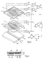
- FIG. 3 shows an embodiment in which the same components are provided with the same reference numerals.
- the partial windings 6a, 6b and 9a, 9b and the transmitter coil 1 are arranged as flat layers on insulating carrier disks 18, 19.
- the partial windings 6a, 6b, 9a, 9b are each formed axially symmetrically with respect to an axis of symmetry X.
- the mode of operation of the arrangement is analogous to the circuit arrangement according to FIG. 2. The only difference is that the partial windings 6a, 6b and 9a, 9b are not connected directly to one another but are each connected individually to signal amplifiers 20, 21, 22 and 23.
- a shift of the slot 4c from the region of the axis of symmetry X leads to the partial windings 6a and 6b delivering a different output signal to the amplifiers 20, 21.
- the lateral offset signal obtained in this way is determined in the comparison arrangement 24 and, via the compensation circuit 16, is applied to a schematically represented controller 25, which controls a tracking motor until the object 4 is again exactly below the axis of symmetry with the slot 4c by means of a mechanical tracking device, not shown X lies.
- the evaluation circuit is the receiver part Winding 6a connected to the partial winding 9a of the second coil arrangement in the following way:
- the partial winding 9a is connected on the output side to the signal amplifier 23, which in turn is connected to one input of a comparator 27.
- the signal amplifier 20 connected to the partial winding 6a is connected on the output side to the second input of the comparator 27.
- At the output of the comparator 27 there is accordingly a signal which corresponds to the difference between the voltages induced in the partial windings 6a and 9a.
- a comparator 28 As long as the distance between the side 4a and the partial winding 6a or the distance between the side 4b and the partial winding 6b is identical during operation, there is therefore an identical signal at the outputs of the comparators 27, 28.
- These two signals are each applied to the plus or minus input of a compensation comparator 29, which does not output an output signal when the signal inputs are identical.
- the compensation comparator 29 if the distance between one of the partial windings 6a or 6b and object 4 changes, then there are different signals at the input of the compensation comparator 29, so that the latter outputs a compensation signal to a compensation circuit 16 via line 30.
- the lateral offset signal emitted by the comparison arrangement 24 is then corresponding corrects the determined height offset and sends the signal corrected in this way to the controller 25.
- the double function of the partial windings 6a and 6b on the one hand to determine the lateral offset and on the other hand to determine the vertical offset in conjunction with the partial windings 9a and 9b guarantees an accurate correction of the lateral offset signals in an optimally simple manner.
- the carriers 18 and 19 are drawn at a distance from one another in FIG. Figure 4 shows how the arrangement can be designed in practice. The two carriers 18 and 19 are then connected to one another, with the receiver partial windings 6a and 6b being received between them.
- the partial windings can e.g. be applied in the technology known for printed circuits or also in thick film technology.
Description
Die Erfindung betrifft eine induktive Sensoranordnung gemäss Oberbegriff von Patentanspruch 1 und deren Verwendung in einer Messanordnung gemäss Oberbegriff von Patentanspruch 7 oder 8. Eine derartige Sensoranordnung ist z.B. aus der EP-A-98 238 der Anmelderin bekannt.The invention relates to an inductive sensor arrangement according to the preamble of claim 1 and its use in a measuring arrangement according to the preamble of claim 7 or 8. Such a sensor arrangement is e.g. known from the applicant's EP-A-98 238.
Bei solchen induktiven Sensoranordnungen wird durch wenigstens eine von einem HF-Oszillator gespeiste Senderspule ein Wechselfeld in eine Mehrzahl von Empfängerspulen induziert. Durch Annäherung eines metallischen Objekts in einen Objekt-Erfassungsbereich, d.h. in das elektromagnetische Feld, wird dieses beeinflusst. Dadurch wird die induzierte Spannung in die Empfänger-Teilwicklungen ebenfalls beeinflusst, wobei sowohl Phasenverschiebungen in den einzelnen Teilwicklungen als auch Amplitudenschwankungen auftreten können. Dies resultiert in erster Linie daraus, dass durch das elektromagnetische Feld der Senderspule im metallischen Objekt Wirbelströme erzeugt werden, die auf das elektromagnetische Feld zurückwirken. Dieses durch die Senderspule erzeugte Wechselfeld induziert in den Teilwicklungen der Empfängerspulen-Anordnung also eine von der Lage des Objekts im Objekterfassungsbereich abhängige Wechselspannung. Bei der bekannten Anordnung ist die Empfängerspule in zwei oder mehr Teilwicklungen unterteilt, die sich bei einer Lageveränderung des Objekts unterschiedlich vom Objekt entfernen bzw. diesem nähern. Dadurch ergibt sich eine unterschiedliche Feldverteilung der HF-Felder und eine Phasenverschiebung in den beiden Teilwicklungen. Durch Vergleich der Teilspannungen der beiden Teilwicklungen lässt sich dabei auf einfachste Weise die Lageveränderung des Objekts ermitteln. Am einfachsten kann dies dadurch erfolgen, dass die Teilwicklungen unmittelbar ("direkt") mit entgegengesetztem Wicklungssinn zusammengeschaltet sind, so dass sich die Teilspannungen der Teilwicklungen aufheben, sofern sie in gleicher Weise durch das Objekt beeinflusst werden. Aendert sich dagegen die Relativlage des Objekts, dann tritt eine unterschiedliche Beeinflussung der beiden Teilwicklungen auf und die Teilspannungen kompensieren sich nur mehr teilweise, so dass die Empfängerspule ein verwertbares Ausgangssignal abgibt. Da durch Lageveränderung des Objekts auch eine Induktivitätsänderung der Teilwicklungen der Empfängerspule bewirkt wird, resultiert aus der Lageveränderung auch eine unterschiedliche Induktivitätsänderung der beiden Teilwicklungen, so dass eine Phasenänderung der Wechselspannung am Ausgang der Empfängerspule verglichen mit dem Signal der Senderspule ermittelt werden kann. Die bekannte Sensoranordnung eignet sich zum Abtasten von Objektunregelmässigkeiten, wie z.B. Spalten in Metallplatten oder Schweissnähte und dergleichen. Dabei hat es sich bewährt, dass die Teilwicklungen senkrecht zum Objekt zu beiden Seiten der Objektunregelmässigkeit angeordnet sind. Sobald eine der Empfänger-Teilwicklungen näher an der Objektunregelmässigkeit z.B. dem Spalt liegt, tritt eine unterschiedliche Beeinflussung in den beiden Empfänger-Teilwicklungen auf, was zu einem verwertbaren Ausgangssignal führt. Liegt der Spalt genau mittig zwischen den beiden Empfänger-Teilwicklungen werden gleiche Spannungen und Ströme induziert, so dass das System im Gleichgewicht ist und z.B. in einem Regelkreis zur Verfolgung einer Naht oder zum Auffinden eines Loches eingesetzt werden kann.In such inductive sensor arrangements, an alternating field is induced in a plurality of receiver coils by at least one transmitter coil fed by an RF oscillator. This is influenced by the approach of a metallic object into an object detection area, ie into the electromagnetic field. This also influences the induced voltage in the receiver partial windings, whereby both phase shifts in the individual partial windings and amplitude fluctuations can occur. This results primarily from the fact that the electromagnetic field of the transmitter coil generates eddy currents in the metallic object, which have an effect on the electromagnetic field. This alternating field generated by the transmitter coil thus induces an alternating voltage which is dependent on the position of the object in the object detection area in the partial windings of the receiver coil arrangement. In the known arrangement, the receiver coil is subdivided into two or more partial windings which, when the object changes position, move away from or approach the object differently. This results in a different field distribution of the RF fields and a phase shift in the two partial windings. By comparing the partial voltages of the two partial windings, the change in position of the object can be determined in the simplest way. The easiest way to do this is to connect the partial windings directly ("directly") with the opposite winding sense, so that remove the partial voltages of the partial windings, provided that they are influenced in the same way by the object. However, if the relative position of the object changes, the two partial windings are influenced differently and the partial voltages are only partially compensated for, so that the receiver coil emits a usable output signal. Since the position of the object also changes the inductance of the partial windings of the receiver coil, the change in position also results in a different inductance change of the two partial windings, so that a phase change in the AC voltage at the output of the receiver coil can be determined compared to the signal of the transmitter coil. The known sensor arrangement is suitable for scanning object irregularities, such as gaps in metal plates or weld seams and the like. It has proven useful that the partial windings are arranged perpendicular to the object on both sides of the object irregularity. As soon as one of the receiver sub-windings is closer to the object irregularity, for example the gap, a different influence occurs in the two receiver sub-windings, which leads to a usable output signal. If the gap lies exactly in the middle between the two receiver partial windings, the same voltages and currents are induced, so that the system is in equilibrium and can be used, for example, in a control loop to track a seam or to find a hole.
Schwierigkeiten können sich dabei dann ergeben, wenn z.B. bei Verfolgung eines Spalts, das Objekt auf einer Seite des Spalts näher an der darüberliegenden Empfänger-Teilwicklung liegt, als das Objekt auf der anderen Seite des Spalts bezogen auf die zugeordnete Teilwicklung liegt. Ersichtlicherweise wird nämlich dabei das elektromagnetische Feld nicht nur durch die Objektunregelmässigkeit, d.h. den Spalt beeinflusst, sondern auch assymmetrisch gedämpft durch unterschiedlichen Objekt-Abstand der beiden Teilwicklungen.Difficulties can arise if, for example, when tracking a gap, the object on one side of the gap is closer to the receiver partial winding above it than the object on the other side of the gap in relation to the assigned partial winding. Obviously, the electromagnetic field is not only influenced by the irregularity of the object, ie the gap, but is also asymmetrically damped by the different object spacing of the two partial windings.
Um dies zu kompensieren, wurde bereits vorgeschlagen, zwei separate Abstandssensoren vorzusehen, mit welchen lediglich der Objektabstand gemessen wird. Aus unterschiedlichen Abstandsmesswerten lässt sich dann ein Kompensationssignal gewinnen, welches zur Korrektur des Seitenversatzsignals der beiden Empfänger-Teilwicklungen verwendet werden kann. Dabei hat es sich gezeigt, dass die von den Abstands-Sensoren gewonnenen Signale schon deshalb nicht exakt den Abstandsänderungen der Empfänger-Teilwicklungen entsprechen können, weil es sich dabei um separate Sensoren handelt, deren Lage und Beeinflussung durch das Objekt nicht genau identisch mit der Lage und der Beeinflussung in den beiden Empfänger-Teilwicklungen ist, von welchen die Seitenversatzsignale abgeleitet werden sollen. In bestimmten Anwendungsfällen verbleibt deshalb ein nicht kompensierbarer Restfehler.To compensate for this, it has already been proposed to provide two separate distance sensors with which only the object distance is measured. A compensation signal can then be obtained from different measured distance values, which can be used to correct the lateral offset signal of the two receiver partial windings. It has been shown that the signals obtained from the distance sensors cannot correspond exactly to the changes in the distance of the partial receiver windings, because they are separate sensors whose position and influence by the object are not exactly identical to the position and the influence in the two receiver sub-windings from which the lateral offset signals are to be derived. In certain applications, a residual error that cannot be compensated therefore remains.
Aufgabe der Erfindung ist es also, eine induktive Sensoranordnung bzw. eine Messanordnung zum Ermitteln der Relativlage einer solchen Sensoranordnung zu einem Objekt zu schaffen, bei welchem Abstandsfehler z.B. bei der Verfolgung von Nähten oder anderen Objektunregelmässigkeiten besser kompensierbar sind, so dass die Sensoranordnung exakter dem wirklichen Verlauf der Naht bzw. der Objektunregelmässigkeit folgen kann.The object of the invention is therefore to create an inductive sensor arrangement or a measuring arrangement for determining the relative position of such a sensor arrangement to an object, in which distance errors e.g. are easier to compensate for when tracking seams or other object irregularities, so that the sensor arrangement can more accurately follow the actual course of the seam or the object irregularity.
Eine solche Anordnung soll dabei mit einem Minimum an schaltungstechnischem Aufwand und in kompakter Sensor-Bauweise realisierbar sein. Erfindungsgemäss wird diese Aufgabe in erster Linie durch eine Anordnung gemäss Kennzeichen von Anspruch 1 gelöst. Der Einfachheit halber wird bei der nachfolgenden Schilderung davon ausgegangen, dass jede der beiden Spulenanordnungen lediglich zwei Empfänger-Teilspulen aufweist - eine typische Anordnung zur Verfolgung von Spalten oder Schweissnähten. Selbstverständlich ist die Anordnung je nach Anwendungsgebiet auch identisch mit drei, vier oder mehr Empfänger-Teilwicklungen je Spulenanordnung zu realisieren. Solche Anordnungen dienen dann typischerweise der Auffindung von Löchern oder anderen kreis- oder punktförmigen Objektunregelmässigkeiten.Such an arrangement should be able to be implemented with a minimum of circuitry outlay and in a compact sensor design. According to the invention, this object is achieved primarily by an arrangement according to the characterizing part of claim 1. For the sake of simplicity, the following description assumes that each of the two coil arrangements has only two receiver sub-coils - a typical arrangement for tracking gaps or weld seams. Of course, depending on the area of application, the arrangement is also identical to three, four or more Realize partial receiver windings per coil arrangement. Such arrangements are then typically used to find holes or other circular or point-shaped object irregularities.
Die Erfindung geht also zunächst davon aus, dass die Teilwicklungen der ersten Spulanordnungen in bekannter Weise direkt oder indirekt gegengekoppelt sind, so dass das von den beiden Teilwicklungen abgeleitete Differenzsignal dem Seitenversatz der Objektunregelmässigkeit entspricht. Ausserdem ist jeder der Teilwicklungen der ersten Spulenanordnung eine Teilwicklung der zweiten Spulenanordnung zugeordnet. Bezogen auf den Objekterfassungsbereich bzw. das Objekt fluchten die beiden Teilwicklungen etwa. Aufgrund des unterschiedlichen Abstands zum Objekt führt jede Abstandsänderung des Objekts unter den beiden fluchtenden Teilwicklungen dazu, dass eine unterschiedliche Veränderung der Induktion in die beiden Teilwicklungen auftritt. Der Vergleich dieser unterschiedlichen Induktionsänderungen in den beiden übereinanderliegenden Teilwicklungen lässt sich dazu nutzen, ein dem Abstand des Objekts unter den Teilwicklungen entsprechendes Signal zu gewinnen. Dieses Signal entspricht besonders exakt dem effektiven Abstand des Objekts zur Teilwicklung der ersten Spulenanordnung zur Messung des Seitenversatzes, weil diese Teilwicklung sowohl zur Gewinnung von Seitenversatzsignalen als auch - in Zusammenschaltung mit der darüberliegenden Teilwicklung der zweiten Spulenanordnung - zur Gewinnung von Abstandssignalen verwendet wird.The invention therefore initially assumes that the partial windings of the first winding arrangements are directly or indirectly coupled in a known manner, so that the difference signal derived from the two partial windings corresponds to the lateral offset of the object irregularity. In addition, each of the partial windings of the first coil arrangement is assigned a partial winding of the second coil arrangement. In relation to the object detection area or the object, the two partial windings are approximately aligned. Due to the different distance to the object, each change in distance of the object under the two aligned partial windings leads to a different change in the induction in the two partial windings. The comparison of these different changes in induction in the two partial windings lying one above the other can be used to obtain a signal corresponding to the distance of the object between the partial windings. This signal corresponds particularly precisely to the effective distance of the object to the partial winding of the first coil arrangement for measuring the lateral offset, because this partial winding is used both for the generation of lateral offset signals and - in connection with the partial winding of the second coil arrangement above it - for the acquisition of distance signals.
Besonders einfach lässt sich dabei die Sensoranordnung realisieren, wenn die Teilwicklungen der ersten Spulenanordnung untereinander direkt gegengeschaltet sind und gleichzeitig unmittelbar gegen die Teilwicklungen der zweiten Spulenanordnung geschaltet sind, um die abstandsproportionalen Signale zu gewinnen. Selbstverständlich lässt sich aber auch die Erfindung realisieren wenn zunächst von jeder der Einzel- Spulen z.B. über einen Verstärker und/oder Gleichrichter Signale abgeleitet und ermittelt werden, und sodann diese Signale indirekt miteinander verglichen bzw. gegeneinander geschaltet werden.The sensor arrangement can be implemented particularly easily if the partial windings of the first coil arrangement are directly connected to one another and at the same time are connected directly to the partial windings of the second coil arrangement in order to obtain the signals proportional to the distance. Of course, however, the invention can also be implemented if each of the individual Coils are derived and determined, for example, via an amplifier and / or rectifier, and then these signals are indirectly compared with one another or switched against one another.
Insbesondere zur Verfolgung von Nähten oder Spalten in metallischen Objekten lässt sich gute Empfindlichkeit der Sensoranordnung erreichen, wenn die Wicklungsachsen der Senderspule und die Wicklungsachsen der Empfängerspulen zum Objekt-Erfassungsbereich bzw. zum Objekt hin gerichtet sind.In particular for tracking seams or gaps in metallic objects, good sensitivity of the sensor arrangement can be achieved if the winding axes of the transmitter coil and the winding axes of the receiver coils are directed towards the object detection area or towards the object.
Besonders gute Differenzierung der Abstandssignale, die von den, bezogen auf den Objekterfassungsbereich, übereinanderliegenden Teilwicklungen gewonnen werden, lässt sich erreichen, wenn beide Empfänger-Spulenanordnungen bezogen auf den Objekterfassungsbereich, auf der gleichen Seite der Sender-Spule angeordnet sind.Particularly good differentiation of the distance signals, which are obtained from the partial windings lying one above the other in relation to the object detection area, can be achieved if both receiver coil arrangements are arranged on the same side of the transmitter coil in relation to the object detection area.
Symmetrische, und zwar punktsymmetrische oder axialsymmetrische Anordnung der Teilwicklungen eignet sich vorteilhaft zur Auffindung oder Verfolgung linienförmiger oder punktförmiger Objektunregelmässigkeiten.A symmetrical, namely point-symmetrical or axially symmetrical arrangement of the partial windings is advantageously suitable for locating or tracking linear or point-shaped object irregularities.
Bei flächigen Objekten sollen die Teilwicklungen jeder Spulenanordnung in einer Ebene, bezogen auf den Objekt-Erfassungsbereich angeordnet sein. Sofern das Objekt eine andere Form aufweist, und z.B. einen zylindrischen oder winkelförmig verlaufenden Objekt-Erfassungsbereich erfordert (z.B. Rohr-Nahtverfolgung) können die Teilwicklungen der Spulenanordnungen auch beliebig unter einem Winkel oder gekrümmt angeordnet werden, wie es z.B. in der EP-A-130 940 der Anmelderin beschrieben ist.In the case of flat objects, the partial windings of each coil arrangement should be arranged in one plane in relation to the object detection area. If the object has a different shape, and e.g. requires a cylindrical or angular object detection area (e.g. pipe seam tracking), the partial windings of the coil arrangements can also be arranged at any angle or curved, as is e.g. in EP-A-130 940 of the applicant.
Je nach Anwendungsgebiet können die Teilwicklungen mit oder ohne Kern ausgebildet werden. Sie können auch, wie in der genannten EP-A-130 940 als flächige Leiterbahnen auf einem Träger Material angeordnet werden, um kompakte Bauweise zu erreichen. Wesentlich ist dabei die direkte induktive Kopplung von Senderspule oder Senderspulen und der Gesamtheit der Teilwicklungen der Empfänger-Spulenanordnungen, um genaue, den Seitenversatz und den Abstand der Teilwicklungen zum Objekt entsprechende Signale zu erhalten.Depending on the application, the partial windings can be designed with or without a core. You can, as in the aforementioned EP-A-130 940 as flat conductor tracks on a Carrier material can be arranged to achieve compact design. What is essential here is the direct inductive coupling of the transmitter coil or transmitter coils and the entirety of the partial windings of the receiver coil arrangements in order to obtain precise signals corresponding to the lateral offset and the distance of the partial windings from the object.
Die Erfindung ist im folgenden in Ausführungsbeispielen anhand der Zeichnungen näher erläutert. Es zeigen:
- Figur 1 Eine bekannte Sensoranordnung
Figur 2 eine schematische Darstellung einer erfindungsgemässen Sensor- und Messanordnung mit direkt gegeneinander geschalteten TeilwicklungenFigur 3 die schematische Darstellung einer erfindungsgemässen Sensor- und Messanordnung mit indirekt gegeneinander geschalteten bzw. ausgangsseitig an Vergleichsanordnungen geschaltete Teilwicklungen, undFigur 4 die schematische Darstellung der Anordnung gemässFigur 3 in Seitenansicht und in zusammengebautem Zustand.
- Figure 1 A known sensor arrangement
- Figure 2 is a schematic representation of a sensor and measuring arrangement according to the invention with partial windings directly connected to one another
- FIG. 3 shows the schematic representation of a sensor and measuring arrangement according to the invention with partial windings indirectly connected to one another or connected on the output side to comparison arrangements, and
- Figure 4 is a schematic representation of the arrangement of Figure 3 in side view and in the assembled state.
Figur 1 zeigt eine bekannte Anordnung, bei welcher eine Senderspule 1 auf einem Kern 2 angeordnet ist. Die Senderspule 1 wird durch eine HF-Oszillator 3 gespeist und erzeugt ein elektromagnetisches Feld, welches den Kern 2 und ein metallisches Objekt 4a, 4b erfasst, das im Einflussbereich des elektromagnetischen Felds bzw. des Objekt-Erfassungsbereichs 5 der Senderspule 1 liegt. Die Seite 4a des Objekts 4 liegt dabeinäher am Kern 2 als die Seite 4b des Objekts 4. Die Seiten 4a, 4b des Objekts 4 sind durch einen Schlitz 4c voneinander getrennt. Im elektromagnetischen Feld der Senderspule 1 liegen zwei Empfänger-Teilwicklungen 6a, 6b. Ohne Ein fluss des Objekts 4 wäre das elektromagnetische Feld der Senderspule absolut gleichmässig und würde dementsprechend in den identisch aufgebauten und symmetrisch angeordneten, aber gegeneinander geschalteten Empfänger-Teilwicklungen 6a, 6b nach Betrag und Spannung gleiche Induktion hervorrufen. Am Eingang eines Verstärkers 7 wurde in einem solchen Fall kein Signal anliegen. Durch das Objekt 4 und die in das Objekt induzierten Wirbelströme werden jedoch das Feld der Senderspule 1 und auch die Teilfelder in den Empfänger-Teilwicklungen 6a, 6b verändert. So bewirkt z.B. eine Annäherung des Schlitzes 4c an eine der Teilwicklungen, dass diese geringer gedämpft wird als die andere Teilwicklung. Da die beiden Teilwicklungen 6a, 6b gegeneinander geschaltet sind, überwiegt das Signal der weniger gedämpften Teilwicklung und es liegt ein unterscheidbares Signal am Eingang des Verstärkers 7 an. Dieses Signal kann in bekannter Weise dazu verwendet werden, z.B. eine Nachregeleinrichtung anzusteuern, welche mittels nicht dargestellten Auswertungs- und Antriebseinrichtungen eine Verlagerung des Kerns 2 und/oder des Objekts 4 solange vornimmt, bis vom Verstärker 7 kein Signal mehr abgegeben wird - was symmetrischen Bedingungen in den Teilwicklungen 6a, 6b und damit einer mittigen Ausrichtung des Kerns 2 über dem Schlitz 4centspricht.FIG. 1 shows a known arrangement in which a transmitter coil 1 is arranged on a
In Figur 1 ist nun dargestellt, dass der Abstand a der Seite 4a des Objekts 4 zur Teilwicklung 6a kleiner ist, als der Abstand b der Seite 4b zur Teilwicklung 6b. Ersichtlicherweise tritt durch diese Entfernungsdifferenz eine stärkere Beeinflussung der Empfänger-Teilwicklung 6a auf, welche dem Signal überlagert wird, das aus einem Mittenversatz des Schlitzes 4c relativ zum Kern 2 gewonnen wird. Unterschiedliche Abstände a und b führen demnach zu einem Messfehler, der zu einer Fehlausrichtung des Kerns 2 relativ zum Schlitz 4c führt.1 shows that the distance a from the side 4a of the
Figur 2 zeigt eine schematische Anordnung, bei welcher der Uebersichtlichkeit halber Spulen nur mit einer einzigen Wicklung angedeutet sind. Wie beim Ausführungsbeispiel gemäss Figur 1 ist wiederum eine Senderspule 1 vorgesehen, die an einen HF-Oszillator 3 geschaltet ist. Eine erste Spulenanordnung 6 besteht aus zwei identischen, aber gegensinnig gewickelten Empfänger-Teilwicklungen 6a, 6b. Die Teilwicklungen 6a, 6b sind über Leitungen 8a, 8b mit einer als Verstärker 7 angedeuteten Auswertungsschaltung verbunden. Analog der Funktionsweise des Ausführungsbeispiels gemäss Figur 1 liegt am Eingang des Verstärkers 7 kein Signal an, wenn die Teilwicklungen 6a, 6b der ersten Spulenanordnung 6 symmetrisch über dem Schlitz 4c des Objekts 4 liegen.FIG. 2 shows a schematic arrangement in which, for the sake of clarity, coils are only indicated with a single winding. As in the exemplary embodiment according to FIG. 1, a transmitter coil 1 is again provided, which is connected to an
Ueber der ersten Spulenanordnung 6 ist eine zweite Spulenanordnung 9 vorgesehen, welche ebenfalls zwei Empfänger Teilwicklungen 9a, 9b aufweist. Der Mittelabgriff 6c bzw. 9c der ersten Spulenanordnung 6 und der zweiten Spulenanordnung 9 sind über eine Leitung 10 miteinander verbunden. Dies bewirkt, dass die Teilwicklung 6a und die Teilwicklung 9a gegeneinander geschaltet sind. An der Leitung 8a und einer Leitung 11 kann damit ein Signal abgegriffen werden, welches der Differenz der von der Senderspule 1 in die Teilwicklung 9a und die Teilwicklung 6a induzierten Signale entspricht. Dieses Differenz-Signal wird mittels der Leitung 8a und der Leitung 11 an den Eingang eines Verstärkers 12 gelegt.Above the
In gleicher Weise sind die Wicklungen 6b und 9b der ersten Spulenanordnung 6 bzw. der zweiten Spulenanordnung 9 gegeneinander geschaltet, so dass an Leitungen 8b und 13 ein Signal anliegt, welches aus dem Unterschied der Induktion durch die Senderspule 1 in die Teilwicklung 6b bzw. 9b resultiert. Dieses Signal wird an den Eingang eines Verstärkers 14 angelegt. Da das Objekt 4 von der zweiten Spulenanordnung 9 weiter entfernt ist als von der ersten Spulenanordnung 6 führt eine Abstandsänderung des Objekts 4 zu einer schwächeren Beeinflussung der Teilwicklungen 9a, 9b als der Teilwicklungen 6a, 6b. Die Eingangssignale an den Verstärkern 12 und 14 entsprechen also dem Abstand des Objekts 4 zur ersten Spulenanordnung 6a. Durch entsprechende Ausbildung der Spulen und/oder Justierung der Verstärker 12 bzw. 14 lässt sich dabei ein Abgleich vornehmen, damit z.B. beim Erreichen eines Soll-Abstands vollständige Kompensation auftritt, d.h. am Eingang der Verstärker 12 und 14 kein Signal anliegt. Dies ist jedoch nicht Bedingung für die Funktionsweise der Erfindung.In the same way, the
Wenn nun im Betriebsablauf die Seite 4a des Objekts 4 näher an der Teilwicklung 6a liegt, als die Seite 6b des Objekts 4 an der Teilwicklung 6b, ergeben sich an den Eingängen der Verstärker 12 und 14 unterschiedliche Signalwerte. Dies resultiert daraus, dass die gegeneinander geschalteten Wicklungspaare 6a, 9a stärker vom Objekt 4 gedämpft werden, als die Wicklungspaare 6b, 9b. Die eine solche Abstandsdifferenz anzeigende Differenz der Ausgangssignale der Verstärker 12, 14 wird in einem Vergleicher 15 ausgewertet. Je nachdem, welche der Teilwicklungen 6a oder 6b näher am Objekt 4 liegt erscheint am Ausgang des Vergleichers (15) ein positives oder ein negatives Signal, das über eine Leitung 17 an eine Kompensationsschaltung 16 gelegt wird. Dadurch wird das Ausgangssignal des Verstärkers 7, welches dem Seitenversatz der beiden Teilwicklungen 6a, 6b zum Schlitz 4c entsprechen soll, so kompensiert, dass Unterschiede der Abstände a, b den Seitenversatz-Messwert nicht verfälschen.If in operation the side 4a of the
Durch das Gegeneinanderschalten der Teilwicklungen 6a, 6b einerseits und der Teilwicklungen 6a, 9a bzw. 6b, 9b andererseits lassen sich also auf optimal einfache Weise Korrektursignale ableiten, die zur Erhöhung der Genauigkeit der Seitenversatzsignale führen. Da die Teilwicklungen 6a, 6b der ersten Spulenanordnung sowohl zur Gewinnung des Seitenversatzsignals mittels Verstärker 7 als auch zur Gewinnung der relativen Abstandssignale mittels Verstärker 12, 14 und Ver gleicher 15 eingesetzt werden, ist gewährleistet, dass die gewonnenen Abstandssignale tatsächlich dem jeweiligen Objektabstand der Teilwicklungen 6a, 6b entsprechen.By connecting the
Die Verarbeitung und Auswertung der in den Teilwicklungen gewonnenen Signale ist dem Fachmann geläufig, so dass sich hier eine nähere Darstellung erübrigt. Dazu lassen sich z.B. Bandfilter, Phasendiskriminatoren oder auch Digitalschaltungen verwenden. Beim Ausführungsbeispiel sind diese Bauteile vereinfacht nur als Verstärker bzw. als Vergleichsschaltung oder als Kompensationsschaltung dargestellt.The person skilled in the art is familiar with the processing and evaluation of the signals obtained in the partial windings, so that a detailed description is not necessary here. For this, e.g. Use bandpass filters, phase discriminators or digital circuits. In the exemplary embodiment, these components are shown in simplified form only as an amplifier or as a comparison circuit or as a compensation circuit.
Figur 3 zeigt ein Ausführungsbeispiel, bei welchem gleiche Bauteile mit gleichen Bezugsziffern versehen sind. Dabei sind die Teilwicklungen 6a, 6b und 9a, 9b sowie die Senderspule 1 als flächige Schichten auf isolierenden Trägerscheiben 18, 19 angeordnet. Die Teilwicklungen 6a, 6b, 9a, 9b sind jeweils axialsymmetrisch zu einer Symmetrieachse X ausgebildet. Die Funktionsweise der Anordnung ist analog der Schaltungsanordnung gemäss Figur 2. Der einzige Unterschied besteht darin, dass die Teilwicklungen 6a, 6b bzw. 9a, 9b nicht direkt gegeneinander geschaltet sind sondern jeweils einzeln an Signalverstärker 20, 21, 22 und 23 angeschlossen sind. Im Betriebsablauf führt eine Verschiebung des Schlitzes 4c aus dem Bereich der Symmetrieachse X dazu, dass die Teilwicklungen 6a bzw. 6b ein unterschiedliches Ausgangssignal an die Verstärker 20, 21 abgeben. Das auf diese Weise gewonnene Seitenversatzsignal wird in der Vergleichsanordnung 24 ermittelt und über die Kompensationsschaltung 16 an einen schematisch dargestellten Regler 25 gelegt, der einen Nachführmotor solange ansteuert, bis das Objekt 4 durch eine nicht dargestellte mechanische Nachführeinrichtung wieder mit dem Schlitz 4c exakt unter der Symmetrieachse X liegt.Figure 3 shows an embodiment in which the same components are provided with the same reference numerals. The
Zur Kompensation von Höhenunterschieden der Seite 4a des Objekts 4 ist die Auswertungsschaltung der Empfänger-Teil wicklung 6a auf folgende Weise mit der Teilwicklung 9a der zweiten Spulenanordnung zusammengeschaltet: Die Teilwicklung 9a ist ausgangsseitig mit dem Signalverstärker 23 verbunden, der seinerseits an den einen Eingang eines Vergleichers 27 gelegt ist. Der mit der Teilwicklung 6a verbundene Signalverstärker 20 ist ausgangsseitig mit dem zweiten Eingang des Vergleichers 27 verbunden. Am Ausgang des Vergleichers 27 liegt dementsprechend ein Signal, das der Differenz der in die Teilwicklungen 6a und 9a induzierten Spannungen entspricht. Diese Differenz ist ersichtlicherweise deshalb von der Entfernung der Seite 4a des Objekts 4 von der Teilwicklung 6a bzw. der Teilwicklung 9a abhängig, weil aufgrund des - wenn auch geringfügigen - Abstandsunterschieds der beiden Teilwicklungen zur Seite 4a diese die beiden Teilwicklungen unterschiedlich beeinflusst. Da die Beeinflussung etwa mit dem Quadrat der Entfernung abnimmt führt jede Entfernungsänderung zu einer Differenz am Ausgang der Signalverstärker 20, 23 welcher für die jeweiligen Entfernung charakteristisch ist.To compensate for height differences on the side 4a of the
Das gleiche gilt für die Teilwicklungen 6b und 9b bzw. den Ausgang an den Signalverstärkern 21 und 22, die mit einem Vergleicher 28 verbunden sind. Solange im Betriebsablauf der Abstand zwischen der Seite 4a und der Teilwicklung 6a bzw. der Abstand zwischen der Seite 4b und der Teilwicklung 6b identisch ist liegt deshalb an den Ausgängen der Vergleicher 27, 28 ein identisches Signal an. Diese beiden Signale werden jeweils an den Plus- bzw. Minuseingang eines Kompensationsvergleichers 29 gelegt, der bei identischen Signaleingängen kein Ausgangssignal abgibt. Aendert sich jedoch der Abstand zwischen einer der Teilwicklungen 6a oder 6b zum Objekt 4, dann liegen abweichende Signale am Eingang des Kompensationsvergleichers 29, so dass dieser ein Kompensationssignal über Leitung 30 an eine Kompensationsschaltung 16 abgibt. In der Kompensationsschaltung 16 wird daraufhin das von der Vergleichsanordnung 24 abgegebene Seitenversatzsignal entsprechend dem ermittelten Höhenversatz korrigiert und das derart korrigierte Signal dem Regler 25 zugeleitet.The same applies to the
Ersichtlicherweise garantiert die Doppelfunktion der Teilwicklungen 6a und 6b einerseits zur Ermittlung des Seitenversatzes und andererseits zur Ermittlung des Höhenversatzes in Verbindung mit den Teilwicklungen 9a und 9b auf optimal einfache Weise eine genaue Korrektur der Seitenversatzsignale. Aus Darstellungsgründen sind die Träger 18 und 19 in Figur 3 im Abstand zueinander gezeichnet. Figur 4 zeigt wie die Anordnung in der Praxis ausgelegt werden kann. Danach sind die beiden Träger 18 und 19 miteinander verbunden, wobei die Empfänger-Teilwicklungen 6a und 6b dazwischen aufgenommen werden. Die Teilwicklungen können dabei z.B. in der für gedruckte Schaltungen geläufigen Technik oder auch in Dickfilm-Technik aufgebracht sein. Gleiches gilt für die Senderspule 1, die gemäss Figur 4 zusammen mit den Empfänger-Teilwicklungen 9a und 9b auf der Oberseite des Trägers 18 vorgesehen ist.Obviously, the double function of the
Claims (8)
Applications Claiming Priority (2)
| Application Number | Priority Date | Filing Date | Title |
|---|---|---|---|
| CH116288 | 1988-03-28 | ||
| CH1162/88 | 1988-03-28 |
Publications (3)
| Publication Number | Publication Date |
|---|---|
| EP0337939A2 EP0337939A2 (en) | 1989-10-18 |
| EP0337939A3 EP0337939A3 (en) | 1989-10-25 |
| EP0337939B1 true EP0337939B1 (en) | 1992-05-13 |
Family
ID=4203926
Family Applications (1)
| Application Number | Title | Priority Date | Filing Date |
|---|---|---|---|
| EP19890810201 Expired - Lifetime EP0337939B1 (en) | 1988-03-28 | 1989-03-15 | Inductive sensor arrangement and measuring arrangement determining the relative position of a sensor arrangement |
Country Status (2)
| Country | Link |
|---|---|
| EP (1) | EP0337939B1 (en) |
| DE (1) | DE58901369D1 (en) |
Cited By (2)
| Publication number | Priority date | Publication date | Assignee | Title |
|---|---|---|---|---|
| CN101504293B (en) * | 2008-02-04 | 2012-06-06 | 三丰株式会社 | Electromagnetic induction type encoder |
| CN103547890A (en) * | 2011-05-19 | 2014-01-29 | Ksr科技公司 | Rotary position sensor |
Families Citing this family (11)
| Publication number | Priority date | Publication date | Assignee | Title |
|---|---|---|---|---|
| SE468405B (en) * | 1991-05-02 | 1993-01-11 | Asea Brown Boveri | METHOD OF DETERMINATION OF METALLIC MATERIALS AND EDGE METERS FOR IMPLEMENTATION OF THE PROCEDURE |
| DE4224225C2 (en) * | 1992-07-22 | 1996-03-14 | Walter Dr Mehnert | Circuit arrangement for an inductive position transmitter |
| GB9225971D0 (en) * | 1992-12-12 | 1993-02-10 | Penny & Giles Blackwood Ltd | Rotary transducer |
| DE19958241A1 (en) * | 1999-12-03 | 2001-08-09 | Methode Electronics Malta Ltd | Pedal device for a motor vehicle with a displacement sensor |
| DE10164303A1 (en) * | 2000-09-15 | 2003-07-10 | Ebinger Klaus Ing Fa | Detection of objects, especially metallic objects, with a detector, whereby to improve detection sensitivity, at least one of the receiver coils is operated in an untuned state |
| SE525078C2 (en) * | 2001-06-29 | 2004-11-23 | Abb Ab | Method and inductive measuring device for detecting the midpoint of an electrically conductive material |
| DE10164302B4 (en) * | 2001-12-28 | 2007-09-06 | Klaus Ebinger | Method and detector device |
| DE102016202402A1 (en) * | 2016-02-17 | 2017-08-17 | Continental Teves Ag & Co. Ohg | sensor |
| DE102016202403A1 (en) * | 2016-02-17 | 2017-08-17 | Continental Teves Ag & Co. Ohg | sensor |
| CN106546272B (en) * | 2016-11-01 | 2018-11-23 | 浙江师范大学 | A kind of impedance sensor signal acquiring system |
| CN107045110A (en) * | 2017-03-16 | 2017-08-15 | 北京腾锐视讯科技有限公司 | Place dipteron change rate of electromagnetic fields detection coil and detection sensor in side |
Family Cites Families (3)
| Publication number | Priority date | Publication date | Assignee | Title |
|---|---|---|---|---|
| US2564221A (en) * | 1948-01-22 | 1951-08-14 | Bailey Meter Co | Electromagnetic motion responsive device |
| FR2311276A1 (en) * | 1975-05-12 | 1976-12-10 | Ifelec | Positional variation measurement device - has coreless coils supplied with HF voltage for large rapid movement detection |
| EP0305591A3 (en) * | 1982-05-13 | 1992-03-25 | C.A. Weidmüller GmbH & Co. | Inductive sensor arrangement and measuring arrangement for its use |
-
1989
- 1989-03-15 DE DE8989810201T patent/DE58901369D1/en not_active Expired - Fee Related
- 1989-03-15 EP EP19890810201 patent/EP0337939B1/en not_active Expired - Lifetime
Cited By (3)
| Publication number | Priority date | Publication date | Assignee | Title |
|---|---|---|---|---|
| CN101504293B (en) * | 2008-02-04 | 2012-06-06 | 三丰株式会社 | Electromagnetic induction type encoder |
| CN103547890A (en) * | 2011-05-19 | 2014-01-29 | Ksr科技公司 | Rotary position sensor |
| CN103547890B (en) * | 2011-05-19 | 2016-08-17 | Ksr智财控股公司 | Rotational position sensor |
Also Published As
| Publication number | Publication date |
|---|---|
| EP0337939A3 (en) | 1989-10-25 |
| EP0337939A2 (en) | 1989-10-18 |
| DE58901369D1 (en) | 1992-06-17 |
Similar Documents
| Publication | Publication Date | Title |
|---|---|---|
| EP0130940B1 (en) | Inductive sensor device and measuring device for using the same | |
| EP0337939B1 (en) | Inductive sensor arrangement and measuring arrangement determining the relative position of a sensor arrangement | |
| EP0098238B1 (en) | Inductive measuring system or sensor arrangement, and its application | |
| WO1988004408A1 (en) | Measurement system for rotation angle and/or rotation speed | |
| WO2010133501A1 (en) | A sensor for detecting metal objects | |
| WO2006034900A1 (en) | Device for locating metallic objects and method for adjusting such a device | |
| DE4119903A1 (en) | METHOD AND DEVICE FOR MEASURING THIN LAYERS | |
| DE4126921C2 (en) | Device for inductive measurement of the position of a metal strip | |
| DE112019004235T5 (en) | Inductive angle position sensor on one shaft end with a metal-ferrite complementary coupler | |
| EP2567262A2 (en) | Detection of a metal or magnetic object | |
| EP0693674B1 (en) | Apparatus for detecting the position of a linear movable object, with a measuring transformer | |
| DE2442313C3 (en) | Compensation arrangement for magnetoelastic encoders | |
| DE4202296B4 (en) | Magnetically compensated current transformer | |
| EP0204898B1 (en) | Contactless test method and measuring device | |
| DE2617624A1 (en) | Inductive position indicator with ferromagnetic core - has measurement winding with voltage deviations compensated by reference winding | |
| EP0512282B1 (en) | Angle sensor for contactless determination of the rotation of a shaft | |
| EP3824323B1 (en) | Detector for detecting electrically conductive material | |
| DE3929681A1 (en) | MEASURING DEVICE FOR DETECTING A PATH OR A TURNING ANGLE | |
| EP0092125B1 (en) | Force measuring device with a magneto-elastic force transducer | |
| DE4232993A1 (en) | Shaft torsion and=or relative angular motion measuring device - has two coil systems with annular coils and ring segments forming air gap | |
| DE102018118948A1 (en) | Measuring device for non-contact measurement | |
| EP0300974A1 (en) | Inductive sensor device | |
| DE4101348C2 (en) | Device for determining the direction of a target boring bar with respect to the magnetic north direction | |
| EP0891560B1 (en) | Current-compensated magnetic field sensor and its use in a sensor for angles of rotation | |
| EP0495267B1 (en) | Apparatus for checking coins or similar metal discs |
Legal Events
| Date | Code | Title | Description |
|---|---|---|---|
| PUAI | Public reference made under article 153(3) epc to a published international application that has entered the european phase |
Free format text: ORIGINAL CODE: 0009012 |
|
| PUAL | Search report despatched |
Free format text: ORIGINAL CODE: 0009013 |
|
| AK | Designated contracting states |
Kind code of ref document: A2 Designated state(s): CH DE FR GB IT LI |
|
| AK | Designated contracting states |
Kind code of ref document: A3 Designated state(s): CH DE FR GB IT LI |
|
| 17P | Request for examination filed |
Effective date: 19900305 |
|
| 17Q | First examination report despatched |
Effective date: 19910222 |
|
| GRAA | (expected) grant |
Free format text: ORIGINAL CODE: 0009210 |
|
| AK | Designated contracting states |
Kind code of ref document: B1 Designated state(s): CH DE FR GB IT LI |
|
| PG25 | Lapsed in a contracting state [announced via postgrant information from national office to epo] |
Ref country code: IT Free format text: LAPSE BECAUSE OF FAILURE TO SUBMIT A TRANSLATION OF THE DESCRIPTION OR TO PAY THE FEE WITHIN THE PRE;WARNING: LAPSES OF ITALIAN PATENTS WITH EFFECTIVE DATE BEFORE 2007 MAY HAVE OCCURRED AT ANY TIME BEFORE 2007. THE CORRECT EFFECTIVE DATE MAY BE DIFFERENT FROM THE ONE RECORDED.SCRIBED TIME-LIMIT Effective date: 19920513 Ref country code: FR Effective date: 19920513 Ref country code: GB Effective date: 19920513 |
|
| REF | Corresponds to: |
Ref document number: 58901369 Country of ref document: DE Date of ref document: 19920617 |
|
| EN | Fr: translation not filed | ||
| GBV | Gb: ep patent (uk) treated as always having been void in accordance with gb section 77(7)/1977 [no translation filed] | ||
| PLBE | No opposition filed within time limit |
Free format text: ORIGINAL CODE: 0009261 |
|
| STAA | Information on the status of an ep patent application or granted ep patent |
Free format text: STATUS: NO OPPOSITION FILED WITHIN TIME LIMIT |
|
| PGFP | Annual fee paid to national office [announced via postgrant information from national office to epo] |
Ref country code: DE Payment date: 19930326 Year of fee payment: 5 |
|
| PG25 | Lapsed in a contracting state [announced via postgrant information from national office to epo] |
Ref country code: LI Effective date: 19930331 Ref country code: CH Effective date: 19930331 |
|
| 26N | No opposition filed | ||
| REG | Reference to a national code |
Ref country code: CH Ref legal event code: PL |
|
| PG25 | Lapsed in a contracting state [announced via postgrant information from national office to epo] |
Ref country code: DE Effective date: 19941201 |