EP0337906B1 - Process of positioning heterogeneous elongated pieces in a predetermined orientation and mechanism for its implementation - Google Patents
Process of positioning heterogeneous elongated pieces in a predetermined orientation and mechanism for its implementation Download PDFInfo
- Publication number
- EP0337906B1 EP0337906B1 EP89420136A EP89420136A EP0337906B1 EP 0337906 B1 EP0337906 B1 EP 0337906B1 EP 89420136 A EP89420136 A EP 89420136A EP 89420136 A EP89420136 A EP 89420136A EP 0337906 B1 EP0337906 B1 EP 0337906B1
- Authority
- EP
- European Patent Office
- Prior art keywords
- article
- knife edge
- gripper
- centering
- articles
- Prior art date
- Legal status (The legal status is an assumption and is not a legal conclusion. Google has not performed a legal analysis and makes no representation as to the accuracy of the status listed.)
- Expired - Lifetime
Links
- 230000007246 mechanism Effects 0.000 title claims abstract description 19
- 238000000034 method Methods 0.000 title claims description 9
- 230000005484 gravity Effects 0.000 claims description 4
- 230000001360 synchronised effect Effects 0.000 claims description 2
- 239000007799 cork Substances 0.000 description 10
- 210000003323 beak Anatomy 0.000 description 3
- 235000019993 champagne Nutrition 0.000 description 3
- 238000009826 distribution Methods 0.000 description 2
- 210000000056 organ Anatomy 0.000 description 2
- 239000002245 particle Substances 0.000 description 2
- 238000003860 storage Methods 0.000 description 2
- 240000000966 Allium tricoccum Species 0.000 description 1
- 239000011093 chipboard Substances 0.000 description 1
- 239000002131 composite material Substances 0.000 description 1
- 230000006835 compression Effects 0.000 description 1
- 238000007906 compression Methods 0.000 description 1
- 238000005520 cutting process Methods 0.000 description 1
- 238000009434 installation Methods 0.000 description 1
- 238000005096 rolling process Methods 0.000 description 1
Images
Classifications
-
- B—PERFORMING OPERATIONS; TRANSPORTING
- B23—MACHINE TOOLS; METAL-WORKING NOT OTHERWISE PROVIDED FOR
- B23Q—DETAILS, COMPONENTS, OR ACCESSORIES FOR MACHINE TOOLS, e.g. ARRANGEMENTS FOR COPYING OR CONTROLLING; MACHINE TOOLS IN GENERAL CHARACTERISED BY THE CONSTRUCTION OF PARTICULAR DETAILS OR COMPONENTS; COMBINATIONS OR ASSOCIATIONS OF METAL-WORKING MACHINES, NOT DIRECTED TO A PARTICULAR RESULT
- B23Q7/00—Arrangements for handling work specially combined with or arranged in, or specially adapted for use in connection with, machine tools, e.g. for conveying, loading, positioning, discharging, sorting
- B23Q7/16—Loading work on to conveyors; Arranging work on conveyors, e.g. varying spacing between individual workpieces
-
- B—PERFORMING OPERATIONS; TRANSPORTING
- B23—MACHINE TOOLS; METAL-WORKING NOT OTHERWISE PROVIDED FOR
- B23Q—DETAILS, COMPONENTS, OR ACCESSORIES FOR MACHINE TOOLS, e.g. ARRANGEMENTS FOR COPYING OR CONTROLLING; MACHINE TOOLS IN GENERAL CHARACTERISED BY THE CONSTRUCTION OF PARTICULAR DETAILS OR COMPONENTS; COMBINATIONS OR ASSOCIATIONS OF METAL-WORKING MACHINES, NOT DIRECTED TO A PARTICULAR RESULT
- B23Q7/00—Arrangements for handling work specially combined with or arranged in, or specially adapted for use in connection with, machine tools, e.g. for conveying, loading, positioning, discharging, sorting
- B23Q7/04—Arrangements for handling work specially combined with or arranged in, or specially adapted for use in connection with, machine tools, e.g. for conveying, loading, positioning, discharging, sorting by means of grippers
- B23Q7/043—Construction of the grippers
-
- B—PERFORMING OPERATIONS; TRANSPORTING
- B65—CONVEYING; PACKING; STORING; HANDLING THIN OR FILAMENTARY MATERIAL
- B65G—TRANSPORT OR STORAGE DEVICES, e.g. CONVEYORS FOR LOADING OR TIPPING, SHOP CONVEYOR SYSTEMS OR PNEUMATIC TUBE CONVEYORS
- B65G47/00—Article or material-handling devices associated with conveyors; Methods employing such devices
- B65G47/22—Devices influencing the relative position or the attitude of articles during transit by conveyors
- B65G47/24—Devices influencing the relative position or the attitude of articles during transit by conveyors orientating the articles
-
- B—PERFORMING OPERATIONS; TRANSPORTING
- B67—OPENING, CLOSING OR CLEANING BOTTLES, JARS OR SIMILAR CONTAINERS; LIQUID HANDLING
- B67B—APPLYING CLOSURE MEMBERS TO BOTTLES JARS, OR SIMILAR CONTAINERS; OPENING CLOSED CONTAINERS
- B67B1/00—Closing bottles, jars or similar containers by applying stoppers
- B67B1/005—Feeding stoppers
-
- B—PERFORMING OPERATIONS; TRANSPORTING
- B65—CONVEYING; PACKING; STORING; HANDLING THIN OR FILAMENTARY MATERIAL
- B65G—TRANSPORT OR STORAGE DEVICES, e.g. CONVEYORS FOR LOADING OR TIPPING, SHOP CONVEYOR SYSTEMS OR PNEUMATIC TUBE CONVEYORS
- B65G29/00—Rotary conveyors, e.g. rotating discs, arms, star-wheels or cones
-
- B—PERFORMING OPERATIONS; TRANSPORTING
- B67—OPENING, CLOSING OR CLEANING BOTTLES, JARS OR SIMILAR CONTAINERS; LIQUID HANDLING
- B67B—APPLYING CLOSURE MEMBERS TO BOTTLES JARS, OR SIMILAR CONTAINERS; OPENING CLOSED CONTAINERS
- B67B2201/00—Indexing codes relating to constructional features of closing machines
- B67B2201/01—Orienting closure means
- B67B2201/012—Stoppers
- B67B2201/015—Cylindrical stoppers
Definitions
- the improvements which are the subject of the present invention aim to remedy the aforementioned drawbacks and allow a positioning mechanism to be produced which responds better than hitherto to the various requirements of the practice and which in particular makes it possible to obtain a selection rate equal to that of butchers.
- a stopper 1 intended, for example, for corking a bottle of champagne and which is produced by means of two cork rings 1 a bonded together and of a cyclinder 1 b produced by compression of cork particles to obtain an agglomerate , said cylinder being bonded to the last washer 1a.
- a stopper 1 intended, for example, for corking a bottle of champagne and which is produced by means of two cork rings 1 a bonded together and of a cyclinder 1 b produced by compression of cork particles to obtain an agglomerate , said cylinder being bonded to the last washer 1a.
- the mechanism for implementing the method according to the invention essentially comprises a vertical chute storage REFERENCED plugs 3 and whose inner diameter slightly larger than that of the plug 1.
- the mechanism further comprises a turret 4 provided with a hub 4 has a polygonal shape supporting four clips 5 likely to seize the plugs successively at their outlet from the chute 3 and bring them after three quarters of a turn to their discharge position in the desired orientation.
- a ramp 9 illustrated by an arrow acts on the tail 58 of the finger 56 to move it away from the knife 52 so as to be able to grasp the plug oriented vertically.
- the rotation of the turret 4 causes the ramp 9 to escape and the clamp to close, which firmly holds the plug.
- a ramp 10 slightly releases the pressure of the finger 56 on the plug 1 and two stops 11 are moved by jacks 12 so as to center the plug 1 relative to the knife 52.
- adjustable shims are provided in order to determine exactly the races of the stops 11 in order to achieve the aforementioned centering.
- the shape of the annular cam 6 is such that it communicates to the arm 54 a rotational movement causing that of the clamp which thus performs a rotation of 90 ° before arriving at the fourth position, that is to say that obtained after a rotation of 270 ° from the chute 3.
- a ramp 13 acts on the tail 58 of the finger 56 to release the latter from the plug which therefore comes as illustrated in FIG. 6, in unstable equilibrium on the knife 52.
- its part 1 b is heavier, it falls into a hopper 14 in the desired direction, that is to say its part 1 b in front. That the plug is presented in the direction illustrated in fig. 6 or in the opposite direction with part 1 b on the left, it always falls with the part in question first in the hopper 14.
- a positioning mechanism has thus been produced which makes it possible to obtain distribution in the hopper 14 at very high speed without risk of error.
Landscapes
- Engineering & Computer Science (AREA)
- Mechanical Engineering (AREA)
- Feeding Of Articles To Conveyors (AREA)
- Transition And Organic Metals Composition Catalysts For Addition Polymerization (AREA)
- Liquid Crystal (AREA)
- Container, Conveyance, Adherence, Positioning, Of Wafer (AREA)
- Specific Conveyance Elements (AREA)
- Wrapping Of Specific Fragile Articles (AREA)
- Auxiliary Devices For And Details Of Packaging Control (AREA)
Abstract
Description
La présente invention a trait à des perfectionnements apportés aux mécanismes destinés à positionner dans une orientation déterminée des articles allongés hétérogènes dans le sens de leur longueur, c'est-à-dire à centre de gravité situé hors de leur plan transversal de symétrie. Le procédé suivant l'invention et son mécanisme de mise en oeuvre s'appliquent plus particulièrement, bien que non exclusivement, au positionnement de bouchons de champagne avant leur mise en place dans le goulot des bouteilles, car c'est dans ce cas que leur application paraît devoir présenter le plus d'intérêt.The present invention relates to improvements made to the mechanisms intended to position in a determined orientation heterogeneous elongated articles in the direction of their length, that is to say with center of gravity situated outside their transverse plane of symmetry. The method according to the invention and its implementation mechanism apply more particularly, although not exclusively, to the positioning of champagne corks before their installation in the neck of the bottles, because it is in this case that their application seems to be of most interest.
On sait que les bouchons de champagne actuels sont composites et donc composés d'une première partie réalisée au moyen de rondelles de liège collées côte à côte et d'une seconde partie consistant en un cylindre fabriqué au moyen de particules de liège agglomérées. Ainsi, l'une des extrémités des bouchons de ce type est plus légère que l'autre, puisque le cylindre précité réalisé en aggloméré présente une masse volumique beaucoup plus importante que celle des rondelles de liège. Etant donné que les bouchons doivent être engagés dans les bouteilles avec leurs extrémités réalisées en rondelles de liège en premier, il est indispensable que les distributeurs de bouchons assurent une orientation convenable de ces derniers avant l'opération de bouchage.We know that current champagne corks are composite and therefore composed of a first part produced by means of cork rings glued side by side and a second part consisting of a cylinder made by means of agglomerated cork particles. Thus, one of the ends of the plugs of this type is lighter than the other, since the aforementioned cylinder made of chipboard has a density much greater than that of the cork slices. Since the corks must be engaged in the bottles with their ends made in cork rings first, it is essential that the cork dispensers ensure a suitable orientation of the latter before the capping operation.
Les machines prévues pour effectuer ce travail comportent une lame horizontale ou couteau sur lequel le bouchon est centré, de telle sorte qu'une fois qu'il est libéré par ses moyens de maintien, il tombe dans une orientation constante, la partie agglomérée provoquant la chute du bouchon avec son extrémité en rondelle de liège tourné vers le haut.The machines intended to perform this work include a horizontal blade or knife on which the plug is centered, so that once it is released by its holding means, it falls in a constant orientation, the agglomerated part causing the fall of the cork with its end in a cork disc facing upwards.
Les difficultés majeures des machines connues se rencontrent dans le système d'amenée des bouchons au couteau de sélection de leur sens de chute. En effet, le système d'amenée en question est souvent réalisé au moyen d'un tapis roulant qui n'est pas susceptible d'amener convenablement les bouchons avant leur mise en place sur le couteau, de telle sorte qu'un certain nombre d'entre eux doit être éliminé du circuit et ramené dans la trémie de distribution vers ledit tapis. Dans ces conditions, il est impossible d'obtenir des cadences élevées de sélection des bouchons.The major difficulties of known machines are encountered in the system of feeding plugs with a knife for selecting their direction of fall. Indeed, the feed system in question is often carried out by means of a conveyor belt which is not capable of bringing the plugs properly before they are placed on the knife, so that a certain number of 'between them must be eliminated from the circuit and brought back into the distribution hopper towards said belt. Under these conditions, it is impossible to obtain high rates of cork selection.
Les perfectionnements qui font l'objet de la présente invention visent à remédier aux inconvénients précités et à permettre la réalisation d'un mécanisme de positionnement qui réponde mieux que jusqu'à présent aux divers desiderata de la pratique et qui permette en particulier d'obtenir une cadence de sélection égale à celle des machines à boucher.The improvements which are the subject of the present invention aim to remedy the aforementioned drawbacks and allow a positioning mechanism to be produced which responds better than hitherto to the various requirements of the practice and which in particular makes it possible to obtain a selection rate equal to that of butchers.
A cet effet, le procédé de positionnement suivant l'invention consiste :
- à présenter les articles successivement dans une orientation verticale ;
- à saisir un article par sa paroi latérale entre les deux becs d'une pince dont l'un est un couteau ;
- à centrer l'article par rapport au couteau en desserant légèrement la pince ;
- à faire tourner la pince de manière à amener l'article qu'elle maintient à l'horizontale, le couteau se trouvant en dessous dudit article ;
- et à ouvrir la pince afin que l'article en équilibre instable sur le couteau tombe verticalement dans une orientation déterminée par son balourd.
- presenting the articles successively in a vertical orientation;
- to grasp an article by its side wall between the two beaks of pliers, one of which is a knife;
- centering the article relative to the knife by slightly loosening the forceps;
- rotating the clamp so as to bring the article which it maintains to the horizontal, the knife being below said article;
- and opening the clamp so that the unstable equilibrium article on the knife falls vertically in an orientation determined by its unbalance.
Le mécanisme pour la mise en oeuvre du procédé ci-dessus comprend :
- une goulotte verticale de stockage des articles ;
- un sélecteur de l'article se trouvant à la base de la goulotte et constituant également chargeur dudit article dans une pince ;
- une tourelle pourvue d'une multiplicité de pinces rotatives dont l'un des becs est un couteau ;
- un dispositif de centrage de l'article par rapport au couteau de chaque pince ;
- des rampes propres à commander les mouvements du bec de chaque pince ;
- une trémie dans laquelle les articles tombent dans l'orientation désirée ;
- et des moyens de commande synchronisée des différents organes du mécanisme.
- a vertical article storage chute;
- an article selector located at the base of the chute and also constituting loader of said article in a clamp;
- a turret provided with a multiplicity of rotary pliers, one of the beaks of which is a knife;
- a device for centering the article relative to the knife of each clamp;
- ramps capable of controlling the movements of the beak of each clamp;
- a hopper into which the articles fall in the desired orientation;
- and means for synchronized control of the various organs of the mechanism.
Le dessin annexé, donné à titre d'exemple, permettra de mieux comprendre l'invention, les caractéristiques qu'elle présente et les avantages qu'elle est susceptible de procurer :
- Fig. 1 illustre la structure d'un bouchon qu'on désire positionner par application du procédé et du mécanisme suivant l'invention.
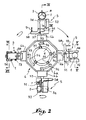
- Fig. 2 est une vue par dessus du mécanisme pour la mise en oeuvre du procédé de positionnement suivant l'invention.
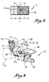
- Fig. 3 est une vue partielle en perspective d'une des pinces du mécanisme de fig. 2.
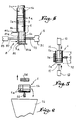
- Fig. 4 montre, en coupe suivant le plan IV-IV de fig. 2, le sélecteur-chargeur de bouchons dans les pinces du mécanisme.
- Fig. 5 illustre la manière dont le bouchon est centré par rapport à la lame ou couteau de chaque pince, suivant le plan de coupe V-V de fig. 2.
- Fig. 6 montre le bouchon en équilibre instable sur la lame ou couteau d'une pince avant sa chute dans l'orientation désirée (coupe suivant VI-VI fr fig. 2).
- Fig. 1 illustrates the structure of a stopper which it is desired to position by applying the method and the mechanism according to the invention.
- Fig. 2 is a view from above of the mechanism for implementing the positioning method according to the invention.
- Fig. 3 is a partial perspective view of one of the clamps of the mechanism of FIG. 2.
- Fig. 4 shows, in section along the plane IV-IV of FIG. 2, the plug selector-loader in the clamps of the mechanism.
- Fig. 5 illustrates the manner in which the plug is centered relative to the blade or knife of each pliers, along the cutting plane VV of FIG. 2.
- Fig. 6 shows the plug in unstable equilibrium on the blade or knife of pliers before it falls into the desired orientation (section along VI-VI fr fig. 2).
On a illustré en coupe en fig. 1, un bouchon 1 destiné par exemple du bouchage d'une bouteille de champagne et qui est réalisé au moyen de deux rondelles de liège 1a collées entre elles et d'un cyclindre 1b réalisé par compression de particules de liège pour obtenir un aggloméré, ledit cylindre étant collé à la dernière rondelle 1a. On comprend aisément qu'un tel article est hétérogène dans le sens de sa longueur, c'est-à-dire que son centre de gravité se trouve hors du plan transversal de symétrie 2 dudit bouchon. Bien entendu, ce centre de gravité G se trouve dans le cylindre 1b qui constitue ainsi un balourd.Illustrated in section in FIG. 1, a
Le mécanisme pour la mise en oeuvre du procédé suivant l'invention, qui a été illustré en fig. 2, comprend essentiellement une goulotte verticale de stockage des bouchons reférencée 3 et dont le diamètre intérieur et légèrement plus grand que celui du bouchon 1. Le mécanisme comporte en outre une tourelle 4 pourvue d'un moyeu 4a de forme polygonale supportant quatre pinces 5 susceptibles de saisir successivement les bouchons à leur sortie de la goulotte 3 et de les amener après trois quarts de tour à leur position d'évacuation dans l'orientation désirée.The mechanism for implementing the method according to the invention, which has been illustrated in FIG. 2, essentially comprises a vertical chute storage REFERENCED
Chaque pince 5 est, comme illustré en fig. 3, composée de deux becs dont l'un 51 constitue une lame ou couteau 52 présentant une arête effilée. Le couteau 52 est solidaire d'un tourillon 53 monté à rotation dans un palier 4b de la tourelle 4 et qui dépasse à l'intérieur de celle-ci qui est formée en réalité par un élément tubulaire. La partie du tourillon 53 dépassant à l'intérieur de la tourelle 4 est assemblée rigidement à l'une des extrémités d'un bras 54 dont l'autre extrémité porte un galet 55 roulant sur une came annulaire fixe 6. L'autre bec de la pince 5 est constitué par un doigt 56 disposé en vis-à-vis du couteau 52 et présentant une largeur notable. Ce doigt est articulé au talon 51 du couteau 52 au moyen d'un axe 57. Un ressort 7 est prévu pour tendre à faire pivoter le doigt 56 en direction du couteau 52. Le doigt 56 comporte encore une queue 58 dont le rôle sera mieux expliqué plus loin.Each
On a illustré en fig. 4 un sélecteur-chargeur 8 situé à la base de la goulotte 3. Il comprend une palette 81 placée à l'extrémité de la tige du piston 82 d'un vérin 83 électrique ou pneumatique. La palette 81 comprend une paroi verticale 81a à partir de la base de laquelle part une oreille horizontale 81b contre laquelle le premier bouchon situé dans la goulotte vient reposer. La partie haute de la paroi 81a est pourvue d'une patte horizontale 81c qui vient obturer la base de la goulotte lorsque le vérin 83 est actionné pour amener le bouchon entre les becs de la pince 5. A ce moment et comme illustré en fig. 2, une rampe 9 illustrée par une flèche agit sur la queue 58 du doigt 56 pour l'écarter du couteau 52 de manière à pouvoir saisir le bouchon orienté verticalement. La rotation de la tourelle 4 entraîne l'échappement de la rampe 9 et la fermeture de la pince qui maintient fermement le bouchon. Lorsque celle-ci arrive au second poste après un trajet angulaire de 90°, une rampe 10 libère très légèrement la pression du doigt 56 sur le bouchon 1 et deux butées 11 sont déplacées par des vérins 12 de manière à centrer le bouchon 1 par rapport au couteau 52. Bien entendu, des cales réglables non représentées sont prévues afin de déterminer exactement les courses des butées 11 en vue de réaliser le centrage précité. Lorsque la pince quitte la seconde position, elle échappe à la rampe 10 et le doigt 56 vient à nouveau appuyer le bouchon contre le couteau 1. La forme de la came annulaire 6 est telle qu'elle communique au bras 54 un mouvement de rotation entraînant celui de la pince qui effectue ainsi une rotation de 90° avant d'arriver à la quatrième position, c'est-àdire celle obtenue après une rotation de 270° à partir de la goulotte 3. Lorsque la pince arrive à cette position, dans laquelle le bouchon est horizontal avec le couteau 52 situé en dessous de lui, une rampe 13 agit sur la queue 58 du doigt 56 pour dégager celui-ci du bouchon qui vient donc comme illustré en fig. 6, en équilibre instable sur le couteau 52. Du fait que sa partie 1b est plus lourde, il tombe dans une trémie 14 dans le sens désiré, c'est-à-dire sa partie 1b en avant. Que le bouchon se présente dans le sens illustré en fig. 6 ou dans le sens contraire avec la partie 1b à gauche, il tombe toujours avec la partie en question la première dans la trémie 14.Illustrated in fig. 4 a selector-
On a ainsi réalisé un mécanisme de positionnement qui permet d'obtenir une distribution dans la trémie 14 à très grande vitesse sans risque d'erreur.A positioning mechanism has thus been produced which makes it possible to obtain distribution in the
Claims (5)
- Method of positioning, in a specific direction, elongate articles (1) of different lengths, that is to say with their centre of gravity situated outside of their cross-sectional plane of symmetry (2), characterised in that it comprises:
pointing the articles (1) successively in a vertical direction;
gripping an article by its lateral wall between the two projection members (52, 56) of a gripper (5), one of the projection members (52) being a knife edge;
centering the article (1) with respect to the knife edge (52) by slightly releasing the gripper (5);
rotating the gripper so as to bring the article (1), which it is holding, into its horizontal position, the knife edge (52) being situated beneath said article;
and opening the gripper (5) so that the article, in an unstable equilibrium on the knife edge, falls vertically in a direction determined by its imbalance. - Mechanism for implementing the method according to claim 1, characterised in that it comprises:
a vertical chute (3) for storing the articles (1);
a selector (8) for the article (1) situated at the base of the chute (3) and being also the means for loading said article (1) into the gripper (5);
a turret-like member (4) provided with a plurality of rotary grippers (5), of which one of the projection members (52) is a knife edge;
a centering means (11, 12) for centering the article (1) with respect to the knife edge (52) of each gripper (5);
ramps (9, 10, 13) suitable for controlling the movements!of the projection members (56) of each gripper (5);
an annular cam (6) for ensuring the rotation of the grippers (5);
a hopper (14), into which the articles fall in the desired direction;
and means for the synchronised control of the various component parts of the mechanism. - Mechanism according to claim 2, characterised in that the knife edge (52) of each gripper (5) is fixed, whereas its opposite projection member or finger (56) is articulated with respect to said knife edge (52), this projection member (56) comprising a spring (7), which causes it to be displaced towards the knife edge (52), as well as a shank (58), which cooperates with the various ramps (9, 10, 13) for controlling the movement of said projection member or finger (56).
- Mechanism according to claim 2, characterised in that the centering of the article is effected through the intermediary of stop members (11), which are supported by means (12) adapted to displace them in a manner appropriate to said centering.
- Mechanism according to claim 2, characterised in that each knife edge (52) is integral with an arm (54), which cooperates with the annular cam (6), thereby imparting to it the desired rotational movement.
Priority Applications (1)
| Application Number | Priority Date | Filing Date | Title |
|---|---|---|---|
| AT89420136T ATE81102T1 (en) | 1988-04-14 | 1989-04-14 | METHOD OF ORIENTING HETEROGENE, LONG OBJECTS IN A PARTICULAR WAY, AND APPARATUS FOR CARRYING OUT THESE. |
Applications Claiming Priority (2)
| Application Number | Priority Date | Filing Date | Title |
|---|---|---|---|
| FR8805189 | 1988-04-14 | ||
| FR8805189A FR2630093B1 (en) | 1988-04-14 | 1988-04-14 | METHOD OF POSITIONING IN A DETERMINED ORIENTATION OF ELONGATED HETEROGENEOUS ARTICLES AND MECHANISMS INTENDED FOR ITS IMPLEMENTATION |
Publications (2)
| Publication Number | Publication Date |
|---|---|
| EP0337906A1 EP0337906A1 (en) | 1989-10-18 |
| EP0337906B1 true EP0337906B1 (en) | 1992-09-30 |
Family
ID=9365465
Family Applications (1)
| Application Number | Title | Priority Date | Filing Date |
|---|---|---|---|
| EP89420136A Expired - Lifetime EP0337906B1 (en) | 1988-04-14 | 1989-04-14 | Process of positioning heterogeneous elongated pieces in a predetermined orientation and mechanism for its implementation |
Country Status (5)
| Country | Link |
|---|---|
| EP (1) | EP0337906B1 (en) |
| AT (1) | ATE81102T1 (en) |
| DE (1) | DE68903022T2 (en) |
| ES (1) | ES2035620T3 (en) |
| FR (1) | FR2630093B1 (en) |
Families Citing this family (4)
| Publication number | Priority date | Publication date | Assignee | Title |
|---|---|---|---|---|
| ATE104640T1 (en) * | 1989-12-04 | 1994-05-15 | Metalprogetti Snc | AUTOMATIC DEVICE FOR LIFTING, TURNING AND DISPATCHING HANGERS WORKING BETWEEN TWO HANGER SYSTEMS PLACED SIDE-BY-SIDE. |
| IT1258041B (en) * | 1992-04-02 | 1996-02-20 | DEVICE SUITABLE FOR STRAIGHTENING CONTAINERS FROM A HORIZONTAL AXIS POSITION TO A VERTICAL AXIS POSITION | |
| US5924545A (en) * | 1996-03-18 | 1999-07-20 | Isi Norgren Inc. | Rotatable shuttle transfer unit |
| DE19704200A1 (en) * | 1997-02-05 | 1998-08-06 | Krupp Kunststofftechnik Gmbh | Device for turning can bodies |
Family Cites Families (3)
| Publication number | Priority date | Publication date | Assignee | Title |
|---|---|---|---|---|
| FR1193495A (en) * | 1957-03-23 | 1959-11-03 | Seitz Werke Gmbh | Cap dispensing device, usable on bottle capping machines |
| FR2110857A5 (en) * | 1971-08-11 | 1972-06-02 | Douillerie Francaise Sa | |
| EP0220214A1 (en) * | 1985-04-26 | 1987-05-06 | STYNER & BIENZ AG | Transfer installation |
-
1988
- 1988-04-14 FR FR8805189A patent/FR2630093B1/en not_active Expired - Lifetime
-
1989
- 1989-04-14 DE DE8989420136T patent/DE68903022T2/en not_active Expired - Fee Related
- 1989-04-14 AT AT89420136T patent/ATE81102T1/en not_active IP Right Cessation
- 1989-04-14 ES ES198989420136T patent/ES2035620T3/en not_active Expired - Lifetime
- 1989-04-14 EP EP89420136A patent/EP0337906B1/en not_active Expired - Lifetime
Also Published As
| Publication number | Publication date |
|---|---|
| FR2630093B1 (en) | 1990-10-19 |
| DE68903022T2 (en) | 1993-07-01 |
| ES2035620T3 (en) | 1993-04-16 |
| EP0337906A1 (en) | 1989-10-18 |
| DE68903022D1 (en) | 1992-11-05 |
| ATE81102T1 (en) | 1992-10-15 |
| FR2630093A1 (en) | 1989-10-20 |
Similar Documents
| Publication | Publication Date | Title |
|---|---|---|
| FR2465665A1 (en) | DEVICE FOR DISTRIBUTING MULTI-FILT CONTAINERS AND MACHINE USING SUCH A DEVICE | |
| EP0477352B2 (en) | Gripping clamp and machine for treating objects, in particular bottles, equipped with said gripping clamp | |
| EP0437501B1 (en) | Machine for the automatic sorting of objects | |
| FR2488169A1 (en) | A SLIDE ASSEMBLY AND A TOOL HOLDER FOR VERTICAL RUN OR ANALOG MACHINE | |
| EP0115989A1 (en) | Method for automatically filling and closing containers, and machine for carrying out the method | |
| EP0286514B1 (en) | Conveyer comprising platforms specially enabling the transport of buckets | |
| EP0337906B1 (en) | Process of positioning heterogeneous elongated pieces in a predetermined orientation and mechanism for its implementation | |
| WO2020254464A1 (en) | Device for gripping products, and method for conveying within an industrial production line | |
| CH441117A (en) | Object transfer mechanism | |
| EP0069011A1 (en) | Apparatus for applying and centering a thermoplastics sleeve around an article by means of a vertical member provided with a floating mandrel | |
| EP0188153B1 (en) | Method and apparatus for filling and dosing flasks | |
| FR2494259A1 (en) | APPARATUS FOR EXTRACTING MOLD FROM CONTAINERS | |
| FR2653301A1 (en) | PROCESS AND DEVICE FOR INDUSTRIAL CLAMPING OF POULTRY. | |
| FR2573006A1 (en) | PRINTING MACHINE | |
| FR2627744A1 (en) | METHOD OF AUTOMATICALLY MANUFACTURING CONTAINERS WITH COVERING LABEL, PARTICULARLY FOR CONTAINERS WITH CYLINDRICAL SECTION AND DEVICE FOR CARRYING OUT SAID METHOD | |
| FR2627411A1 (en) | DEVICE AND METHOD FOR THE AUTOMATIC PLACEMENT OF CLAMP COLLARS | |
| FR2482575A1 (en) | Champagne bottle sealing machine - has bottle positioned while slotted capsule is applied after lifting eye on wire cage | |
| FR2615050A1 (en) | DEVICE FOR POSTING AND CRIMPING BITS ON ELECTRICAL CONDUCTORS | |
| EP0220967A1 (en) | Conveyor for containers | |
| FR2494614A1 (en) | DEVICE FOR LOADING AND UNLOADING PARTS IN A PRODUCTION RECTIFIER MACHINE | |
| FR2667484A1 (en) | Method and machine for topping and tailing plants with elongated bulbs, and in particular shallots | |
| EP1535501A1 (en) | Device for turning over electronic components | |
| EP0268537A1 (en) | Device for the continuous manufacture of sausages and similar products from the conception of the sausages to the tying of their extremities | |
| FR2673922A1 (en) | Method and device for palletising parcels | |
| FR2474002A1 (en) | IMPROVED APPARATUS FOR HANDLING BISCUITS |
Legal Events
| Date | Code | Title | Description |
|---|---|---|---|
| PUAI | Public reference made under article 153(3) epc to a published international application that has entered the european phase |
Free format text: ORIGINAL CODE: 0009012 |
|
| AK | Designated contracting states |
Kind code of ref document: A1 Designated state(s): AT BE CH DE ES FR GB GR IT LI LU NL SE |
|
| 17P | Request for examination filed |
Effective date: 19900327 |
|
| 17Q | First examination report despatched |
Effective date: 19910930 |
|
| RAP1 | Party data changed (applicant data changed or rights of an application transferred) |
Owner name: FRANCOIS VALENTIN SOCIETE DITE |
|
| GRAA | (expected) grant |
Free format text: ORIGINAL CODE: 0009210 |
|
| AK | Designated contracting states |
Kind code of ref document: B1 Designated state(s): AT BE CH DE ES FR GB GR IT LI LU NL SE |
|
| PG25 | Lapsed in a contracting state [announced via postgrant information from national office to epo] |
Ref country code: SE Effective date: 19920930 Ref country code: NL Effective date: 19920930 Ref country code: GR Free format text: LAPSE BECAUSE OF FAILURE TO SUBMIT A TRANSLATION OF THE DESCRIPTION OR TO PAY THE FEE WITHIN THE PRESCRIBED TIME-LIMIT Effective date: 19920930 Ref country code: GB Effective date: 19920930 Ref country code: AT Effective date: 19920930 |
|
| REF | Corresponds to: |
Ref document number: 81102 Country of ref document: AT Date of ref document: 19921015 Kind code of ref document: T |
|
| ITF | It: translation for a ep patent filed | ||
| REF | Corresponds to: |
Ref document number: 68903022 Country of ref document: DE Date of ref document: 19921105 |
|
| NLV1 | Nl: lapsed or annulled due to failure to fulfill the requirements of art. 29p and 29m of the patents act | ||
| GBV | Gb: ep patent (uk) treated as always having been void in accordance with gb section 77(7)/1977 [no translation filed] |
Effective date: 19920930 |
|
| REG | Reference to a national code |
Ref country code: ES Ref legal event code: FG2A Ref document number: 2035620 Country of ref document: ES Kind code of ref document: T3 |
|
| PG25 | Lapsed in a contracting state [announced via postgrant information from national office to epo] |
Ref country code: LU Free format text: LAPSE BECAUSE OF NON-PAYMENT OF DUE FEES Effective date: 19930430 Ref country code: LI Effective date: 19930430 Ref country code: CH Effective date: 19930430 Ref country code: BE Effective date: 19930430 |
|
| PLBE | No opposition filed within time limit |
Free format text: ORIGINAL CODE: 0009261 |
|
| STAA | Information on the status of an ep patent application or granted ep patent |
Free format text: STATUS: NO OPPOSITION FILED WITHIN TIME LIMIT |
|
| 26N | No opposition filed | ||
| BERE | Be: lapsed |
Owner name: FRANCOIS VALENTIN Effective date: 19930430 |
|
| REG | Reference to a national code |
Ref country code: CH Ref legal event code: PL |
|
| PGFP | Annual fee paid to national office [announced via postgrant information from national office to epo] |
Ref country code: FR Payment date: 19950217 Year of fee payment: 7 |
|
| PGFP | Annual fee paid to national office [announced via postgrant information from national office to epo] |
Ref country code: ES Payment date: 19950317 Year of fee payment: 7 |
|
| PGFP | Annual fee paid to national office [announced via postgrant information from national office to epo] |
Ref country code: DE Payment date: 19950518 Year of fee payment: 7 |
|
| PG25 | Lapsed in a contracting state [announced via postgrant information from national office to epo] |
Ref country code: ES Free format text: LAPSE BECAUSE OF NON-PAYMENT OF DUE FEES Effective date: 19960415 |
|
| PG25 | Lapsed in a contracting state [announced via postgrant information from national office to epo] |
Ref country code: FR Effective date: 19961227 |
|
| PG25 | Lapsed in a contracting state [announced via postgrant information from national office to epo] |
Ref country code: DE Effective date: 19970101 |
|
| REG | Reference to a national code |
Ref country code: FR Ref legal event code: ST |
|
| REG | Reference to a national code |
Ref country code: ES Ref legal event code: FD2A Effective date: 19990301 |
|
| PG25 | Lapsed in a contracting state [announced via postgrant information from national office to epo] |
Ref country code: IT Free format text: LAPSE BECAUSE OF NON-PAYMENT OF DUE FEES Effective date: 20050414 |