EP0337801A2 - Justiervorrichtung für Rotationsdruckmaschinen - Google Patents
Justiervorrichtung für Rotationsdruckmaschinen Download PDFInfo
- Publication number
- EP0337801A2 EP0337801A2 EP89303716A EP89303716A EP0337801A2 EP 0337801 A2 EP0337801 A2 EP 0337801A2 EP 89303716 A EP89303716 A EP 89303716A EP 89303716 A EP89303716 A EP 89303716A EP 0337801 A2 EP0337801 A2 EP 0337801A2
- Authority
- EP
- European Patent Office
- Prior art keywords
- cylinder
- shaft
- printing
- bushings
- printing cylinder
- Prior art date
- Legal status (The legal status is an assumption and is not a legal conclusion. Google has not performed a legal analysis and makes no representation as to the accuracy of the status listed.)
- Withdrawn
Links
Images
Classifications
-
- B—PERFORMING OPERATIONS; TRANSPORTING
- B41—PRINTING; LINING MACHINES; TYPEWRITERS; STAMPS
- B41F—PRINTING MACHINES OR PRESSES
- B41F13/00—Common details of rotary presses or machines
- B41F13/08—Cylinders
- B41F13/24—Cylinder-tripping devices; Cylinder-impression adjustments
- B41F13/26—Arrangement of cylinder bearings
- B41F13/28—Bearings mounted eccentrically of the cylinder axis
Definitions
- This invention relates to printing presses of the type in which a printing cylinder is rotated in juxtaposition to a blanket cylinder, and, a substrate to be printed is passed through the nip between the printing cylinder and the blanket cylinder, and an image is impressed thereon by an inked printing plate attached to the printing cylinder.
- the pressure exerted at the pinch of the printing cylinder and the blanket cylinder is sufficient to accommodate the pressures required for accurate printing on a relatively smooth substrate, such as a calendered paper, the pressure is insufficient to accommodate accurate and drop-out free printing onto a heavily textured paper, such as a heavy weight cotton or linen textured paper.
- the task addressed, by the inventor is the provision of adjustment device for a printing cylinder which readily can be adjusted by the press operator in order to provide optimum pressure at the nip of the printing.
- cylinder and the blanket cylinder to accommodate any selected type of substrate, including heavy weight cotton or linen textured paper, in the total absence of "cylinder bounce".
- the use of a spring biasing force to bias the printing cylinder towards the blanket cylinder is eliminated in its entirety, and in its place, the printing cylinder is supported by fixed but adjustable bearings, which can be adjusted by an operator adjustable control, in order to provide a positive pressure at the printing plate which in no way relies upon a spring biasing force, but which instead is produced by the extent of compression of the blanket of the blanket cylinder, and, the extent of compression of the substrate to be printed.
- the operator adjustable control can be operated by the operator to produce an optimum printed image on the substrate throughout the subsequent production run of the printing press, as related to the specific substrate that is being printed.
- the objective of the present invention is accomplished by journaling the support shaft of the printing cylinder in eccentric bushings, which themselves are supported in stationary frame members of the printing press, the bushings being rotatable in unison under the control of an operator actuable mechanism positioned externally of the press.
- a linkage is provided between the operator actuable mechanism and the respective eccentric bushings, in order that a determined angular rotation of a control of the operator actuable mechanism will produce a corresponding angular rotation of each of the respective bushings, and, by virtue of the eccentricity of the mounting of the cylinder support shaft within those bushings, result in a closely controllable adjustment of the printing cylinder towards or away from the blanket cylinder.
- the printing cylinder is adjustable up to the point of direct engagement with the blanket cylinder, but in the absence of compressive engagement therewith, such as would produce "cylinder bounce". Then, in dependence on the thickness of the substrate to be printed, the printing pressure as derived directly from the resistance to compression of the blanket of the blanket cylinder, as opposed to being determined by a spring bias of fixed magnitude as in prior art mechanisms.
- the printing cylinder and its support shaft can be moved towards or away from the blanket cylinder by any amount determined by the operator, either prior to or during a production run, in order to provide optimum pressure at the nip of the printing cylinder and blanket cylinder to produce drop-out free printing of any selected substrate of any particular gauge and of any particular texture, intermediate that of a polished calendered paper and that of coarsely textured cotton or linen textured paper and the like.
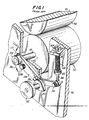
- a printing cylinder indicated generally at 10 is positioned in juxtaposition with a blanket cylinder 12, the blanket cylinder having a resilient coating or blanket 14.
- the respective cylinders are journaled for rotation in parallelism with each other within parallel frames 16 of the printing press, only one of which is shown in Figure 1.
- the printing cylinder 10 is supported for rotation by a shaft 18 which extends through an aperture 20 in the adjacent end frame 16, and projects outwardly of the end frame 16.
- the outwardly extending end of the shaft 18 is received and journaled within a bearing 22 located at one end of a bell crank 24, the bell crank being pivotally connected to the frame member 16 by a stud 26.
- the other arm of the bell crank lever 24 is provided with a laterally extending pin 28, which cooperates with a cam 30, the cam 30 being rotatable under the manual control of an adjustment knob or dial 32.
- a shaft 34 Forwardly of the pin type cam follower 28, that arm of the bell crank lever is connected to a shaft 34 by a connector 36 which permits angular movement of the shaft 34 relative to the end of the bell crank lever 24.
- the shaft 34 extends upwardly through and is slidable within a fixed stop member 38, movement of the shaft 34 being constrained by a compression spring 40 reacting between the fixed stop member 38 and a collar 42 fast with the shaft 34.
- the shaft 34 is threaded, and, lock nuts 44 are threaded thereon for limiting downward movement of the shaft 34.
- the cam 30 is caused to rotate, and, will cause the bell crank 24 to move angularly to raise or lower the longitudinal axis of the shaft 18 in the directions of the arrows 46.
- stop nuts 44 are so set that the cylinder 10 is in sufficiently close proximity to the blanket 14 of the blanket cylinder 12 that a relatively thin substrate, when passed through the nip of the rollers 10 and 14, is sufficiently compressed to assure a drop-out free printing of the substrate by inked printing plates carried on the surface of the printing cylinder 10.
- the pressure exerted on the substrate is determined primarily by the closeness of spacing of the printing cylinder 10 and the blanket cylinder 12, and, will vary in dependence of the gauge or thickness of the substrate fed between the respective cylinders.
- the adjustment of the stop nuts 44 is arranged such that drop-out free printing on the smallest gauge substrate is accomplished, while at the same time the pressure at the nip of cylinders is maintained at an absolute minimum in order to avoid the problem of "cylinder bounce" during rotation of the respective cylinders relative to each other.
- a further consideration is that arising when a heavily textured substrate is to be printed, such is when a heavily textured paper or card is to be printed in a satisfactory manner free of drop-outs.
- the rate of the springs 40 be very considerably increased in order to provide a increased pressure at the nip of the printing and blanket cylinders.
- the spring rate of the springs 40 must be changed in order to secure a change in the pressure exerted at the nip of the cylinders 10 and 14. Without regard to the thickness of the substrate, the pressure at the nip of the cylinders 10 and 14 remains constant, or substantially constant without regard to the extent to which the printing cylinder 10 moves away from the blanket cylinder 14.
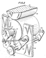
- FIG. 2 there is illustrated a structure embodying the invention by means of which the pressure at the nip of the printing cylinder 10 and blanket cylinder 14 can be adjusted at will under the control of the operator of the press.
- the longitudinal axis of the bearing 50 and which is indicated at 56, is arranged displaced radially of the longitudinal axis of the bushing, and which is indicated at 54, such that the bearing 50 is eccentrically arranged relative to the axis of rotation of the bushing.
- a lug 58 Extending radially of the bushing 52 is a lug 58, to which one end of a push-pull rod 60 is attached, the opposite end of the push-pull rod 60 being connected to a lever 62, the lever 62 being fast with a control shaft 64 rotatable by the control knob 32.
- a simple linkage arrangement has been illustrated for imparting rotational movement to the bushing 52 upon that rotation of the control knob 32, various other drive arrangements could be provided.
- the circumference of the bushing 52 could be in the form of a spur gear, which is meshed with a reciprocatable toothed rack, the toothed rack being movable longitudinally by a spur gear fact with the control shaft 64.
- any convenient drive arrangement could be provided for translating rotational movement of the control knob 32 into a corresponding rotation of the bushing 52.
- a reduction gearing could be provided between the shaft of the control knob 32 and the lever 62 in order to provide a micrometer adjustment of the bushing 52.
- the biassing of the printing cylinder 10 by means of springs has been eliminated in its entirety. Instead, the printing cylinder 10 is movable positively towards or away from the blanket cylinder 12 by a determined extent.
- the blanket 14 of the blanket cylinder 12 itself is formed of a hard but resiliently compressible material, which will provide a cushion for the force exerted by the now fixedly located printed cylinder 10.
- the printing cylinder 10 can be set in an attitude for it to provide drop-out free printing on a substrate of extremely light gauge and having a polished or calendered surface, the extent of the adjustment being readily determinable by the operator during an initial run of the press, i.e., it is simply a matter of adjusting the control 32 to produce the desired quality of printing.
- the extent which the pressure is to be increased will, of course, vary widely in dependence on the extent of texture of the substrate, and, the amount of "give" in the fibers of the substrate. If the substrate is one having a little "give” in the fibers, then, the pressure will have to be increased to an extent greater than that required for a substrate having substantial "give". The amount of "give” will, of course, vary widely between different runs of substrates to be printed, and, there is no accurate way of determining the extent of "give” in any particular substrate.
- the construction embodying the invention provides for an increase in the pressure at the nip of the printing cylinder 10 and blanket cylinder 12 of any desired magnitude, the magnitude of that pressure being under the direct control of the operator of the press.
Landscapes
- Engineering & Computer Science (AREA)
- Mechanical Engineering (AREA)
- Rotary Presses (AREA)
Applications Claiming Priority (2)
| Application Number | Priority Date | Filing Date | Title |
|---|---|---|---|
| US18202988A | 1988-04-15 | 1988-04-15 | |
| US182029 | 1988-04-15 |
Publications (2)
| Publication Number | Publication Date |
|---|---|
| EP0337801A2 true EP0337801A2 (de) | 1989-10-18 |
| EP0337801A3 EP0337801A3 (de) | 1990-06-20 |
Family
ID=22666808
Family Applications (1)
| Application Number | Title | Priority Date | Filing Date |
|---|---|---|---|
| EP89303716A Withdrawn EP0337801A3 (de) | 1988-04-15 | 1989-04-14 | Justiervorrichtung für Rotationsdruckmaschinen |
Country Status (2)
| Country | Link |
|---|---|
| EP (1) | EP0337801A3 (de) |
| JP (1) | JPH0222059A (de) |
Cited By (1)
| Publication number | Priority date | Publication date | Assignee | Title |
|---|---|---|---|---|
| US12168342B2 (en) * | 2021-06-24 | 2024-12-17 | Stolle Machinery Company, Llc | Printing plate pressure adjustment system and can decorator employing same |
Families Citing this family (1)
| Publication number | Priority date | Publication date | Assignee | Title |
|---|---|---|---|---|
| US6339272B1 (en) | 1998-12-24 | 2002-01-15 | Asmo Co., Ltd. | Washer pump and motor brush support structure |
Family Cites Families (4)
| Publication number | Priority date | Publication date | Assignee | Title |
|---|---|---|---|---|
| GB351859A (en) * | 1930-01-16 | 1931-07-02 | Rockstroh Werke Ag | Improvements in and relating to rotary offset printing machines |
| US2160613A (en) * | 1936-11-19 | 1939-05-30 | Goss Printing Press Co Ltd | Rotary printing press |
| DE1113220B (de) * | 1960-04-09 | 1961-08-31 | Roland Offsetmaschf | An- und Abstellvorrichtung fuer Druckmaschinenzylinder |
| US3527165A (en) * | 1967-01-03 | 1970-09-08 | Harris Intertype Corp | Cylinder throw mechanism for printing presses |
-
1989
- 1989-04-14 EP EP89303716A patent/EP0337801A3/de not_active Withdrawn
- 1989-04-14 JP JP1093262A patent/JPH0222059A/ja active Pending
Cited By (1)
| Publication number | Priority date | Publication date | Assignee | Title |
|---|---|---|---|---|
| US12168342B2 (en) * | 2021-06-24 | 2024-12-17 | Stolle Machinery Company, Llc | Printing plate pressure adjustment system and can decorator employing same |
Also Published As
| Publication number | Publication date |
|---|---|
| EP0337801A3 (de) | 1990-06-20 |
| JPH0222059A (ja) | 1990-01-24 |
Similar Documents
| Publication | Publication Date | Title |
|---|---|---|
| EP0105476B1 (de) | Rotationsdruckmaschine | |
| US5301609A (en) | Printing unit with skew and throw-off mechanisms | |
| GB2061459A (en) | Bending rollers | |
| US4676158A (en) | Plate pressure and printing pressure adjusting mechanism for offset printing machine | |
| US5119727A (en) | Inking apparatus for printing press | |
| US2474160A (en) | Ductor roller adjustment and method | |
| US3272122A (en) | Method of adjusting a foreshortened impression roller | |
| US5230284A (en) | Mechanism for adjusting forme rollers at the plate cylinder of a rotary printing machine | |
| US3563173A (en) | Liquid-handling mechanism | |
| US5465663A (en) | Sheet-guiding drum for printing machines | |
| US3888173A (en) | Temperature responsive inking apparatus for a printing machine | |
| US2233895A (en) | Duplicating machine | |
| US5235910A (en) | Blanket cylinder impression throw-off | |
| US3442121A (en) | Device for supervising the ink supply of a printing press | |
| EP0337801A2 (de) | Justiervorrichtung für Rotationsdruckmaschinen | |
| US3368399A (en) | Arrangement for measuring the ink pulling power on lithographic printing machines | |
| US2619901A (en) | Impression length varying means for rotary offset printing machines | |
| US3561359A (en) | Roller adjusting apparatus for a proof press | |
| US5009159A (en) | Printing unit | |
| US5272974A (en) | Offset printing apparatus with printing plate cylinder adjustment | |
| US4488484A (en) | Control device for offset printing cylinders having adjustably mounted eccentric shaft | |
| US5546860A (en) | Device for adjusting distances between axes of cylinders in a printing machine | |
| EP0546029B1 (de) | Offsetdruckmaschine | |
| JPH0259772B2 (de) | ||
| US2778303A (en) | Rotary offset printing press roll support |
Legal Events
| Date | Code | Title | Description |
|---|---|---|---|
| PUAI | Public reference made under article 153(3) epc to a published international application that has entered the european phase |
Free format text: ORIGINAL CODE: 0009012 |
|
| AK | Designated contracting states |
Kind code of ref document: A2 Designated state(s): AT BE CH DE ES FR GB GR IT LI LU NL SE |
|
| PUAL | Search report despatched |
Free format text: ORIGINAL CODE: 0009013 |
|
| AK | Designated contracting states |
Kind code of ref document: A3 Designated state(s): AT BE CH DE ES FR GB GR IT LI LU NL SE |
|
| 17P | Request for examination filed |
Effective date: 19901219 |
|
| STAA | Information on the status of an ep patent application or granted ep patent |
Free format text: STATUS: THE APPLICATION IS DEEMED TO BE WITHDRAWN |
|
| 18D | Application deemed to be withdrawn |
Effective date: 19911105 |