EP0337460A2 - Distributeur de liquides - Google Patents
Distributeur de liquides Download PDFInfo
- Publication number
- EP0337460A2 EP0337460A2 EP89106635A EP89106635A EP0337460A2 EP 0337460 A2 EP0337460 A2 EP 0337460A2 EP 89106635 A EP89106635 A EP 89106635A EP 89106635 A EP89106635 A EP 89106635A EP 0337460 A2 EP0337460 A2 EP 0337460A2
- Authority
- EP
- European Patent Office
- Prior art keywords
- fluid
- pipette
- electronic circuit
- motor
- piston
- Prior art date
- Legal status (The legal status is an assumption and is not a legal conclusion. Google has not performed a legal analysis and makes no representation as to the accuracy of the status listed.)
- Withdrawn
Links
Images


Classifications
-
- B—PERFORMING OPERATIONS; TRANSPORTING
- B01—PHYSICAL OR CHEMICAL PROCESSES OR APPARATUS IN GENERAL
- B01L—CHEMICAL OR PHYSICAL LABORATORY APPARATUS FOR GENERAL USE
- B01L3/00—Containers or dishes for laboratory use, e.g. laboratory glassware; Droppers
- B01L3/02—Burettes; Pipettes
- B01L3/021—Pipettes, i.e. with only one conduit for withdrawing and redistributing liquids
- B01L3/0217—Pipettes, i.e. with only one conduit for withdrawing and redistributing liquids of the plunger pump type
- B01L3/0227—Details of motor drive means
-
- B—PERFORMING OPERATIONS; TRANSPORTING
- B01—PHYSICAL OR CHEMICAL PROCESSES OR APPARATUS IN GENERAL
- B01L—CHEMICAL OR PHYSICAL LABORATORY APPARATUS FOR GENERAL USE
- B01L2300/00—Additional constructional details
- B01L2300/02—Identification, exchange or storage of information
- B01L2300/025—Displaying results or values with integrated means
- B01L2300/027—Digital display, e.g. LCD, LED
Definitions
- the subject of the invention is a fluid dispensing device appropriated for precision measuring of exactly determined dosages of fluid in the course of metering, diluting and titrating.
- the pipette comprises a pipette drive means, including a stepper motor having a stator and a rotor, a control circuit for supplying power to the motor, and a shaft having a threaded connection through the rotor to move in precise lengthwise increments in response to rotation of the rotor; and a displacement assembly, including a displacement chamber and a displacing piston.
- a control circuit means comprising a programmable electronic circcuit, a keyboard, a display and a push-button, as well as the drive means with the stepper motor are integrated into one common casing, whereto the attachable displacement assemblies are secured.
- the said assemblies are of varied volume, being dependable on the size of the displacement chamber.
- Inside each of the assemblies there moves a piston being directly driven from the axis of the rotor.
- the ejection of a measuring tip being each time mounted onto the displacement chamber before drawing in a certain amount of fluid, is carried out be pressing down a push-button of an ejector's assembly of the axis being parallel to the stepper motor's axis and to the fluid displacement assembly's axis.
- the motor and the control circuit are battery-supplied.
- the aim of the present invention is to design a fluid dispensing device comprising a number of pipettes, each of them being light, and to enable easy handling and controlling of the device by a user.
- a dispensing device as per the present invention, being built up of a control unit provided with a programmable electronic circuit, a keyboard and a display, of a drive unit with a motor, of fluid displacement units, each one provided with a cylinder and a piston, and of pipettes each one provided with an ejector's assembly
- the most characteristic is the fact that the control unit, the drive unit and the fluid displacement units are placed into a separate housing, that the motor's shaft is by means of a coupling connected to pistons, that each of the cylinders is connected to its corresponding pipette by means of a flexible electric-pneumatic conduit, comprising conductors and a pneumatic conduit being placed into a common casing, whereas the programmable electronic circuit is provided with a temperature compensation system together with temperature-sensitive elements, one of them being seated inside the said housing, near to the piston.
- Each of the pipettes has a flat hand grip with an opening, suitable for putting the pipette on the user's finger, a detent means for fastening the pipette on the said housing, a swith-key actuating the device, and also a signalling element being controlled from a programmable electronic circuit.
- the device as per the present invention is advantageous be deeplycause by placing the control unit, the drive unit and the fluid displacement units into a separate housing, the pipette becomes light. It enables a free handling therewith, reducing significantly the tiredness of the user's hand. As a result, the efficiency of his work is being increased at enabling a higher comfort for the user.
- the above stated characteristic features of the pipettes, and the fact of simultaneous transmitting of the drive from the motor to the pistons being embodied into particular pipettes, enable a simultaneous usage of the two pipettes by one user.
- the design of the flexible electric-pneumatic conduit, connecting particular pipettes to the fluid displacement units, as well as the application of the temperature compensation system together with the temperature-sensitive elements, ensures a precise transformation of the piston movement into a preset volume of fluid being drawn in by means of a measuring tip. Due to the application of a measuring capillary tube, there has been obtained a possibility of drawing in the minimum dosages of fluid of the volume as below 5 ⁇ l, at simultaneously ensuring a high precision and repeatability of results.
- Fig. 1 is a general view of the device together with the two pipettes
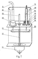
- Fig. 2 is a partial cross-sectional view of a drive unit and of fluid displacement units
- Fig. 3 is a cross-sectional view of a flexible electric-pneumatic conduit
- Fig. 4 is a wiring diagram of the device
- Fig. 5 is a side view of the pipette comprising an ejector's assembly of a measuring capillary tube.
- the device is built up of a control unit, a drive unit and fluid displacement units, being placed into a housing 1 , end of pipettes 2 , being connected to the said control unit and to the said fluid displacement unit by means of flexible electric-pneumatic conduits 3 .
- Outside housing 1 in its front wall, there is a display 4 together with a keyboard 5 , being meant for presetting the device.
- Each of pipettes 2 is provided with a switch-key 6 actuating the device, a push-button 7 of an ejector's assembly, enabling a measuring tip 8 to be released from a clamping sleeve 9 , and also a signalling element 10 which signals the realization stage of the programme.
- the drive unit of the device consists of a motor 11 , whose screw shaft 12 performs reciprocating movements.
- a coupling 13 with pistons 14 being secured thereto.
- Pistons 14 move inside cylinders 15 and are sealed by means of a sleeve 16 , being placed inside a rubber ring 17 .
- Sleeve 16 together with ring 17 , is fitted into the lower part of cylinder 15 by means of a nut 18 and of a washer 19 .
- Cylinders 15 are mounted onto the upper arm of a channel 20 , and are placed inside a metal casing 21 .
- To the lower arm of channel 20 there is secured a stator of motor 11 .
- a vertical guide 22 in the form of a rod which is being displaced into a bearing 23 which is fitted onto the upper arm of channel 20 .
- the lower end of guide 22 is secured to coupling 13 .
- a pneumatic conduit 24 Onto the upper narrowed end of each of the cylinders 15 , there is mounted a pneumatic conduit 24 , which together with conductors 25 forms a flexible electron-pneumatic conduit 3 , connecting the control unit, which is placed in housing 1 , to particular pipettes 2 .
- Said pneumatic conduit 24 and conductors 25 are encased into a common casing 26 in such a manner that they form an integral part therewith.
- the control unit of the device is built up of a programmable electronic circuit 27 , a display 4 and a keyboard 5 , being supplied from a power supply source.
- the said unit controls the operation of motor 11 , while it is itself being controlled by means of keyboard 5 and of pipettes 2 .
- the programmable electronic circuit 27 has a temperature compensation system 28 provided with two temperature-sensitive elements, i.e. thermistors 29 and 30 .
- Thermistor 29 is seated inside housing 1 , near to piston 14 whereas the other thermistor is also seated inside housing 1 , into a bracket serving to embed pipette 2 .
- Each of pipettes 2 has a flat grip 31 with an opening 32 which serves for putting pipette 2 on a user's finger, and a detent means 33 for fitting pipette 2 on housing 1 .
- a signalling element 10 On the side surface of hand grip 31 there is a signalling element 10 , wherein an electroluminescent diode is installed, being controlled from a programmable electronic circcuit 27 .
- a switch-key 6 actualing the device, a push-button 7 of an ejector's assembly and also a flexible electric-pneumatic conduit 3 .
- pipette 2 In its lower part, pipette 2 is provided with a clamping sleeve 9 with a measuring tip 8 being attached thereto.
- Programmable electronic circuit 27 into the control unit of the device is ready for performing the operation cycle after being preset from keyboard 5 .
- the information being stored into the device is shown on display 4 .
- the operation cycle of the device starts at the moment when swith-key 6 is actuated at one of pipettes 2 . Then the drive unit of the device is activated and screw shaft 12 of motor 11 performs an advance movement downwards.
- pistons 14 are moved downwards, said pistons being placed in cylinders 15 .
- a verticular guide 22 moving in a bearing 23 enables a simultaneous movement of piston 14 inside cylinders 15 .
- the movement of pistons 14 in the first stage of operation of the device, causes the fluid be sucked through a pneumatic conduit 24 and pipette 2 to measuring tip 8 .
- That hand grip 31 of pipette 2 is being held by the user.
- screw shaft 12 of motor 11 performs an advance movement upwards, pistons 14 being placed in cylinders 15 move upwards, and via pneumatic conduit 24 and via pipette 2 cause dispensing the drawn-in fluid from measuring tip 8 .
- measuring tip 8 is being ejected with the aid of push-button 7 of the ejector's assembly.
- the realization stage of the program is being signalled by a signalling element 10 which is placed into the side surface of hand grip 31 of each of pipettes 2 . In this way, drawing in and dispensing of fluid is being signalled.
- the electric signals coming from electronic circuit 27 to signalling element 10 , and from switch-key 6 which activates the device, are being transmitted by means of conductors 25 .
- Temperature compensation system 28 together with two thermistors 29 and 30 , one of which being placed near to piston 14 in the area being shielded with metal casing 21 , whereas the other one being placed into the bracket appropriated for mounting pipette 2 , ensures a full correction of volume changes of the fluid being drawn in, dependably on the difference between the temperature prevailing near to piston 14 and in the ambient air.
- Temperature compensation system 28 being a part of the unit which controls the device, ensures the foreseen precision in drawing in and in dispensing the portions of fluid.
Applications Claiming Priority (2)
| Application Number | Priority Date | Filing Date | Title |
|---|---|---|---|
| PL271846 | 1988-04-15 | ||
| PL1988271846A PL152191B1 (en) | 1988-04-15 | 1988-04-15 | A fluid dispensing device |
Publications (2)
| Publication Number | Publication Date |
|---|---|
| EP0337460A2 true EP0337460A2 (fr) | 1989-10-18 |
| EP0337460A3 EP0337460A3 (fr) | 1990-06-27 |
Family
ID=20041630
Family Applications (1)
| Application Number | Title | Priority Date | Filing Date |
|---|---|---|---|
| EP89106635A Withdrawn EP0337460A3 (fr) | 1988-04-15 | 1989-04-13 | Distributeur de liquides |
Country Status (6)
| Country | Link |
|---|---|
| US (1) | US4976161A (fr) |
| EP (1) | EP0337460A3 (fr) |
| CS (1) | CS227289A3 (fr) |
| DD (1) | DD283778A5 (fr) |
| HU (1) | HUT49717A (fr) |
| PL (1) | PL152191B1 (fr) |
Cited By (6)
| Publication number | Priority date | Publication date | Assignee | Title |
|---|---|---|---|---|
| WO1997002893A1 (fr) * | 1995-07-07 | 1997-01-30 | Biohit Oy | Procede de correction d'une erreur de distribution de liquide et dispositif de distribution de liquide |
| FR2862889A1 (fr) * | 2003-11-27 | 2005-06-03 | Gilson Sas | Pipette a main pour le prelevement d'un echantillon liquide sans derive de temperature |
| JP2008203009A (ja) * | 2007-02-19 | 2008-09-04 | Hitachi High-Technologies Corp | 自動分析装置 |
| US7976793B2 (en) | 2003-11-27 | 2011-07-12 | Gilson S.A.S. | Electronic pipette |
| US8117928B2 (en) | 2006-04-25 | 2012-02-21 | Biohit Oyj | Method for selecting a pipette tip and a device for implementation |
| DE102019126731A1 (de) * | 2019-10-02 | 2021-04-08 | Hamilton Bonaduz Ag | Vorrichtung und Verfahren zum exakten flüssigkeitsklassen-unabhängigen Pipettieren |
Families Citing this family (3)
| Publication number | Priority date | Publication date | Assignee | Title |
|---|---|---|---|---|
| WO2005085775A1 (fr) * | 2004-02-06 | 2005-09-15 | Seyonic S.A. | Dispositif de verification de pipette et pipette |
| US8899118B1 (en) * | 2009-05-11 | 2014-12-02 | Dan Seguin | Multi-channel aspirating and dispensing instrument |
| WO2013062580A1 (fr) * | 2011-10-28 | 2013-05-02 | Hewlett-Packard Development Company, L.P. | Procédé d'adressage parallèle |
Citations (4)
| Publication number | Priority date | Publication date | Assignee | Title |
|---|---|---|---|---|
| DE2261645A1 (de) * | 1972-12-16 | 1974-06-20 | Brand Fa Rudolf | Vorrichtung zum genauen abmessen kleiner fluessigkeitsmengen |
| JPS57147060A (en) * | 1981-03-09 | 1982-09-10 | Toshiba Corp | Apparatus for automatic chemical analysis |
| EP0070571A2 (fr) * | 1981-07-21 | 1983-01-26 | BAXTER INTERNATIONAL INC. (a Delaware corporation) | Commande pour distributeur de liquide automatisé |
| US4598840A (en) * | 1983-10-11 | 1986-07-08 | Burg Donald E | Snap-in cartridge diluter |
Family Cites Families (6)
| Publication number | Priority date | Publication date | Assignee | Title |
|---|---|---|---|---|
| US3915651A (en) * | 1972-09-22 | 1975-10-28 | Us Government | Direct digital control pipette |
| US4101283A (en) * | 1976-07-13 | 1978-07-18 | Karl Erik Sundstrom | Disposable reagent container and actuation mechanism |
| US4475666A (en) * | 1981-08-31 | 1984-10-09 | American Hospital Supply Corporation | Automated liquid dispenser control |
| US4671123A (en) * | 1984-02-16 | 1987-06-09 | Rainin Instrument Co., Inc. | Methods and apparatus for pipetting and/or titrating liquids using a hand held self-contained automated pipette |
| US4779467A (en) * | 1987-01-28 | 1988-10-25 | Rainin Instrument Co., Inc. | Liquid-end assembly for multichannel air-displacement pipette |
| US4821586A (en) * | 1988-02-25 | 1989-04-18 | Medical Laboratory Automation, Inc. | Programmable pipette |
-
1988
- 1988-04-15 PL PL1988271846A patent/PL152191B1/pl unknown
-
1989
- 1989-04-12 CS CS892272A patent/CS227289A3/cs unknown
- 1989-04-13 EP EP89106635A patent/EP0337460A3/fr not_active Withdrawn
- 1989-04-13 US US07/337,576 patent/US4976161A/en not_active Expired - Fee Related
- 1989-04-14 DD DD89327651A patent/DD283778A5/de not_active IP Right Cessation
- 1989-04-17 HU HU891873A patent/HUT49717A/hu unknown
Patent Citations (4)
| Publication number | Priority date | Publication date | Assignee | Title |
|---|---|---|---|---|
| DE2261645A1 (de) * | 1972-12-16 | 1974-06-20 | Brand Fa Rudolf | Vorrichtung zum genauen abmessen kleiner fluessigkeitsmengen |
| JPS57147060A (en) * | 1981-03-09 | 1982-09-10 | Toshiba Corp | Apparatus for automatic chemical analysis |
| EP0070571A2 (fr) * | 1981-07-21 | 1983-01-26 | BAXTER INTERNATIONAL INC. (a Delaware corporation) | Commande pour distributeur de liquide automatisé |
| US4598840A (en) * | 1983-10-11 | 1986-07-08 | Burg Donald E | Snap-in cartridge diluter |
Non-Patent Citations (2)
| Title |
|---|
| AUTOMATIE, vol. 15, no. 2, February 1971, pages 45-49, Baarn, NL; "Testrapport: dosseer- en verdunningsapparatuur van Ahrend" * |
| PATENT ABSTRACTS OF JAPAN, vol. 6, no. 248 (P-160)[1126], 7th December 1982; & JP-A-57 147 060 (TOKYO SHIBAURA DENKI K.K.) * |
Cited By (10)
| Publication number | Priority date | Publication date | Assignee | Title |
|---|---|---|---|---|
| WO1997002893A1 (fr) * | 1995-07-07 | 1997-01-30 | Biohit Oy | Procede de correction d'une erreur de distribution de liquide et dispositif de distribution de liquide |
| US5895838A (en) * | 1995-07-07 | 1999-04-20 | Biohit Oy | Method for correcting a liquid dispensing error, and a liquid dispensing device |
| FR2862889A1 (fr) * | 2003-11-27 | 2005-06-03 | Gilson Sas | Pipette a main pour le prelevement d'un echantillon liquide sans derive de temperature |
| EP1541975A1 (fr) * | 2003-11-27 | 2005-06-15 | Gilson S.A.S. | Pipette à main pour le prélèvement d'un échantillon liquide sans dérive de température |
| WO2005053848A1 (fr) * | 2003-11-27 | 2005-06-16 | Gilson Sas | Pipette a main pour le prelevement d'un echantillon liquide sans derive de temperature |
| US7976793B2 (en) | 2003-11-27 | 2011-07-12 | Gilson S.A.S. | Electronic pipette |
| US8117928B2 (en) | 2006-04-25 | 2012-02-21 | Biohit Oyj | Method for selecting a pipette tip and a device for implementation |
| JP2008203009A (ja) * | 2007-02-19 | 2008-09-04 | Hitachi High-Technologies Corp | 自動分析装置 |
| EP1959259A3 (fr) * | 2007-02-19 | 2009-08-26 | Hitachi High-Technologies Corporation | Analyseur automatique |
| DE102019126731A1 (de) * | 2019-10-02 | 2021-04-08 | Hamilton Bonaduz Ag | Vorrichtung und Verfahren zum exakten flüssigkeitsklassen-unabhängigen Pipettieren |
Also Published As
| Publication number | Publication date |
|---|---|
| HUT49717A (en) | 1989-10-30 |
| PL271846A1 (en) | 1989-11-13 |
| US4976161A (en) | 1990-12-11 |
| DD283778A5 (de) | 1990-10-24 |
| PL152191B1 (en) | 1990-11-30 |
| CS227289A3 (en) | 1992-08-12 |
| EP0337460A3 (fr) | 1990-06-27 |
Similar Documents
| Publication | Publication Date | Title |
|---|---|---|
| US4821586A (en) | Programmable pipette | |
| US4475666A (en) | Automated liquid dispenser control | |
| EP0337460A2 (fr) | Distributeur de liquides | |
| US6601433B2 (en) | Hand-held pipette | |
| EP1750842B1 (fr) | Pipette a main | |
| US4528161A (en) | Probe for automated liquid dispenser | |
| JP5706086B2 (ja) | 手持ち式ピペット装置 | |
| US9623406B2 (en) | Electronic pipette | |
| KR20020087411A (ko) | 복귀 스프링이 없는 인체공학적 수동 공기 변위 피펫 | |
| EP0576967A2 (fr) | Pipette motorisée | |
| EP0199452A1 (fr) | Pipette de volume variable | |
| US20020174687A1 (en) | Method and apparatus for pulling multibarrel pipettes | |
| US7146867B2 (en) | Proportioning device | |
| WO2006028399A1 (fr) | Dispositif de pipettage electronique pour aspirer et distribuer des volumes de liquide determines | |
| US4230001A (en) | Tatooing pincers for marking ears of animals | |
| AU2004294757A1 (en) | Hand-held pipette for taking a liquid sample without temperature drift | |
| JP5880911B2 (ja) | 分注装置等におけるシリンダユニット | |
| KR20050071484A (ko) | 피펫 캘리브레이션 방법 | |
| EP0070571A2 (fr) | Commande pour distributeur de liquide automatisé | |
| US11229905B2 (en) | Method and apparatus for dispensing precise aliquots of liquid | |
| US20030182968A1 (en) | Apparatus for pulling multibarrel pipettes | |
| FI109882B (fi) | Pipetti | |
| PL186037B1 (pl) | Sposób kalibracji pipety | |
| CN116106236A (zh) | 注液装置及医疗设备 | |
| PL151372B1 (pl) | Pipeta automatyczna ze sterownikiem mikroprocesorowym |
Legal Events
| Date | Code | Title | Description |
|---|---|---|---|
| PUAI | Public reference made under article 153(3) epc to a published international application that has entered the european phase |
Free format text: ORIGINAL CODE: 0009012 |
|
| AK | Designated contracting states |
Kind code of ref document: A2 Designated state(s): DE FR GB |
|
| PUAL | Search report despatched |
Free format text: ORIGINAL CODE: 0009013 |
|
| AK | Designated contracting states |
Kind code of ref document: A3 Designated state(s): DE FR GB |
|
| 17P | Request for examination filed |
Effective date: 19900920 |
|
| 17Q | First examination report despatched |
Effective date: 19911227 |
|
| STAA | Information on the status of an ep patent application or granted ep patent |
Free format text: STATUS: THE APPLICATION IS DEEMED TO BE WITHDRAWN |
|
| 18D | Application deemed to be withdrawn |
Effective date: 19921203 |