EP0337380A2 - Halbleiter-Druckwandler - Google Patents
Halbleiter-Druckwandler Download PDFInfo
- Publication number
- EP0337380A2 EP0337380A2 EP89106383A EP89106383A EP0337380A2 EP 0337380 A2 EP0337380 A2 EP 0337380A2 EP 89106383 A EP89106383 A EP 89106383A EP 89106383 A EP89106383 A EP 89106383A EP 0337380 A2 EP0337380 A2 EP 0337380A2
- Authority
- EP
- European Patent Office
- Prior art keywords
- tube
- plug
- plate
- fluid
- transducer
- Prior art date
- Legal status (The legal status is an assumption and is not a legal conclusion. Google has not performed a legal analysis and makes no representation as to the accuracy of the status listed.)
- Granted
Links
- 239000004065 semiconductor Substances 0.000 title abstract description 5
- 239000011521 glass Substances 0.000 claims abstract description 5
- 238000010438 heat treatment Methods 0.000 claims abstract description 4
- 239000012530 fluid Substances 0.000 claims description 19
- 238000000034 method Methods 0.000 claims description 9
- 239000000463 material Substances 0.000 claims description 4
- 230000004888 barrier function Effects 0.000 claims description 3
- 238000004519 manufacturing process Methods 0.000 description 6
- 230000002093 peripheral effect Effects 0.000 description 2
- RZVAJINKPMORJF-UHFFFAOYSA-N Acetaminophen Chemical compound CC(=O)NC1=CC=C(O)C=C1 RZVAJINKPMORJF-UHFFFAOYSA-N 0.000 description 1
- OKTJSMMVPCPJKN-UHFFFAOYSA-N Carbon Chemical compound [C] OKTJSMMVPCPJKN-UHFFFAOYSA-N 0.000 description 1
- 239000004593 Epoxy Substances 0.000 description 1
- 229910052799 carbon Inorganic materials 0.000 description 1
- 238000001816 cooling Methods 0.000 description 1
- PCHJSUWPFVWCPO-UHFFFAOYSA-N gold Chemical compound [Au] PCHJSUWPFVWCPO-UHFFFAOYSA-N 0.000 description 1
- 239000010931 gold Substances 0.000 description 1
- 229910052737 gold Inorganic materials 0.000 description 1
- 239000005297 pyrex Substances 0.000 description 1
- MAKDTFFYCIMFQP-UHFFFAOYSA-N titanium tungsten Chemical compound [Ti].[W] MAKDTFFYCIMFQP-UHFFFAOYSA-N 0.000 description 1
- 238000003466 welding Methods 0.000 description 1
Images
Classifications
-
- G—PHYSICS
- G01—MEASURING; TESTING
- G01L—MEASURING FORCE, STRESS, TORQUE, WORK, MECHANICAL POWER, MECHANICAL EFFICIENCY, OR FLUID PRESSURE
- G01L19/00—Details of, or accessories for, apparatus for measuring steady or quasi-steady pressure of a fluent medium insofar as such details or accessories are not special to particular types of pressure gauges
- G01L19/14—Housings
- G01L19/147—Details about the mounting of the sensor to support or covering means
-
- G—PHYSICS
- G01—MEASURING; TESTING
- G01L—MEASURING FORCE, STRESS, TORQUE, WORK, MECHANICAL POWER, MECHANICAL EFFICIENCY, OR FLUID PRESSURE
- G01L19/00—Details of, or accessories for, apparatus for measuring steady or quasi-steady pressure of a fluent medium insofar as such details or accessories are not special to particular types of pressure gauges
- G01L19/0007—Fluidic connecting means
- G01L19/0038—Fluidic connecting means being part of the housing
Definitions
- the present invention relates to absolute pressure transducers and specifically, is directed to a method for making an absolute pressure transducer and a transducer made thereby.
- An object of the present invention is to provide an improved method for manufacturing an absolute pressure transducer.
- Another object of the present invention is to provide an improved absolute pressure transducer.
- a further object of the present invention is to provide an improved pressure transmitter using the improved pressure transducer.
- a method for making an absolute pressure transducer including the steps of mounting a strain responsive plate having strain-sensitive elements supported thereon across one end of an electrically insulating tube to form a first fluid-tight seal therewith, inserting a loose plug of a material similar to the material of the tube within the tube to define a chamber exposed to the plate, exposing the interior of the tube to a vacuum, concurrently heating the tube in the vicinity of the plug to allow the heated tube wall to fuse with the plug to form a second fluid-tight seal therewith and allowing the tube and plug to cool to trap the vacuum in the chamber.
- a pressure transmitter uses the transducer with electrical connections to the strain-sensitive elements in a fluid filled system for applying an external pressure to the plate to produce an output signal from the strain-sensitive elements representative of the differential pressure between the evacuated chamber and the external pressure.
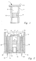
- an absolute pressure transducer 1 using a semiconductor plate or diaphragm 2 having strain-sensitive elements, e.g., piezoresistive diffused therein.
- the plate 2 is mounted across an open end of an electrically insulating tube 4, e.g., Pyrex, by conventional means.
- the plate 2 may be attached by first metallizing the end of the tube 4, e.g., using a titanium-tungsten and gold layering process, and subsequently providing a thermal-electron bond of the plate 2 to the metallized surface.
- the plate 2 is wider than the outer diameter of the tube 4 and the aforesaid mounting provides a first fluid-tight seal across the tube 4.
- a plug 6 is located within the bore of the tube 4 to define a chamber 8 within the tube 4 adjacent to the plate 2.
- the tube 4 has a constricted wall 10 in the vicinity of the plug 6 as a result of the assembly of the transducer 1 as discussed hereinafter.
- the constricted portion 10 of the wall 4 is bonded or fused to the plug 6 to form a second fluid-tight seal therewith to define a chamber 8 exposed to the plate 2.
- the chamber 8 is arranged to be an evacuated chamber to provide a reference pressure for the plate 2. Accordingly, the transducer 1 shown in Fig. 1 provides a response which is occasioned by the pressure differential between the evacuated chamber 8 and a pressure applied externally to the other side of the plate or diaphragm 2.
- FIG. 2 there is shown a mounting or header for supporting the transducer 1 shown in Fig. 1. Similar reference numbers have been used in Fig. 2 to indicate elements common to the illustration of Fig. 1.
- the header shown in Fig. 2 includes an outer metallic shell 12 having an inner axial chamber 14 for accommodating the transducer 1 shown in Fig. 1.
- An open end of the tube 4 opposite to the plate 2 is held within the chamber 14 by a Rollpin 16 extending between the tube 4 and a counter bore 18 within the shell 12 at the bottom of the well 14.
- a pair of through holes 20 and 22 are provided through the shell 12 on respective sides of the well 14.
- a pair of metallic electrically conductive pins 24,26 are located in respective ones of the holes 20,22.
- the pins 24,26 are provided with a fluid-tight seal to the internal wall of the holes 20,22 by respective glass seals 28,30 extending therebetween.
- the pins 24,26 provide electrical connections through the shell 12.
- Electrical wires 32,34 are connected between the ends of the pins 24,26 adjacent to the plate 2 to provide electrical connections to the strain-sensitive elements diffused in the plate 2.
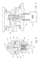
- FIG. 3 there is shown a pressure transmitter utilizing the header and transducer assembly shown in Fig. 2.
- the pressure transmitter shown in Fig. 3 includes a pair of coaxial housings 40,42 which are attached together by any suitable means (not shown).
- a first one of the housings 40 includes a cavity 44 arranged to accommodate the header 12 therein.
- the outer peripheral surface of the header 12 is attached to the inner wall of the cavity 44 by any suitable means to provide a fluid-tight seal, e.g., epoxy bonding, welding, etc.
- the header 12 is arranged to expose the outer surface of the plate 2 to the remaining interior volume of the cavity 44.
- a fluid passage or duct 46 is provided within the housing 40 and extends from the bottom of the cavity 44 to the surface of a concave depression 48 located in a surface of a housing 40.
- the second housing 42 is provided with a threaded hole 50 for accommodating a threaded connection to a fluid inlet pipe (not shown).
- An internal fluid passage 52 is provided between the threaded hole 50 and a concave surface on a surface of the second housing 42.
- the first and second concave surfaces 48,54 are arranged in a facing coaxial relationship and are separated by a flexible diaphragm 56.
- the diaphragm 56 and the first surface 48 define a first fluid volume 58
- the diaphragm 56 and the second surface 54 define a second fluid volume 60.
- the flexible diaphragm 56 is provided with a fluid-tight seal between its outer peripheral edge and the housing 40,42 by any suitable means, e.g., O-ring 62.
- a first fill fluid is provided within the first housing 40 and provides a fluid path from one side of the diaphragm 56 through the first volume 58 and the fluid channel 46 to the cavity 44 and the outer surface of the plate 2.
- An external fluid for applying a pressure to be sensed to the transmitter shown in Fig. 3 is used to fill the fluid volume defined by the threaded bore 50, the fluid channel 52 and the second volume 60 to the other side of the barrier diaphragm 56.
- an external pressure applied via the external fluid is effective to act on the barrier diaphragm 56 to transmit a similar pressure through the fill fluid within the first housing 40 to the plate 2 to produce an output signal from the strain-sensitive elements diffused in the plate 2.
- An output signal from the plate 2 is derived via the wires 32,34, the pins 24,26 and external electrical connections 60,62 attached thereto.
- Fig. 4 there is shown a pictorial illustration of an apparatus for manufacturing the transducer shown in Fig. 1.
- a vacuum source 70 e.g., a vacuum pump
- a pair of tube holders 72,74 are used to hold the tube 4 and to provide a heat sink to protect the integrity of the plate 2.
- the open end of the tube 4 is sealed to one end of a hollow plunger 76 by an O-ring 78.
- the other end of the plunger 76 is connected by a pipe 80 to the vacuum source 70.
- a hollow carbon rod 82 rests on the end of the plunger 76 adjacent to the O-ring 78 and extends into the tube 4 to provide a locating support for the glass plug 6.
- a gas jet 84 is used to heat the plug 6 and the tube 4 in the vicinity of the plug 6 to produce the constricted surface 10 of the tube 4 to trap the plug 6 and fuse the tube 4 therewith. After cooling, the tube assembly forming the transducer 1 is removed from the clamps 72,74 and utilized as described above.
Landscapes
- Physics & Mathematics (AREA)
- General Physics & Mathematics (AREA)
- Chemical & Material Sciences (AREA)
- Analytical Chemistry (AREA)
- Measuring Fluid Pressure (AREA)
- Pressure Sensors (AREA)
Applications Claiming Priority (2)
| Application Number | Priority Date | Filing Date | Title |
|---|---|---|---|
| US18176988A | 1988-04-15 | 1988-04-15 | |
| US181769 | 1988-04-15 |
Publications (3)
| Publication Number | Publication Date |
|---|---|
| EP0337380A2 true EP0337380A2 (de) | 1989-10-18 |
| EP0337380A3 EP0337380A3 (de) | 1991-07-03 |
| EP0337380B1 EP0337380B1 (de) | 1993-09-08 |
Family
ID=22665717
Family Applications (1)
| Application Number | Title | Priority Date | Filing Date |
|---|---|---|---|
| EP89106383A Expired - Lifetime EP0337380B1 (de) | 1988-04-15 | 1989-04-11 | Halbleiter-Druckwandler |
Country Status (4)
| Country | Link |
|---|---|
| EP (1) | EP0337380B1 (de) |
| JP (1) | JP2645588B2 (de) |
| CA (1) | CA1320847C (de) |
| DE (1) | DE68908934T2 (de) |
Cited By (1)
| Publication number | Priority date | Publication date | Assignee | Title |
|---|---|---|---|---|
| CN116380330A (zh) * | 2023-05-31 | 2023-07-04 | 成都凯天电子股份有限公司 | 一种用于高温的无液体压阻式碳化硅压力传感器 |
Family Cites Families (3)
| Publication number | Priority date | Publication date | Assignee | Title |
|---|---|---|---|---|
| JPS5242517B2 (de) * | 1972-10-11 | 1977-10-25 | ||
| US4106349A (en) * | 1977-11-03 | 1978-08-15 | Kulite Semiconductor Products, Inc. | Transducer structures for high pressure application |
| JPS5543819A (en) * | 1978-09-22 | 1980-03-27 | Hitachi Ltd | Pressure detecting equipment |
-
1989
- 1989-04-11 EP EP89106383A patent/EP0337380B1/de not_active Expired - Lifetime
- 1989-04-11 DE DE1989608934 patent/DE68908934T2/de not_active Expired - Lifetime
- 1989-04-14 CA CA000596746A patent/CA1320847C/en not_active Expired - Lifetime
- 1989-04-14 JP JP9509689A patent/JP2645588B2/ja not_active Expired - Lifetime
Cited By (2)
| Publication number | Priority date | Publication date | Assignee | Title |
|---|---|---|---|---|
| CN116380330A (zh) * | 2023-05-31 | 2023-07-04 | 成都凯天电子股份有限公司 | 一种用于高温的无液体压阻式碳化硅压力传感器 |
| CN116380330B (zh) * | 2023-05-31 | 2023-10-24 | 成都凯天电子股份有限公司 | 一种用于高温的无液体压阻式碳化硅压力传感器 |
Also Published As
| Publication number | Publication date |
|---|---|
| DE68908934D1 (de) | 1993-10-14 |
| HK1008091A1 (en) | 1999-04-30 |
| JP2645588B2 (ja) | 1997-08-25 |
| EP0337380B1 (de) | 1993-09-08 |
| DE68908934T2 (de) | 1994-06-01 |
| JPH02203231A (ja) | 1990-08-13 |
| CA1320847C (en) | 1993-08-03 |
| EP0337380A3 (de) | 1991-07-03 |
Similar Documents
| Publication | Publication Date | Title |
|---|---|---|
| US5948988A (en) | Pressure transducer with flame arrester | |
| JP3476199B2 (ja) | 高圧隔離マウント組立体を有する圧力トランスミッタ | |
| US7762139B2 (en) | Pressure transducer apparatus adapted to measure engine pressure parameters | |
| US6938490B2 (en) | Isolation technique for pressure sensing structure | |
| CA1077294A (en) | Pressure transmitter with simplified pressure sensing head | |
| US6561038B2 (en) | Sensor with fluid isolation barrier | |
| JPH0374937B2 (de) | ||
| JP3987386B2 (ja) | 圧力センサ | |
| US6120033A (en) | Process diaphragm seal | |
| US20120118069A1 (en) | Pressure transducer assembly having an integral back-up ring | |
| EP0677727A2 (de) | Druckwandler-Montage und Herstellungsverfahren dazu | |
| US5847282A (en) | Piezoresistive pressure sensor or pressure detector assembly | |
| US6058780A (en) | Capacitive pressure sensor housing having a ceramic base | |
| CN109642844A (zh) | 用于减少压力测量室的容积的填充体 | |
| US4888992A (en) | Absolute pressure transducer and method for making same | |
| US6591686B1 (en) | Oil filled pressure transducer | |
| US6324914B1 (en) | Pressure sensor support base with cavity | |
| JPH0665974B2 (ja) | 圧力センサユニツトの製造方法 | |
| EP0337380B1 (de) | Halbleiter-Druckwandler | |
| HK1008091B (en) | Semiconductor pressure sensor | |
| CN118339439A (zh) | 用于确定介质的第一压力的相对压力测量记录器 | |
| JPS5822933A (ja) | 耐圧防爆形絶対圧力変換器 | |
| JP2984420B2 (ja) | 差圧センサ | |
| US4361047A (en) | Differential pressure to electrical signal transducer | |
| RU2054616C1 (ru) | Способ изготовления герметизированных тензорезисторов |
Legal Events
| Date | Code | Title | Description |
|---|---|---|---|
| PUAI | Public reference made under article 153(3) epc to a published international application that has entered the european phase |
Free format text: ORIGINAL CODE: 0009012 |
|
| AK | Designated contracting states |
Kind code of ref document: A2 Designated state(s): DE FR GB IT |
|
| PUAL | Search report despatched |
Free format text: ORIGINAL CODE: 0009013 |
|
| AK | Designated contracting states |
Kind code of ref document: A3 Designated state(s): DE FR GB IT |
|
| 17P | Request for examination filed |
Effective date: 19911209 |
|
| 17Q | First examination report despatched |
Effective date: 19921028 |
|
| GRAA | (expected) grant |
Free format text: ORIGINAL CODE: 0009210 |
|
| AK | Designated contracting states |
Kind code of ref document: B1 Designated state(s): DE FR GB IT |
|
| REF | Corresponds to: |
Ref document number: 68908934 Country of ref document: DE Date of ref document: 19931014 |
|
| ET | Fr: translation filed | ||
| ITF | It: translation for a ep patent filed | ||
| PLBE | No opposition filed within time limit |
Free format text: ORIGINAL CODE: 0009261 |
|
| STAA | Information on the status of an ep patent application or granted ep patent |
Free format text: STATUS: NO OPPOSITION FILED WITHIN TIME LIMIT |
|
| 26N | No opposition filed | ||
| REG | Reference to a national code |
Ref country code: GB Ref legal event code: IF02 |
|
| PGFP | Annual fee paid to national office [announced via postgrant information from national office to epo] |
Ref country code: GB Payment date: 20080317 Year of fee payment: 20 |
|
| PGFP | Annual fee paid to national office [announced via postgrant information from national office to epo] |
Ref country code: DE Payment date: 20080430 Year of fee payment: 20 |
|
| PGFP | Annual fee paid to national office [announced via postgrant information from national office to epo] |
Ref country code: IT Payment date: 20080419 Year of fee payment: 20 |
|
| PGFP | Annual fee paid to national office [announced via postgrant information from national office to epo] |
Ref country code: FR Payment date: 20080403 Year of fee payment: 20 |
|
| REG | Reference to a national code |
Ref country code: GB Ref legal event code: PE20 Expiry date: 20090410 |
|
| PG25 | Lapsed in a contracting state [announced via postgrant information from national office to epo] |
Ref country code: GB Free format text: LAPSE BECAUSE OF EXPIRATION OF PROTECTION Effective date: 20090410 |