EP0337089A1 - Implement for cutting silage with U-shaped cutting-member - Google Patents
Implement for cutting silage with U-shaped cutting-member Download PDFInfo
- Publication number
- EP0337089A1 EP0337089A1 EP89103236A EP89103236A EP0337089A1 EP 0337089 A1 EP0337089 A1 EP 0337089A1 EP 89103236 A EP89103236 A EP 89103236A EP 89103236 A EP89103236 A EP 89103236A EP 0337089 A1 EP0337089 A1 EP 0337089A1
- Authority
- EP
- European Patent Office
- Prior art keywords
- cutting
- support frame
- cutter according
- end arms
- silage
- Prior art date
- Legal status (The legal status is an assumption and is not a legal conclusion. Google has not performed a legal analysis and makes no representation as to the accuracy of the status listed.)
- Ceased
Links
Images


Classifications
-
- A—HUMAN NECESSITIES
- A01—AGRICULTURE; FORESTRY; ANIMAL HUSBANDRY; HUNTING; TRAPPING; FISHING
- A01F—PROCESSING OF HARVESTED PRODUCE; HAY OR STRAW PRESSES; DEVICES FOR STORING AGRICULTURAL OR HORTICULTURAL PRODUCE
- A01F25/00—Storing agricultural or horticultural produce; Hanging-up harvested fruit
- A01F25/16—Arrangements in forage silos
- A01F25/20—Unloading arrangements
- A01F25/2027—Unloading arrangements for trench silos
- A01F25/2036—Cutting or handling arrangements for silage blocks
-
- Y—GENERAL TAGGING OF NEW TECHNOLOGICAL DEVELOPMENTS; GENERAL TAGGING OF CROSS-SECTIONAL TECHNOLOGIES SPANNING OVER SEVERAL SECTIONS OF THE IPC; TECHNICAL SUBJECTS COVERED BY FORMER USPC CROSS-REFERENCE ART COLLECTIONS [XRACs] AND DIGESTS
- Y10—TECHNICAL SUBJECTS COVERED BY FORMER USPC
- Y10S—TECHNICAL SUBJECTS COVERED BY FORMER USPC CROSS-REFERENCE ART COLLECTIONS [XRACs] AND DIGESTS
- Y10S83/00—Cutting
- Y10S83/928—Vehicle-mounted tool
-
- Y—GENERAL TAGGING OF NEW TECHNOLOGICAL DEVELOPMENTS; GENERAL TAGGING OF CROSS-SECTIONAL TECHNOLOGIES SPANNING OVER SEVERAL SECTIONS OF THE IPC; TECHNICAL SUBJECTS COVERED BY FORMER USPC CROSS-REFERENCE ART COLLECTIONS [XRACs] AND DIGESTS
- Y10—TECHNICAL SUBJECTS COVERED BY FORMER USPC
- Y10T—TECHNICAL SUBJECTS COVERED BY FORMER US CLASSIFICATION
- Y10T83/00—Cutting
- Y10T83/929—Tool or tool with support
- Y10T83/9454—Reciprocable type
Definitions
- the invention relates to a silage crop cutter with a U-shaped support frame that can be attached to a mounting frame and can be moved vertically up and down on its rigid support frame legs, on both sides of which rigid support frame legs are designed, which are designed as knife-shaped, rigid cutting strips and can be moved in opposite directions by drive mechanisms.
- Silage crop cutters are used for the block-shaped cutting of silage, especially from flat silos.
- Silage crop cutters are mostly used as attachments for agricultural tractors or other similar vehicles and, on the one hand, have to ensure that the highest possible cutting performance is achieved by the drive element (s) on the cutting bars.
- the silage cutter should be as light as possible in order to enable the highest possible payload of silage.
- silage crop cutters are designed in such a way that, in order to produce an exact cut in the silage crop, the cutting tools on the lateral support frame legs as well as on the front cutting mechanism are either designed as simple cutting strips which are laterally on the front side of the side legs of the support frame Cut out the attached working cylinder by saw-like pulling the cutting strips back and forth, the cutting strips of the front cutting unit being connected to the side cutting units via flexible corner connecting elements.
- the cutting tools are double cutting tools, one cutting bar being rigidly mounted and the other being pulled back and forth in opposite directions.
- the driving force is generated via a single working element attached to the front support frame leg, the vertical movement of the working cylinder being converted into horizontal knife bar movements via a connecting element and lever arms.
- the tractive force is transferred from the front cutting bars to the side cutting bars via angle levers and other levers.
- the object of the invention is to enable a weight-saving, low-maintenance and as effective as possible direct transmission of the thrust power of the drive elements to the cutting strips and to be able to do without the implementation of vertically acting thrust force in horizontally acting tensile force by the knife strips by means of complex lever technology.
- This object is achieved according to the invention in that the driving force of two working cylinders, each attached to the end of the fork-shaped fastening devices of the lateral support frame legs on the mounting frame, acts as a thrust force on two lever arms which are fixed to the cutting direction and which can move back and forth to the cutting direction lever arms, which are vertically superimposed on each other and which are transmitted to a rigid center piece of side cutting tools.
- the stacking of the end arms of the cutting tools is made possible by the fact that the inner cutting strips are generally higher than the outer cutting strips. This makes it possible to have the end arms angled one above the other towards the center.
- the end arms of the side cutting strips pointing towards the front leg of the support frame are in turn superimposed and in turn transfer the thrust force to the respectively assigned end arms of the front cutting unit via two corner connecting elements.
- the design of the corner connecting elements is designed so that in a guide part leading around the corner in an arcuate manner, in two planes arranged upright one above the other, for better intermeshing one-sided arc-shaped milled metal cylindrical rollers, the thrust through the end arm of the front element penetrating into the upper and lower level of the corner connecting element or rear side cutting bar is transferred to the associated end arm of the front cutting bars.
- a chain or steel strip-like configuration can also be provided for the power transmission in the guide part as the power transmission means.
- the weight of the silage cutter can be reduced.
- the counter-rotation of the cutting bars of the individual cutting tools and a narrower design of the cutting tools due to the design contribute to an increased cutting force of the silage crop cutting device.
- Attaching the working cylinders outside the actual cutting area of the silage crop cutter has an advantageous effect when working. This attachment also enables the pressure line to be laid outside the cutting area.
- a U-shaped support frame is shown in a perspective view, the front of the fork-shaped construction parts 5, which are firmly connected to fixed central webs 7 of the side and front leg of the support frame, each on the central webs by guide bolts 10 in guide grooves 9 6 and rear 8 knife-shaped cutting strips, which are non-positively connected to one another at their end arms 12 via corner connecting elements 11.
- the cutting strips 6 and 8 are attached to each other at the end of the fork-shaped construction parts 5, which produce the connection of the support frame to the mounting frame 18, counter-working drive cylinders 15 by means of drive pistons 16 via drive levers which can be moved back and forth in the fork-shaped construction parts 5 by articulated bolts 2 1 set in horizontal opposite movement.
- the drive pistons 16 of the working cylinders 15 are each coupled to the drive levers 1 via a connecting joint 3.
- FIG. 2 shows in cross section a drive lever 1, which is of the same type in the fork-shaped construction parts 5, which establish the connection to the mounting frame 18, about a pivot pin 2 that is permanently installed on the latter.
- the drive lever is connected by means of a connecting joint 3 to the corresponding drive piston 16 (FIG. 1) of the respective working cylinder (FIG. 1/15).
- the front 6 and rear 8 cutting strips of the side cutting tools are connected to the drive levers 1 by means of bearing bolts 4 which are placed on pins and welded to the drive lever 1.
- Figure 3 shows a side view of the operation of a drive lever 1.
- the drive lever is movable about a rigid joint 2. It is connected to the drive piston of the working cylinder via a connecting joint 3.
- the respective front 6 and rear 8 cutting bar of the side cutting tools are movably connected by the hinge pins 4, which each protrude into the joint socket 4a of the cutting bars.
- FIG. 4 shows the mode of operation of a corner connecting element in a horizontal section Guide device 11a of the corner connecting element 11, which is guided in an arc around the corner, engages the cutting bar arms 12, which transmit the driving force to one another by means of reciprocal thrust by means of upright metal cylinder rollers which are milled out on one side for better intermeshing.
- the cutting strips 6 and 8 are bent at their ends so that they are angled towards the center in such a way that the end arms, each one above the other, can engage in the two planes of the corner connecting element, one above the other.
- FIG. 5 shows the mode of operation of the corner connecting elements 11 in a side view.
- the ndarme 12 of the front 6 and rear 8 cutting strips engage in the superimposed guide devices 11a and transmit the drive pressure via the interlocking metal cylindrical rollers around the corner.
- Figure 6 shows in cross section the structure of a cutting tool.
- the front cutting bar 6 and the rear cutting bar 8 are held parallel to one another by means of a pin 10 welded to the fixed central web 7 of the supporting frame.
- the guide pin 10 has at its ends a projecting head 10a, which engage in a fitting manner in the guide grooves 9 milled on the cutting strips and thereby ensure accurate, flutter-free guidance of the cutting strips.
- FIG. 7 shows a side view of a cutting tool, the front cutting bar 6, which is parallel to one another, and the rear cutting bar 8, each being held in a guide groove on the fixed central web 7 by means of a bolt 10.
- the cutting bars can be moved horizontally back and forth with respect to this fixed bolt up to the respective outer stop 9a of the guide groove.
Landscapes
- Life Sciences & Earth Sciences (AREA)
- Environmental Sciences (AREA)
- Threshing Machine Elements (AREA)
- Storage Of Harvested Produce (AREA)
- Harvester Elements (AREA)
Abstract
Die Erfindung betrifft ein Silagegutschneidegerät mit einem an einem Montagegetell anbringbaren und an diesem vertikal auf- und abbewegbaren U-förmigen Tragrahmen, an dessen starren Tragrahmenschenkeln beidseitig, von Antriebsorganen gegenläufig bewegbare, als messerförmige, starre Schneidleisten ausgebildete Schneidwerkzeuge gehaltert sind.The invention relates to a silage cutter with a U-shaped support frame that can be attached to an assembly table and can be moved vertically up and down on the rigid support frame legs, on both sides of which rigid support frame legs, cutting tools designed as knife-shaped, rigid cutting strips, can be moved in opposite directions.
Das neue Gerät kennzeichnet sich dadruch, daß zur Übertragung der Antriebskraft von zwei endseitig am Tragrahmenende angebrachten Antriebsorganen zwei um jeweils feststehende Gelenkbolzen in Schneidebewegungsrichtung vor- und zurückbewegliche Hebel vorgesehen sind, über die übereinanderliegend und einander übergreifend ausgestalteten Endarme (12) der an einem starren Mittelstück (7) gehalterten Schneideleisten (6, 8) der Seitenschneidwerkzeuge auf diese übertragen wird, die jeweils an ihrem anderen Ende auf ihren Endarmen (12) in die ihnen zugeordnete Ebene von Eckverbindungselementten (11) eingreifend, über die in diesen befindlichen Krafübertragungsmittel (13) die Kraft auf die jeweiligen Endarme (12) der vorderen Scheidleisten (6, 8) übertragen. Bevorzugt ist dabei vorgesehen, daß die Übertragungsmittel (13) aus in einem Führungsgehause aufrecht stehenden, mittels einseitig eingefräster bogenförmiger Nuten ineinandergreifenden, Schubkräfte übertragenden Metallzylinderrollen bestehen. 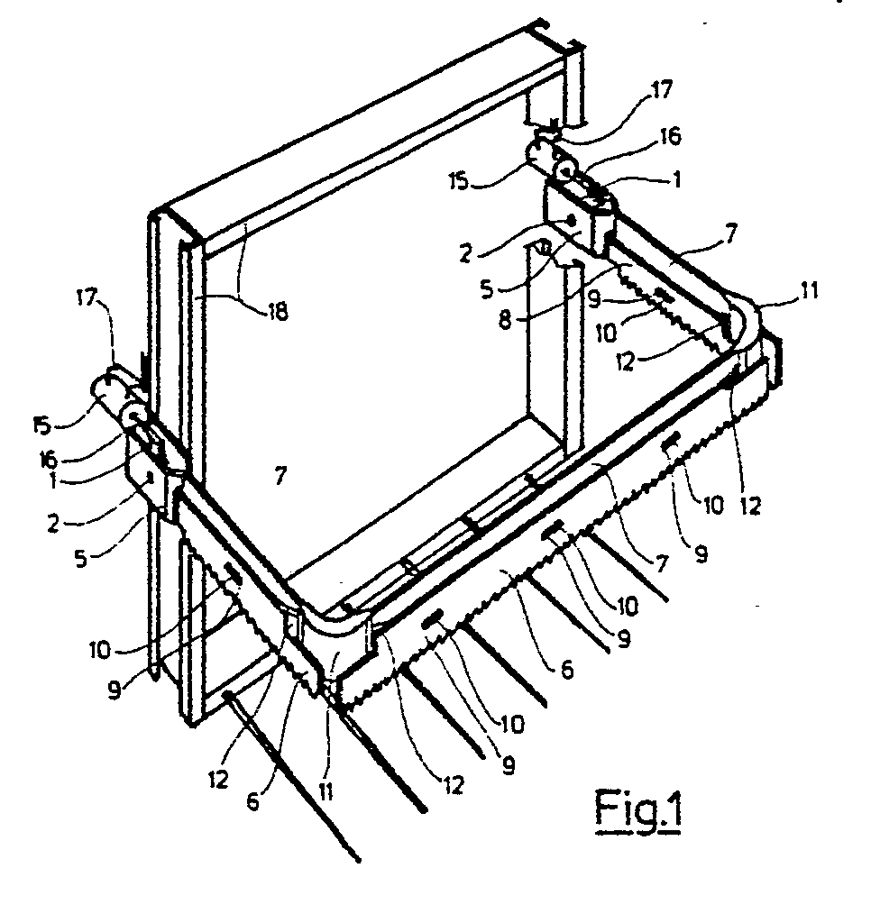
Description
Die Erfindung betrifft ein Silagegutschneidegerät mit einem an einem Montagegestell anbringbaren und an diesem vertikal auf- und abbewegbaren U-förmigen Tragrahmen, an dessen starren Tragrahmenschenkeln beidseitig, von Antriebsorgangen gegenläufig bewegbare, als messerförmige, starre Schneidleisten ausgebildete Schneidwerkzeuge gehaltert sind.The invention relates to a silage crop cutter with a U-shaped support frame that can be attached to a mounting frame and can be moved vertically up and down on its rigid support frame legs, on both sides of which rigid support frame legs are designed, which are designed as knife-shaped, rigid cutting strips and can be moved in opposite directions by drive mechanisms.
Silagegutschneidegeräte dienen dem blockförmigen Ausschneiden von Silagegut insbesondere aus Flachsilos. Silagegutschneidegeräte werden zumeist als Anbaugeräte für Ackerschlepper oder andere ähnliche Fahrzeuge eingesetzt und müssen dabei einerseits gewährleisten, daß möglichst hohe Schneidleistung von dem oder den Antriebsorganen auf die Schneidleisten gebracht wird. Zum anderen soll der Silagegutschneider wegen des vorgegebenen zulässigen Gesamtgewichts des Schleppfahrzeuges von möglichst geringem Eigengewicht sein, um eine möglichst hohe Nutzlast an Silagegut zu ermöglichen.Silage crop cutters are used for the block-shaped cutting of silage, especially from flat silos. Silage crop cutters are mostly used as attachments for agricultural tractors or other similar vehicles and, on the one hand, have to ensure that the highest possible cutting performance is achieved by the drive element (s) on the cutting bars. On the other hand, due to the predetermined permissible total weight of the towing vehicle, the silage cutter should be as light as possible in order to enable the highest possible payload of silage.
Herkömmlicherweise sind Silagegutschneidegeräte so ausgebildet, daß zur Erzeugung eines exakten Schnitts im Silagegut die Schneidwerkzeuge an den seitlichen Tragrahmenschenkeln wie auch am Frontschneidewerk entweder als einfache Schneidleisten ausgebildet sind, die durch seitlich an der Stirnendseite der Seitenschenkel des Tragegestells angebrachte Arbeitszylinder durch sägeartiges Hin- und Herziehen der Schneidleisten den Silageblock herausschneiden, wobei die Schneidleisten des Frontschneidewerkes mit den Seitenschneidewerken über flexible Eckverbindungselemente verbunden sind.Conventionally, silage crop cutters are designed in such a way that, in order to produce an exact cut in the silage crop, the cutting tools on the lateral support frame legs as well as on the front cutting mechanism are either designed as simple cutting strips which are laterally on the front side of the side legs of the support frame Cut out the attached working cylinder by saw-like pulling the cutting strips back and forth, the cutting strips of the front cutting unit being connected to the side cutting units via flexible corner connecting elements.
Auch ist bekannt, die Schneidewerkzeuge als Doppelschneidewerkzeuge auszubilden, wobei eine Schneidleiste starr montiert und die andere hierzu gegenläufig hin- und hergezogen wird. Auch wird teilweise die Antriebskraft über ein einziges, auf dem Fronttragrahmenschenkel angebrachtes Arbeitsorgan erzeugt, wobei die vertikale Bewegung vom Arbeitszylinder über ein Verbindungselement sowie Hebelarme in horizontale Messerleistenbewegungen umgesetzt wird. Hierbei wird die Zugkraft über Winkelhebel und weitere Hebel von den Frontschneideleisten auf die Seitenschneideleisten übertragen.It is also known to design the cutting tools as double cutting tools, one cutting bar being rigidly mounted and the other being pulled back and forth in opposite directions. In some cases, the driving force is generated via a single working element attached to the front support frame leg, the vertical movement of the working cylinder being converted into horizontal knife bar movements via a connecting element and lever arms. The tractive force is transferred from the front cutting bars to the side cutting bars via angle levers and other levers.
Diese Ausgestaltung setzt eine konstruktiv aufwendige, störanfällige und gewichtserhöhende Konstruktion voraus. Nachteilig wirkt sich hierbei aus, daß Antriebsorgan sowie Druckmittelleitungen im Arbeitsbereich des Schneidegerätes angebracht werden müssen.This configuration requires a structurally complex, fault-prone and weight-increasing construction. The disadvantage here is that the drive element and pressure medium lines must be attached in the working area of the cutting device.
Aufgabe der Erfindung ist es, eine gewichtssparende, wartungsarme und möglichst effektive direkte Übertragung der Schubleistung der Antriebsorgane auf die Schneidleisten zu ermöglichen und auf die Umsetzung von vertikal wirkender Schubkraft in horizontal wirkende Zugkraft den den Messerleisten mittels aufwendiger Hebeltechnik verzichten zu können. Diese Aufgabe ist erfindungsmäßig dadurch gelöst, daß die Antriebskraft von zwei jeweils am Ende der gabelförmig ausgestalteten Befestigungsvorrichtungen der seitlichen Tragrahmenschenkel am Montagegestell angebrachten Arbeitszylinder als Schubkraft über zwei um festinstallierte Gelenkbolzen jeweils zur Schneiderichtung hin und her beweglichen Hebelarme auf die jeweils vertikal übereinander gelagerten Hebelarme der an einem starren Mittelstück gehalterten Seitenschneidwerkzeuge übertragen wird.The object of the invention is to enable a weight-saving, low-maintenance and as effective as possible direct transmission of the thrust power of the drive elements to the cutting strips and to be able to do without the implementation of vertically acting thrust force in horizontally acting tensile force by the knife strips by means of complex lever technology. This object is achieved according to the invention in that the driving force of two working cylinders, each attached to the end of the fork-shaped fastening devices of the lateral support frame legs on the mounting frame, acts as a thrust force on two lever arms which are fixed to the cutting direction and which can move back and forth to the cutting direction lever arms, which are vertically superimposed on each other and which are transmitted to a rigid center piece of side cutting tools.
Das Übereinanderlegen der Endarme der Schneidwerkzeuge wird dadurch ermöglicht, daß die inneren Schneideleisten insgesamt höher als die äußeren Schneideleisten ausgebildet sind. Dadurch ist es möglich, die Endarme zur Mitte hin abgewinkelt übereinander verlaufen zu lassen.The stacking of the end arms of the cutting tools is made possible by the fact that the inner cutting strips are generally higher than the outer cutting strips. This makes it possible to have the end arms angled one above the other towards the center.
Dadurch das der jeweils obere Endarm der Seitenschneideleisten mit dem oberen Arm der Antriebshebel verbunden ist, der untere, jeweils in Gegenrichtung zum oberen Arm des Antriebshebels befindlich, mit dem unteren Endarm der Seitenschneideleisten verbunden ist, wird eine gegenläufige Schneidleistenbewegung ermöglicht.As a result of the fact that the upper end arm of the side cutting strips is connected to the upper arm of the drive lever, the lower one, which is located in the opposite direction to the upper arm of the drive lever, is connected to the lower end arm of the side cutting strips, an opposite cutting strip movement is made possible.
Die an ihren zum Frontschenkel des Tragrahmens hinweisenden Endarme der Seitenschneideleisten sind wiederum übereinander gelagert ausgestaltet und führen ihrerseits über zwei Eckverbindungselemente die Schubkraft auf die jeweilig zugeordneten Endarme des Frontschneidewerks über.The end arms of the side cutting strips pointing towards the front leg of the support frame are in turn superimposed and in turn transfer the thrust force to the respectively assigned end arms of the front cutting unit via two corner connecting elements.
Dabei ist die Ausgestaltung der Eckverbindungselemente so konzipiert, daß in einem bogenförmig um die Ecke führenden Führungsteil in zwei Ebenen übereinander aufrecht angeordnete, zum besseren Ineinandergreifen einseitig bogenförmig ausgefräste Metallzylinderrollen die Schubkraft durch den jeweils in die obere bzw. untere Ebene des Eckverbindungselementes eindringenden Endarm der vorderen bzw. hintern Seitenschneideleiste auf den jeweils zugeordneten Endarm der Frontschneideleisten übertragen wird.The design of the corner connecting elements is designed so that in a guide part leading around the corner in an arcuate manner, in two planes arranged upright one above the other, for better intermeshing one-sided arc-shaped milled metal cylindrical rollers, the thrust through the end arm of the front element penetrating into the upper and lower level of the corner connecting element or rear side cutting bar is transferred to the associated end arm of the front cutting bars.
Dabei können zur Kraftübertragung im Führungsteil als Kraftübertragungsmittel auch eine ketten- oder stahlbandähnliche Ausgestaltung vorgesehen werden.A chain or steel strip-like configuration can also be provided for the power transmission in the guide part as the power transmission means.
Auch ist eine Ausbildung der Führungsteile der Eckverbindungselemente als Hydraulikteile denkbar, wobei die Endarme der Schneidleisten dann kolbenförmig auszugestalten wären und Hydraulikflüssigkeit als Kraftmittler eingesetzt werden könnte.It is also conceivable to design the guide parts of the corner connecting elements as hydraulic parts, the end arms of the cutting strips then being designed in the form of a piston and hydraulic fluid being able to be used as a force transmitter.
Die mit der Erfindung erzielbaren Vorteile liegen insbesondere darin, daß die Antriebskraft der horizontal arbeitenden Arbeitszylinder als Schubkraft ohne Kraftverlust mittels Hebeln direkt auf die Schneidleisten übertragbar ist.The advantages that can be achieved with the invention are, in particular, that the driving force of the horizontally operating working cylinders can be transmitted directly to the cutting bars as thrust force without loss of force by means of levers.
Das Ersetzten der aufwendigen Hebelkonstruktionen sowie insbesondere die Verwendung der erfindungsgemäßen, den Arbeitsdruck übertragenden Eckverbindungselemente anstelle flexibler oder winkelhebelförmiger Eckverbindungen ermöglicht das Vermeiden von Kraftverlust in den Übertragungsbereichen sowie störanfälligen Konstruktionsaufwand.The replacement of the elaborate lever constructions and, in particular, the use of the corner connecting elements according to the invention, which transmit the working pressure instead of flexible or angle lever-shaped corner connections, makes it possible to avoid loss of power in the transmission areas and to avoid construction work prone to failure.
Durch Verminderung der Anzahl konstruktionsbedingter Teile kann das Gewicht des Silagegutschneidegeräts reduziert werden.By reducing the number of construction-related parts, the weight of the silage cutter can be reduced.
Die Gegenläufigkeit der Schneidleisten der einzelnen Schneidwerkzeuge sowie eine konstruktionsbedingt schmalere Ausführung der Schneidwerkzeuge tragen zu einer erhöhten Schneidkraft des Silagegutschneidegerätes bei.The counter-rotation of the cutting bars of the individual cutting tools and a narrower design of the cutting tools due to the design contribute to an increased cutting force of the silage crop cutting device.
Vorteilhaft beim Arbeitseinsatz wirkt sich das Anbringen der Arbeitszylinder außerhalb des eigentlichen Schneidebereichs des Silagegutschneidegerätes aus. Diese Anbringung ermöglicht ebenfalls ein Verlegen der Druckleitung außerhalb des Schneidbereichs.Attaching the working cylinders outside the actual cutting area of the silage crop cutter has an advantageous effect when working. This attachment also enables the pressure line to be laid outside the cutting area.
Eine Ganzummantelung des Tragrahmens einschließlich aller beweglicher Teile, bis auf die unterseits herausragenden Messerschneiden, gewährleistet geringe Störanfälligkeit durch Verschmutzung.A complete covering of the support frame including all moving parts, except for the knife edges protruding on the underside, ensures low susceptibility to faults due to pollution.
Ein Ausführungsbeispiel ist in den Zeichnungen dargestellt und wird im folgenden näher beschrieben. Es zeigen:
Figur 1 eine perspektivische Ansicht des Silagegutschneidegerätes mit U-förmigem MontagegestellFigur 2 einen Querschnitt durch einen Antriebshebel in Höhe des Gelenkbolzens (2) inFigur 1- Figur 3 eine Seitenansicht des in
Figur 2 im Querschnitt dargestellten Antriebshebels Figur 4 einen horizontalen Schnitt durch ein Eckverbindungselement und die zugehörigen Endarme eines Seiten- bzw. FrontschneidewerkzeugesFigur 5 die Seitenansicht eines EckverbindungselementesFigur 6 die Darstellung eines Schneidewerkzeuges im Querschnitt im Bereich eines Führungsbolzens (Schnittebene A - A der Figur 7)Figur 7 die Seitenansicht eines Schneidewerkzeuges im Bereich eines Führungsbolzens.
- Figure 1 is a perspective view of the silage cutter with U-shaped mounting frame
- Figure 2 shows a cross section through a drive lever at the level of the hinge pin (2) in Figure 1
- Figure 3 is a side view of the drive lever shown in cross section in Figure 2
- Figure 4 shows a horizontal section through a corner connecting element and the associated end arms of a side or front cutting tool
- Figure 5 is a side view of a corner connector
- 6 shows the representation of a cutting tool in cross section in the area of a guide pin (cutting plane A - A of FIG. 7)
- Figure 7 is a side view of a cutting tool in the area of a guide pin.
In der Figur 1 ist in perspektivischer Ansicht ein U-förmiger Tragrahmen dargestellt, der aus gabelförmigen Konstruktionsteilen 5, die mit feststehenden Mittelstegen 7 der Seiten- sowie des Frontschenkels des Tragrahmens fest verbunden sind, jeweils an den Mittelstegen durch Führungsbolzen 10 in Führungsnuten 9 gehalterten vorderen 6 und hinteren 8 messerartig ausgebildeten Schneidleisten besteht, die an deren Endarme 12 über Eckverbindungselemente 11 miteinander kraftschlüssig verbunden sind.In Figure 1, a U-shaped support frame is shown in a perspective view, the front of the fork-
Die Schneidleisten 6 und 8 werden über ein jeweils am Ende der gabelförmigen Konstruktionsteile 5, die die Verbindung des Tragrahmens zum Montagegestell 18 herstellen, angebrachte, gegenläufig arbeitende Antriebszylinder 15 mittels Antriebskolben 16 über jeweils in den gabelförmigen Konstruktionsteilen 5 um Gelenkbolzen 2 vor- und zurückbewegbare Antriebshebel 1 in horizontal gegenläufige Bewegung versetzt.The
Dabei sind die Antriebskolben 16 der Arbeitszylinder 15 jeweils über ein Verbindungsgelenk 3 mit den Antriebshebeln 1 gekoppelt.The
Figur 2 stellt im Querschnitt einen Antriebshebel 1 dar, der in jeweils gleichartiger Ausführung in den gabelförmig ausgebildeten Konstruktionsteilen 5, die die Verbindung zum MOntagegestell 18 herstellen, um einen an diesen festinstallierten Gelenkbolzen 2 beweglich ist. Der Antriebshebel ist mittels eines Verbindungsgelenks 3 mit dem entsprechenden Antriebskolben 16 (Figur 1) der jeweiligen Arbeitszylinder (Figur 1/15) verbunden. Durch auf Zapfen aufgesetzte, mit dem Antriebshebel 1 fest verschweißte Lagerbolzen 4 sind die vorderen 6 und hinteren 8 Schneidleisten der Seitenschneidwerkzeuge mit den Antriebshebeln 1 verbunden.FIG. 2 shows in cross section a
Figur 3 stellt in Seitenansicht die Arbeitsweise eines Antriebshebels 1 dar. Der Antriebshebel ist um ein starres Gelenk 2 beweglich. Er ist über ein Verbindungsgelenk 3 mit dem Antriebskolben des Arbeitszylinders verbunden. Die jeweils vordere 6 und hintere 8 Schneidleiste der Seitenschneidwerkzeuge sind durch die Gelenkbolzen 4, die mit ihrem jeweils überstehenden Teil in die Gelenkpfannen 4a der Schneidleisten eingreifen, beweglich verbunden.Figure 3 shows a side view of the operation of a
Figur 4 stellt in einem horizontalen Schnitt die Wirkungsweise eines Eckverbindungselementes dar. In die Führungsvorrichtung 11a des bogenförmig um die Ecke geführten Eckverbindungselementes 11 greifen die Schneidleistenarme 12 ein, die mittels aufrechtstehender, zum besseren Ineinandergreifen einseitig bogenförmig ausgefräster Metallzylinderrollen die Antriebskraft jeweils mittels wechselseitigen Schubes aufeinander übertragen.FIG. 4 shows the mode of operation of a corner connecting element in a horizontal
Dabei ist ersichtlich, daß die Schneidleisten 6 und 8 an ihrem Ende so zur Mitte hin winkelförmig abgebogen sind, daß die Endarme jeweils in einer Ebene übereinander gelagert in den beiden Ebenen des Eckverbindungselementes eingreifen können.It can be seen that the
Figur 5 stellt die Wirkungsweise der Eckverbindungselemente 11 in Seitenansicht dar. Dabei greifen die ndarme 12 der vorderen 6 und hinteren 8 Schneidleisten in die übereinandergelagerten Führungsvorrichtungen 11a ein und leiten den Antriebsdruck über die ineinandergreifenden Metallzylinderrollen um die Ecke herum weiter.FIG. 5 shows the mode of operation of the
Figur 6 zeigt im Querschnitt den Aufbau eines Schneidwerkzeuges. Dabei ist im Bereich eines Führungsbolzens 9 die vordere Schneidleiste 6 und die hintere Schneidleiste 8 zueinander parallel mittels eines an dem feststehenden Mittelsteg 7 des Tragrahmens festverschweißten bolzens 10 gehaltert. Der Führungsbolzen 10 weist an seinen Enden jeweils einen überkragenden Kopf 10a auf, der paßgerecht in die an den Schneidleisten eingefrästen Führungsnuten 9 eingreifen und dadurch für eine genaue, flatterfreie Führung der Schneidleisten Sorge tragen.Figure 6 shows in cross section the structure of a cutting tool. In the region of a
Figur 7 zeigt in Seitenansicht ein Schneidwerkzeug, wobei die parallel zueinander stehende vordere Schneidleiste 6 sowie die hintere Schneidleiste 8 an den feststehenden Mittelsteg 7 mittels eines bolzens 10 jeweils in einer Führungsnut gehaltert werden.FIG. 7 shows a side view of a cutting tool, the
Die Schneidleisten sind gegenüber diesem feststehenden bolzen bis zum jeweiligen äußeren Anschlag 9a der Führungsnut horizontal hin und her bewegbar.The cutting bars can be moved horizontally back and forth with respect to this fixed bolt up to the respective
Claims (13)
dadurch gekennzeichnet, daß zur Übertragung der Antriebskraft von zwei endseitig am Tragrahmenende angebrachten Antriebsorganen zwei um jeweils feststehende Gelenkbolzen in Schneidebewegungsrichtung vor- und zurückbewegliche Hebel vorgesehen sind, über die übereinanderliegend und einander übergreifend ausgestalteten Endarme der an einem starren Mittelstück gehalterten Schneideleisten der Seitenschneidwerkzeuge auf diese übertragen wird, die jeweils an ihrem anderen Ende auf ihren Endarmen in die ihnen zugeordnete Ebene von Eckverbindungselementen eingreifend, über die in diesen befindlichen Kraftübertragungsmittel die Kraft auf die jeweiligen Endarme der vorderen Schneidleisten übertragen.1. Silagegutschneidegerät attachable to a to a mounting frame and this vertically movable up and down U-shaped supporting frame, on the rigid support frame members on both sides of transmission parts movable in opposite directions, formed as a knife-shaped, rigid cutting bars cutting tools are mounted,
characterized in that for the transmission of the drive force of two drive members attached to the end of the support frame end, two levers which can be moved back and forth in the cutting movement direction are provided, via the end arms of the cutting bars of the side cutting tools held on a rigid center piece and overlapping and overlapping one another is, each engaging at their other end on their end arms in the plane of corner connecting elements assigned to them, via the power transmission means located therein, transmitting the force to the respective end arms of the front cutting strips.
dadurch gekennzeichnet, daß als Antriebsorgane zwei, jeweils am Ende der gabelförmigen Befestigungsvorrichtung der Seitenschenkel des Tragrahmens mit dem Montagegestell angebrachte, gegenläufig arbeitende Arbeitszylinder vorgesehen sind, die mittels ihres Druckkolbens den Antriebsdruck auf in der gabelförmigen Befestigungsvorrichtung um einen feststehenden Lagerbolzen in Schneidrichtung vor und zurück bewegliche Antriebshebel weitergeben.2. Silage crop cutter according to claim 1,
characterized in that the drive members are two, in each case at the end of the fork-shaped fastening device of the side legs of the support frame with the mounting frame, counter-working working cylinders are provided, which by means of their pressure piston move the drive pressure in the fork-shaped fastening device back and forth in the cutting direction by a fixed bearing pin in the cutting direction Pass on the drive lever.
dadurch gekennzeichnet, daß die seitlichen wie auch der vordere Tragrahmenschenkel aus einem starren Mittelstück sowie an diesem befestigte vordere wie auch hintere horizontal gegenläufig bewegliche messerförmige Schneidleisten bestehen.3. Silage crop cutter according to claim 1-2,
characterized in that the lateral as well the front support frame leg consists of a rigid center piece and front and rear horizontally counter-rotating knife-shaped cutting bars attached to this.
dadurch gekennzeichnet, daß die feststehenden Mittelstücke der Tragrahmenschenkel jeweils beidseitig mehrere quer zur Schneidrichtung stehende bolzen aufweisen, die in die an den Schneidleisten entsprechend befindlichen führungsnuten eingreifen.4. Silage crop cutter according to claim 1-3,
characterized in that the fixed center pieces of the support frame legs each have a plurality of bolts which are transverse to the cutting direction and which engage in the guide grooves correspondingly located on the cutting strips.
dadurch gekennzeichnet, daß die an den Mittelstücken installierten bolzen an ihrem Ende einen die jeweilige Führungsnut überragenden Kopf zur genauen seitlichen Führung der Schneidleisten aufweisen.5. Silage crop cutter according to claim 1-4,
characterized in that the bolts installed on the center pieces have at their end a head projecting above the respective guide groove for precise lateral guidance of the cutting strips.
dadurch gekennzeichnet, daß an allen drei Tragrahmenschenkeln die jeweiligen hinteren Schneidleisten eine größere Höhe als die vorderen Schneidleisten aufweisen, wodurch ermöglicht wird, daß in den Endbereichen die Endarme der Schneidleisten jeweils am Ende des Mittelstücks so zur Mitte hin winkelförmig abgebogen werden können, daß sich die Endarme einander vertikal in einer Ebene überlagern und jeweils der Endarm der hinteren Schneidleiste über den Endarm der vorderen Schneidleiste greift.6. Silage crop cutter according to claims 1-5,
characterized in that the respective rear cutting bars have a greater height than the front cutting bars on all three support frame legs, which enables the end arms of the cutting bars to be bent at an angle towards the center at the end of the middle piece in such a way that the End arms overlap each other vertically in one plane and the end arm of the rear cutting bar extends over the end arm of the front cutting bar.
dadurch gekennzeichnet, daß die zu den Antriebsorganen hinweisenden Endarme der Seitenschneideleisten jeweils mittels eines Gelenks mit einem oberen bzw. unteren Arm der um ein feststehendes Gelenk beweglichen Antriebshebel verbunden sind.7. Silage crop cutter according to one of the preceding claims,
characterized in that the end arms of the side cutting ledges pointing towards the drive members are each connected by means of a joint to an upper or lower arm of the drive lever movable about a fixed joint.
dadurch gekennzeichnet, daß die zum vorderen Tragrahmen weisenden Endarme der Seitenschneideleisten übereinandergreifend in die Eckverbindungselemente eingreifen.8. Silage crop cutter according to one of the preceding claims,
characterized in that the end arms of the side cutting strips pointing towards the front support frame engage one another in the corner connecting elements.
dadurch gekennzeichnet, daß die Eckverbindungselemente derart ausgestaltet sind, daß sie in einem rechten Winkel umfassenden, bogenförmig ausgestalteten Führungsgehäuse in zwei übereinandergelagerten Ebenen die Kraftübertragungsmittel führen, die die jeweils in der oberen bzw. unteren Ebene über die ebenfalls übereinanderliegenden Endarme der Schneidleisten eingeleitete Schubkraft kraftschlüssig auf die frontseitig mit den Eckverbindungselementen verbundenen ebenfalls übereinandergelagerten Endarme der Frontschneideleisten übertragen.9. Silage crop cutter according to one of the preceding claims,
characterized in that the corner connecting elements are designed in such a way that they guide the force transmission means at a right angle comprising an arcuate guide housing in two superimposed planes, which force-fit the thrust force introduced in each case in the upper or lower plane via the end arms of the cutting strips also lying one above the other transfer the end arms of the front cutting strips, which are also superimposed and connected to the corner connecting elements on the front.
dadurch gekennzeichnet, daß die zur Kraftübertragung in den Eckverbindungselementen verwendeten Übertragungsmittel aus in dem Führungsgehäuse aufrecht stehenden, mittels einseitig eingefräster bogenförmiger Nuten ineinandergreifende Metallzylinderrollen bestehen können, die kraftschlüssig die Endarme der Seitenschneideleisten mit den Endarmen der Frontschneideleisten verbinden.10. Silage crop cutter according to claim 9,
characterized in that the transmission means used for power transmission in the corner connecting elements can consist of metal cylinder rollers which stand upright in the guide housing and engage in one another by means of milled arc-shaped grooves and which non-positively connect the end arms of the side cutting strips to the end arms of the front cutting strips.
dadurch gekennzeichnet, daß die Kraftübertragung innerhalb der Eckverbindungselemente auch mittels ketten- oder stahlbandförmig ausgestalteten Kraftübertragungsmitteln durchgeführt werden kann.11. Silage crop cutter according to claim 10,
characterized in that the power transmission within the corner connecting elements can also be carried out by means of chain or steel band-shaped power transmission means.
dadurch gekennzeichnet, daß die Tragrahmen des Silagegutschneiders als an nach außen hin abgekapseltes, geschlossenes Gehäuse zur Aufnahme der beweglichen Teile vorgesehen ist, aus dem unterseitig lediglich die Messerleistenschneiden herausragen.13. Silage crop cutter according to one of the preceding claims,
characterized in that the supporting frame of the silage cutter is provided as a closed housing encapsulated on the outside for receiving the movable parts, from which only the knife-edge blades protrude on the underside.
Applications Claiming Priority (2)
| Application Number | Priority Date | Filing Date | Title |
|---|---|---|---|
| DE3811924 | 1988-04-09 | ||
| DE3811924A DE3811924A1 (en) | 1988-04-09 | 1988-04-09 | SILAGE CUTTER WITH U-SHAPED SUPPORT FRAME |
Publications (1)
| Publication Number | Publication Date |
|---|---|
| EP0337089A1 true EP0337089A1 (en) | 1989-10-18 |
Family
ID=6351692
Family Applications (1)
| Application Number | Title | Priority Date | Filing Date |
|---|---|---|---|
| EP89103236A Ceased EP0337089A1 (en) | 1988-04-09 | 1989-02-24 | Implement for cutting silage with U-shaped cutting-member |
Country Status (7)
| Country | Link |
|---|---|
| US (1) | US5033684A (en) |
| EP (1) | EP0337089A1 (en) |
| JP (1) | JPH01304822A (en) |
| DE (1) | DE3811924A1 (en) |
| DK (1) | DK165189A (en) |
| HU (1) | HUT49440A (en) |
| SU (1) | SU1679960A3 (en) |
Cited By (1)
| Publication number | Priority date | Publication date | Assignee | Title |
|---|---|---|---|---|
| EP0355283A1 (en) * | 1988-07-09 | 1990-02-28 | von der Heide, Hans | Cutter bar |
Families Citing this family (8)
| Publication number | Priority date | Publication date | Assignee | Title |
|---|---|---|---|---|
| EP0513447B1 (en) * | 1991-05-13 | 1996-04-03 | W.H. Dickinson Engineering Limited | Improvements relating to sliced bale conditioning |
| US5242121A (en) * | 1991-08-23 | 1993-09-07 | Roto-Mix Enterprises, Ltd. | Bale support and cutter |
| US5333799A (en) * | 1993-02-09 | 1994-08-02 | A & P Mfg., Inc. | Bale cutting machine |
| US5544822A (en) * | 1994-12-12 | 1996-08-13 | Roto-Mix Enterprise, Ltd. | Hay cutter with fork lift |
| RU2174300C1 (en) * | 2000-04-14 | 2001-10-10 | Дубинин Владимир Федорович | Silage and hay cutting and loading apparatus |
| US6769981B1 (en) | 2002-07-09 | 2004-08-03 | Kenneth J. Perrault | Hop vine processor |
| US20060027182A1 (en) * | 2004-08-05 | 2006-02-09 | Huth Richard W | Method and apparatus for removing animal feed from storage bags |
| DE102018208171A1 (en) * | 2018-05-24 | 2019-11-28 | Deere & Company | Bale cutter, implement and method |
Citations (4)
| Publication number | Priority date | Publication date | Assignee | Title |
|---|---|---|---|---|
| EP0102437A1 (en) * | 1982-09-03 | 1984-03-14 | Trioliet Mullos B.V. | Silage cutter and conventional agricultural implement with such silage cutter |
| DE3312916A1 (en) * | 1983-04-11 | 1984-10-11 | B. Strautmann & Söhne GmbH u. Co, 4518 Bad Laer | Appliance for extracting fodder portions from silos |
| EP0255024A1 (en) * | 1986-07-23 | 1988-02-03 | Firma Bernard van Lengerich Maschinenfabrik GmbH & Co. | Silage block cutter having a supporting frame in the shape of an L or a U |
| DE3636775A1 (en) * | 1986-10-29 | 1988-05-05 | Strautmann & Soehne | Flat-silo extraction appliance |
Family Cites Families (3)
| Publication number | Priority date | Publication date | Assignee | Title |
|---|---|---|---|---|
| SU602640A1 (en) * | 1976-07-07 | 1978-04-15 | Kravchenko Ivan | I.i.kravtchenko's breaker-up of fibrous materials |
| EP0140433B2 (en) * | 1982-09-03 | 1992-02-05 | Trioliet Mullos B.V. | Silage cutter and an agricultural machine having a loader implement including a similar silage cutter |
| DE3613647A1 (en) * | 1986-04-23 | 1987-11-05 | Fella Werke Gmbh | Appliance for the cutting of silage blocks |
-
1988
- 1988-04-09 DE DE3811924A patent/DE3811924A1/en active Granted
-
1989
- 1989-02-24 EP EP89103236A patent/EP0337089A1/en not_active Ceased
- 1989-04-05 US US07/334,018 patent/US5033684A/en not_active Expired - Fee Related
- 1989-04-06 DK DK165189A patent/DK165189A/en not_active IP Right Cessation
- 1989-04-07 HU HU891692A patent/HUT49440A/en unknown
- 1989-04-07 JP JP1089583A patent/JPH01304822A/en active Pending
- 1989-04-07 SU SU894613940A patent/SU1679960A3/en active
Patent Citations (4)
| Publication number | Priority date | Publication date | Assignee | Title |
|---|---|---|---|---|
| EP0102437A1 (en) * | 1982-09-03 | 1984-03-14 | Trioliet Mullos B.V. | Silage cutter and conventional agricultural implement with such silage cutter |
| DE3312916A1 (en) * | 1983-04-11 | 1984-10-11 | B. Strautmann & Söhne GmbH u. Co, 4518 Bad Laer | Appliance for extracting fodder portions from silos |
| EP0255024A1 (en) * | 1986-07-23 | 1988-02-03 | Firma Bernard van Lengerich Maschinenfabrik GmbH & Co. | Silage block cutter having a supporting frame in the shape of an L or a U |
| DE3636775A1 (en) * | 1986-10-29 | 1988-05-05 | Strautmann & Soehne | Flat-silo extraction appliance |
Cited By (1)
| Publication number | Priority date | Publication date | Assignee | Title |
|---|---|---|---|---|
| EP0355283A1 (en) * | 1988-07-09 | 1990-02-28 | von der Heide, Hans | Cutter bar |
Also Published As
| Publication number | Publication date |
|---|---|
| JPH01304822A (en) | 1989-12-08 |
| DE3811924C2 (en) | 1991-11-28 |
| DE3811924A1 (en) | 1989-10-19 |
| DK165189D0 (en) | 1989-04-06 |
| DK165189A (en) | 1989-10-10 |
| HUT49440A (en) | 1989-10-30 |
| US5033684A (en) | 1991-07-23 |
| SU1679960A3 (en) | 1991-09-23 |
Similar Documents
| Publication | Publication Date | Title |
|---|---|---|
| DE3623061C2 (en) | ||
| DE69929670T2 (en) | Thrust link chain for loads | |
| DE2415363C3 (en) | Device for attaching an implement to a vehicle | |
| DE3638792A1 (en) | PISTON PRESS FOR THE PRODUCTION OF PRESS BALES FROM HARVESTED PRODUCTS | |
| EP0337089A1 (en) | Implement for cutting silage with U-shaped cutting-member | |
| DE3022833A1 (en) | DEVICE FOR UROOTING STUMPS | |
| EP0356761B1 (en) | Scissor lift device, especially for a working platform | |
| DE3628605A1 (en) | Haymaking machine | |
| EP0216256A1 (en) | Motor grader | |
| DE2832867A1 (en) | LATERAL SHIFTING DEVICE FOR EARTH WORKING EQUIPMENT | |
| EP0255024B1 (en) | Silage block cutter having a supporting frame in the shape of an l or a u | |
| DE2820451A1 (en) | TRACTOR WITH LATERALLY OFFSET MOTOR AND GEARBOX | |
| DE3831186A1 (en) | Haymaking machine | |
| EP3702537B1 (en) | Special utility vehicle | |
| DE4001709A1 (en) | Agricultural implement for haymaking - has swivelling drive to raise two outside frames from horizontal to vertical | |
| DE4323393A1 (en) | Harvester | |
| DE8808545U1 (en) | Silage cutting device with U-shaped support frame | |
| DE3751986T2 (en) | Device for cutting forage, e.g. Silage | |
| DE2409027B2 (en) | Dozer blade | |
| DE1557759B1 (en) | Back harrow | |
| DE4336492C2 (en) | Tractor with a front PTO | |
| DE2653299A1 (en) | Connection attaching implement for crawler tractor consists of base plate on which pivots chassis, pair of connecting arms, and hydraulic drive | |
| DE3823400A1 (en) | Silage-material cutting appliance having a U-shaped supporting frame | |
| DE2924628C3 (en) | Scissor grab | |
| DE3643353A1 (en) | Flat-silo extraction appliance |
Legal Events
| Date | Code | Title | Description |
|---|---|---|---|
| PUAI | Public reference made under article 153(3) epc to a published international application that has entered the european phase |
Free format text: ORIGINAL CODE: 0009012 |
|
| AK | Designated contracting states |
Kind code of ref document: A1 Designated state(s): AT BE CH DE ES FR GB IT LI NL SE |
|
| 17P | Request for examination filed |
Effective date: 19891121 |
|
| 17Q | First examination report despatched |
Effective date: 19901116 |
|
| STAA | Information on the status of an ep patent application or granted ep patent |
Free format text: STATUS: THE APPLICATION HAS BEEN REFUSED |
|
| 18R | Application refused |
Effective date: 19930829 |