EP0336601A2 - Dekorative Beleuchtungsvorrichtung - Google Patents
Dekorative Beleuchtungsvorrichtung Download PDFInfo
- Publication number
- EP0336601A2 EP0336601A2 EP89302805A EP89302805A EP0336601A2 EP 0336601 A2 EP0336601 A2 EP 0336601A2 EP 89302805 A EP89302805 A EP 89302805A EP 89302805 A EP89302805 A EP 89302805A EP 0336601 A2 EP0336601 A2 EP 0336601A2
- Authority
- EP
- European Patent Office
- Prior art keywords
- strips
- strip
- elongate
- lighting
- lighting system
- Prior art date
- Legal status (The legal status is an assumption and is not a legal conclusion. Google has not performed a legal analysis and makes no representation as to the accuracy of the status listed.)
- Granted
Links
Images


Classifications
-
- F—MECHANICAL ENGINEERING; LIGHTING; HEATING; WEAPONS; BLASTING
- F21—LIGHTING
- F21V—FUNCTIONAL FEATURES OR DETAILS OF LIGHTING DEVICES OR SYSTEMS THEREOF; STRUCTURAL COMBINATIONS OF LIGHTING DEVICES WITH OTHER ARTICLES, NOT OTHERWISE PROVIDED FOR
- F21V23/00—Arrangement of electric circuit elements in or on lighting devices
- F21V23/06—Arrangement of electric circuit elements in or on lighting devices the elements being coupling devices, e.g. connectors
-
- E—FIXED CONSTRUCTIONS
- E04—BUILDING
- E04F—FINISHING WORK ON BUILDINGS, e.g. STAIRS, FLOORS
- E04F11/00—Stairways, ramps, or like structures; Balustrades; Handrails
- E04F11/02—Stairways; Layouts thereof
- E04F11/104—Treads
- E04F11/16—Surfaces thereof; Protecting means for edges or corners thereof
- E04F11/163—Protecting means for edges or corners
- E04F11/166—Protecting means for edges or corners with means for fixing a separate edging strip
-
- E—FIXED CONSTRUCTIONS
- E04—BUILDING
- E04F—FINISHING WORK ON BUILDINGS, e.g. STAIRS, FLOORS
- E04F19/00—Other details of constructional parts for finishing work on buildings
- E04F19/02—Borders; Finishing strips, e.g. beadings; Light coves
- E04F19/06—Borders; Finishing strips, e.g. beadings; Light coves specially designed for securing panels or masking the edges of wall- or floor-covering elements
- E04F19/061—Borders; Finishing strips, e.g. beadings; Light coves specially designed for securing panels or masking the edges of wall- or floor-covering elements used to finish off an edge or corner of a wall or floor covering area
-
- F—MECHANICAL ENGINEERING; LIGHTING; HEATING; WEAPONS; BLASTING
- F21—LIGHTING
- F21S—NON-PORTABLE LIGHTING DEVICES; SYSTEMS THEREOF; VEHICLE LIGHTING DEVICES SPECIALLY ADAPTED FOR VEHICLE EXTERIORS
- F21S4/00—Lighting devices or systems using a string or strip of light sources
- F21S4/20—Lighting devices or systems using a string or strip of light sources with light sources held by or within elongate supports
-
- E—FIXED CONSTRUCTIONS
- E04—BUILDING
- E04F—FINISHING WORK ON BUILDINGS, e.g. STAIRS, FLOORS
- E04F11/00—Stairways, ramps, or like structures; Balustrades; Handrails
- E04F11/02—Stairways; Layouts thereof
- E04F11/104—Treads
- E04F2011/1046—Miscellaneous features of treads not otherwise provided for
- E04F2011/1048—Miscellaneous features of treads not otherwise provided for with lighting means
-
- F—MECHANICAL ENGINEERING; LIGHTING; HEATING; WEAPONS; BLASTING
- F21—LIGHTING
- F21V—FUNCTIONAL FEATURES OR DETAILS OF LIGHTING DEVICES OR SYSTEMS THEREOF; STRUCTURAL COMBINATIONS OF LIGHTING DEVICES WITH OTHER ARTICLES, NOT OTHERWISE PROVIDED FOR
- F21V33/00—Structural combinations of lighting devices with other articles, not otherwise provided for
- F21V33/006—General building constructions or finishing work for buildings, e.g. roofs, gutters, stairs or floors; Garden equipment; Sunshades or parasols
-
- F—MECHANICAL ENGINEERING; LIGHTING; HEATING; WEAPONS; BLASTING
- F21—LIGHTING
- F21W—INDEXING SCHEME ASSOCIATED WITH SUBCLASSES F21K, F21L, F21S and F21V, RELATING TO USES OR APPLICATIONS OF LIGHTING DEVICES OR SYSTEMS
- F21W2111/00—Use or application of lighting devices or systems for signalling, marking or indicating, not provided for in codes F21W2102/00 – F21W2107/00
- F21W2111/02—Use or application of lighting devices or systems for signalling, marking or indicating, not provided for in codes F21W2102/00 – F21W2107/00 for roads, paths or the like
- F21W2111/027—Use or application of lighting devices or systems for signalling, marking or indicating, not provided for in codes F21W2102/00 – F21W2107/00 for roads, paths or the like for indicating kerbs, steps or stairs
-
- H—ELECTRICITY
- H01—ELECTRIC ELEMENTS
- H01R—ELECTRICALLY-CONDUCTIVE CONNECTIONS; STRUCTURAL ASSOCIATIONS OF A PLURALITY OF MUTUALLY-INSULATED ELECTRICAL CONNECTING ELEMENTS; COUPLING DEVICES; CURRENT COLLECTORS
- H01R25/00—Coupling parts adapted for simultaneous co-operation with two or more identical counterparts, e.g. for distributing energy to two or more circuits
- H01R25/16—Rails or bus-bars provided with a plurality of discrete connecting locations for counterparts
- H01R25/161—Details
- H01R25/162—Electrical connections between or with rails or bus-bars
-
- Y—GENERAL TAGGING OF NEW TECHNOLOGICAL DEVELOPMENTS; GENERAL TAGGING OF CROSS-SECTIONAL TECHNOLOGIES SPANNING OVER SEVERAL SECTIONS OF THE IPC; TECHNICAL SUBJECTS COVERED BY FORMER USPC CROSS-REFERENCE ART COLLECTIONS [XRACs] AND DIGESTS
- Y10—TECHNICAL SUBJECTS COVERED BY FORMER USPC
- Y10S—TECHNICAL SUBJECTS COVERED BY FORMER USPC CROSS-REFERENCE ART COLLECTIONS [XRACs] AND DIGESTS
- Y10S362/00—Illumination
- Y10S362/80—Light emitting diode
Definitions
- This invention relates to a lighting system which enables elongate lengths of illumination to be provided for a wide range of decorative and other applications.
- the invention seeks to provide an improved linear lighting system in a modular form capable of enabling a variety of different lengths of elongate lighting strips to be assembled in a relatively quick, each and convenient manner.
- the invention provides a lighting system including a plurality of modular components, each comprising an elongate strip of a finite length, supporting or incorporating an elongate lighting circuit extending along the strip and connector means for engaging juxtaposed ends of said strips to connect the strips end to end and to electrically connect the lighting circuits thereof to form a continuous electrical lighting circuit which extends along the length of the strips, when connected end to end as aforesaid, and which is adapted to provide an electrical connection for applying a voltage across a plurality of illuminating devices to be mounted on the strips at predetermined spaced locations along the length of said continuous electrical lighting circuit.
- the aforesaid continuous electrical lighting circuit may be adapted to connect said illuminating devices in parallel with one another.
- the aforesaid continuous electrical lighting circuit may be adapted to provide a series connection for all the illuminating devices to be mounted on each strip, and a parallel connection betwen the series connected illuminating devices associated with each strip.
- the elongate lighting circuit associated with at least one of said elongate strips may include means to connect a resistor in series with said illuminating device or devices to be mounted on the strip.
- a lighting system may include a voltage supply connecting means for supplying a voltage to said continuous electrical lighting circuit at one or both ends thereof, said voltage supply connecting means comprising a terminal portion adapted to be resiliently gripped by a connector member as aforesaid which is to be resiliently engaged with one end of one of said strips, and having electrical connecting means for making an electrical connection between the electrical connection means of that connector member and a voltage supply.
- a lighting system according to the invention may further include a housing having a translucent or transparent wall of wll portion, for receiving said plurality of elongate strips when connected by said connector means.
- Said tubular container may have a removably mounted wall section extending along its length.
- Said tubular container may comprise an elongate base channel-section strip, and an elongate, translucent cover strip which can be removably engaged with the base strip to close the channel-section thereof.
- a plurality of base strips and cooperating cover strips which can be secured together may be provided to form required lengths thereof.
- Gasket means may be provided for effecting waterproof joints between adjacent base and cover strip combinations.
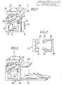
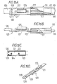
- the cover strip (11) is an extruded translucent/transparent plastics element, for example a polycarbonate material, which is designed to form an insert into the upper end of the channel-section base strip (12) to provide a waterproof covering therefor which can be readily snapped into the base strip and, when required, can be readily levered out of the base section to provide access to the interior lighting compartment (17) defined within the lower portion of the base strip (10).
- the cover (11) has a pair of downwardly projecting side walls (18,19) which resiliently engage the upper portions of the side walls (13,14) of the base strip (10).
- the cover strip (12) also has a pair of elongate downward projections (20,21) which diverge from one another in the downward direction. The free edges of these projections (20,21) are rounded in a semi-circular shape.
- the projections (15,16) of the base strip and the projections (20,21) of the cover strip are dimensioned to provide snap connection means between the cover strip (11) and the base strip (10) when the cover strip is pressed downwardly onto the base strip.
- all these projections are deformed to allow the projections (20,21) to pass between the projections (15,16) and to provide a resilient connecting means therebetween when the cover strip (11) is fully inserted into the mouth of the channel-section base strip (10).
- Figure 2 shows a construction generally similar to that illustrated in Figure 1.
- the base member (30) is formed as an aluminium or similar extrusion having a pair of upwardly extending connecting projections (31,32) with a similar form to the projections (15,16) of the embodiment of Figure 2,
- the cover strip (11) is an extruded polycarbonate member as utilized in the Figure 2 embodiment which fits on top of the base strip (30) with its elongate projections (20,21) forming a snap connection with the relatively rigid projections (31,32) of the base strip.
- a lining (33) of electrically insulating material is provided within the channel-section of the base strip (30) to prevent short circuiting of a lighting unit disposed in use in the base strip (30) of any other means of insulating electrical circuits.
- Figure 4 illustrates a construction generally similar to that shown in Figure 3 with the addition of a sloping flange (45) which is integral with the upper end of the left-hand side wall (44) of the base strip (40) to extend downwardly therefrom to engage an adjoining uncarpeted floor area (46).
- This construction could therefore be used for placing an illuminated strip between a carpeted floor area and an adjoining wooden, concrete or lino floor area.
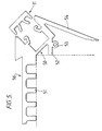
- Figure 5 shows a further construction of a channel-section base strip and cooperating covering strip which is incorporated in a stair nosing device.
- the general form of the base strip (50) is similar to that shown in Figure 1 and a similar insert member (11) is used therewith.
- the base strip (50) is formed integral with and oblique to a stair tread engaging portion (51) formed at its upper surface with a rebate (56) for receiving a non-slip insert.
- the base strip (50) is therefore set at the upper edge of the riser portion of the stair to provide an illuminated nosing therefor.
- the base channel-strip (50) is formed with an obliquely extending leg portion (52) for engaging against the stair riser and leg portion (52) is formed at its ends with eyelets (53) for receiving screws for fixing end caps for covering the opposite open ends of the base strip (50) and cover strip (11) combination.
- the base strip (50) is also formed with an integral side plate (54) which extends from the upper end of its right-hand side wall downwardly and inwardly towards the stair riser. The free edge of the plate (54) is formed with a gripping portion to engage carpeting or other floor covering lying over the stair riser.
- the tubular housing may be in the form of a one-piece elongate member having an axial internal cavity to receive a lighting system according to the invention.
- the member may be, for example, square, circular, oval or polygonal in shape. It may be made, for example, of glass, polycarbonate, acrylic or polyvinylchloride, so that it can be either rigid or flexible in construction.
- the tube may be ribbed along its external surface to provide a reinforced construction. Such a construction may have many possible applications, for example, for providing a neat, attractive and unobtrusive illumination for paintings or other works of art, or for alternatives to night-lights.
- a lighting system comprises elongate electric lighting circuitry which may be received within the lighting chamber or internal cavity of a tubular housing, e.g. of the types described above.
- the lighting circuitry may however be located in a wide range of different types of containers to suit a wide variety of possible usages; indeed the circuitry could be located, for example, between two sheets of glass or the circuitry could be surface mounted and used without any housing at all.
- a lighting system comprises a set of elongate circuit strips each of a finite, predetermined length, which are adapted for the connection thereto of lighting elements which may be in the form, for example, of incandescent indicators, light emitting diodes, or other suitable light emitting sources which are spaced along the system, when assembled, at predetermined spaced intervals, generally, but not necessarily, regularly spaced intervals.
- the elongate strips could be in the form of ribbon cable having the circuit wiring provided therein, the ribbon cable being pierced with a punching tool at given positions to receive fittings for locating the illuminating members and other ancilliary electrical circuit elements.
- the elongate strips are provided by circuit boards, which are preferably semi-rigid so that they have a certain amount of flexibility, of predetermined lengths on which the electric circuitry is provided.
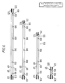
- lighting systems according to the invention comprise a set of a number of different length, flexible circuit boards on each of which the electric circuitry is arranged to provide a series connection between the lamp elements, as illustrated in Fig. 6.
- Each circuit board has two voltage supply lines (67,68) and an electric line (69) connected in parallel across the voltage supply lines (67,68), which connects in series the lamps associates with that board and any compensating resistor.
- the system illustrated in Fig. 6 comprises four different, finite lengths of circuit board, having circuitry for mounting six, five, four and one lamp, respectively, at regularly spaced positions (100).
- an appropriate resistor is generally mounted at a position (101) in order to make all the circuit boards in the set voltage compatible with one another.
- lamps (60) of the same voltage rating are used throughout, although this is not essential.
- appropriate resistors (66) are used to make all the circuit boards in the set voltage compatible with each other and with the desired supply voltage.
- different sets of standard circuit boards can be provided having different spacings between the location positions of the lamps for any linear length of illumination constructed by coupling the appropriate number and size of circuit boards end to end using coupling elements described below. Examples of such spacings are 50 mm, 75 mm and 100 mm. However in other constructions irregular spacings may be selected for special effects.
- Each coupling element (110) comprises an outer housing (111) comprising an upper part (112) and a lower part (113) snap fitted together.
- Each housing part (112,113) comprises an oblong tray-like member having upstanding peripheral wall portions with resilient pegs (114) provided on abutting edges of the wall portions of the two housing parts (112,113) to engage in corresponding apertures in the opposite abutting edges to provide a snap connection means for the two housing parts, which are disposed in inverted positions with respect to one another.
- the end walls of the housing parts (112,113) are recessed to provide an entry slot (115) for receiving end portions of two circuit boards to be joined end to end by the coupling element (110).
- Three location formations (118) of oblong cross-section are integrally formed between the dividing walls (116) and the longitudinal side walls of the parts (112,113) for engagement in centrally located recesses (119) in the connecting elements (117).
- Each connecting element (117) has, at each end, a pair of resilient forks (120) for making electrical connections with the circuitry provided on the circuit boards (65).
- a voltage supply connector element (120) is provided for coupling to one end of a linear series of circuit boards (65) joined together by coupling elements (110).
- the connector element (120) includes a terminal portion (121) provided by a short strip of circuit board having a circuit track arrangement, as illustrated in Fig. 16C, provided thereon.
- the circuit track comprises a negative electric line (122) and a positive electric line (123) which has connector points (124) for connection therein, e.g. by soldering, of a fuse (125).
- a supply cable (126) has positive and negative feed wires (127,128) which are connected by soldering to positive and negative terminal connector points (129,130) on the circuit board (121).
- the free end portion of the circuit board (121) is inserted into a slot (115) of a coupling element (110) located at the end of a circuit board (65) disposed at one end of the linear series thereof.
- the outer pair of electrical connecting elements (117) of the coupling element make electrical contact with the positive and negative lines (123,122), on the circuit board (121) to connect the supply voltage across the voltage supply lines (67,68) on the circuit board (65), to provide the voltage supply of the lighting system.
- a flexible connecting device (130) for allowing the connection of adjacent circuit boards in a series thereof, which boards may be set at different angular positions relative to one another.
- the device (130) comprises a pair of similar connector portions (131) made of a short strip of circuit board having a circuit provided thereon, as illustrated in Fig. 17C, consisting of three electric lines, i.e. positive line (132), a negative line (133) and a central line (134).
- the connector portions (131) are joined by flexible jumper wires (136,137,138) which electrically connect the positive lines (132), the negative lines (133) and the central lines (134) on the connector portions (131).
- Circuit board (65) can be cut to fit around each corner with the cut pieces then being coupled together using flexible connector devices (130). Firstly, coupling devices(110)are engaged with the cut ends of the circuit board (65). Then, the connecting portions (131) of a connector device (130) are engaged in the open slots (115) of the respective coupling devices (110).
- the flexible jumper wires allow the cut sections of the circuit boards (65) to be located along different sides of the aforesaid structure.
- the voltage supply lines (67,68) of the two parts of the severed circuit board (65) are connected by the jumper wires (136,137) and the series connection lines (69) are connected by the jumper wire (138).
- circuit boards (65) which fit precisely the lengths along each side of the rectangular structure without any need for cutting any of the circuit boards (65).
- the same coupling devices (110) and flexible connector devices (130) are utilized at the corners, but in this arrangement the central jumper wire (138) is redundant in operation.
- voltage supply connectors may be connected to both ends of the electrically coupled series of circuit boards (65) to maintain the voltage along the entire length of the system.
- a set of calculation charts are preferably provided for each set of circuit boards for operation at a predetermined supply voltage and using illuminating devices of a predetermined operating voltage.
- the charts give a concordance between the number of lamps required, at the preselected spacing therebetween, for any length as measured on site.
- a further concordance chart then gives the required number of circuit boards of the different lengths in the set for that length in dependence on the number of lamps required.
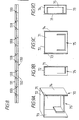
- FIG 8 illustrates an alternative electrical circuitry for the circuit board elements (130) of a lighting system according to the invention.
- each lamp is connected in parallel across the voltage supply lines (131,132) at regularly spaced positions (133), providing an entirely "parallel" circuit arrangement of the lamps.
- a single standard length of circuit board would normally be provided together with connector elements (110), because an end circuit board can be cut between any two adjacent lamp positions to fit the required length of the system. This is not, of course, possible with a "series parallel" arrangement.
- the "series parallel” arrangement will generally be the preferred construction for a lighting system according to the invention because the lamps required are of lower rated voltages so that a greatly reduced current flow, e.g. one quarter the current of a parallel arrangement, is present in operation of the system. This provides a safer system which is generally more compact because lower rated, and therefore smaller components are needed. Moreover the voltage drop along the length of a "series parallel” arrangement is less than with an entirely “parallel” arrangement so that longer linear lengths can be achieved with a “series parallel” system.
- a specific example of a practical system according to the invention is designed to operate at 24V (AC or DC) with lamps of 5V for a "series parallel” arrangement, and a maximum current flow of 3 amps.
- a flashing system can be produced using an entirely "parallel" arrangement having zena diodes associated with each lamp and a switching circuit associated with the voltage supply to switch the polarity of the voltage supply lines.
- This arrangement could employ three voltage supply lines, two separate positive lines and one neutral line with alternate pairs of lamps plus controlling zena diodes being connected between the neutral line and a respective positive voltage supply line which together with a corresponding switching circuit produces a linear flowing effect by lighting in sequence the lamps in each group of four thereof along the length of the lighting system.
- all three of the electric connectors (117) of the intermediate coupling elements (110) is employed to make electrical connections between the neutral and the two positive supply lines on adjacent circuit boards.
- a lighting system according to the invention would normally be supplied as a kit comprising standard finite length of flexible circuit boards and coupling elements allowing any required linear length to be built up from these components.
- the positioning of the lamps on the circuit boards, and the length of the coupling elements is such that, when a set of such boards are coupled in a linear series, the required predetermined spacing of the lamps along the entire length of the coupled boards is achieved.
- further boards may be provided for an end of any coupled series to accommodate a voltage supply connecting element whilst still maintaining the required predetermined spacing relationship between the lamps along the entire length of any coupled series of circuit boards.
- Each strip (65) may be, for example 50 cm long, 5 mm wide and 1 mm thick. Ten or twenty strips and copper tracking thereof can be formed side by side on a single substrate. A router may separate the individual strips leaving connecting pips therebetween. Alternatively no routing may be carried; instead the strips may be separated at a later stage by a multi-saw device. The lamps and resistors are then inserted on the upper sides of the strips with the terminal portions pushed through the strips to engage solder pads on the copper tracking formed on the underside of the strips. The terminals are cropped and soldered to those pads. The boards are then introduced into a defluxing bath when they are degreased and defluxed. They are blasted with lacquer or other insulating sealant in order to protect the copper tracking from oxidization. After the lacquer has dried the individual circuit boards are snapped apart and finished to remove the connecting pips or are separated by a multi-saw device.
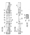
- Figure 18 illustrates another possible embodiment comprising a channel-section, extruded base housing (200) having electric voltage supply tracks (201 and 202) located within corresponding rebates (203 and 204) formed in the opposite side walls of the housing (200).
- the base of the housing is formed with a part-circular recess (205) extending along its length.
- the base housing extrusion is cut to a length in accordance with the required application and secured to the support surface by screws or adhesive.
- the modules described above are, in this embodiment, in the form of circuit boards (206) which is encapsulated in an elongate cast or moulded section (207).
- the lamps (208) and their associated electric circuitry are provided on the circuit board (206) before encapsulation.
- Resilient contact members(209,210) associated with the circuitry on the board (206) protrude outwardly of opposite sides of the module (207) to make contact with the voltage supply tracks (201,202), when the module is located in the housing (200), to apply a voltage across the lamps (208).
- a part-circular beading (211) is provided along the underside of each module (207) to plug into the recess (205) in the base of the housing (200).
- the required lighting system is built up from a selected group of modules (207), equivalent to the above described set of circuit boards of the previous embodiments, to provide lamps at the required spaced locations along the housing (200), after it has been cut to length and secured to the respective support surface.
- the modules are then plugged into the housing (200) with the required electrical connections being made automatically by engagement of the contact member (209,210) with the voltage supply tracks (201,202) in the housing.
- a voltage supply is then connected to the end of the housing (200) to apply the required running voltage of the system across the tracks (201,202).
- a pair of such lines may be provided in one side wall of the housing (200).
- a further resilient contact is then provided in association with each module (207) and the two such contacts at the same side of the module, are disposed at positions staggered along the module.
Landscapes
- Engineering & Computer Science (AREA)
- Architecture (AREA)
- Civil Engineering (AREA)
- Structural Engineering (AREA)
- General Engineering & Computer Science (AREA)
- Arrangement Of Elements, Cooling, Sealing, Or The Like Of Lighting Devices (AREA)
- Non-Portable Lighting Devices Or Systems Thereof (AREA)
- Circuit Arrangement For Electric Light Sources In General (AREA)
Applications Claiming Priority (2)
| Application Number | Priority Date | Filing Date | Title |
|---|---|---|---|
| GB888807758A GB8807758D0 (en) | 1988-03-31 | 1988-03-31 | Decorative lighting system |
| GB8807758 | 1988-03-31 |
Publications (3)
| Publication Number | Publication Date |
|---|---|
| EP0336601A2 true EP0336601A2 (de) | 1989-10-11 |
| EP0336601A3 EP0336601A3 (en) | 1990-05-30 |
| EP0336601B1 EP0336601B1 (de) | 1994-05-11 |
Family
ID=10634474
Family Applications (1)
| Application Number | Title | Priority Date | Filing Date |
|---|---|---|---|
| EP89302805A Expired - Lifetime EP0336601B1 (de) | 1988-03-31 | 1989-03-21 | Dekorative Beleuchtungsvorrichtung |
Country Status (6)
| Country | Link |
|---|---|
| US (2) | US4994944A (de) |
| EP (1) | EP0336601B1 (de) |
| CA (1) | CA1306731C (de) |
| DE (1) | DE68915200T2 (de) |
| ES (1) | ES2052905T3 (de) |
| GB (1) | GB8807758D0 (de) |
Cited By (8)
| Publication number | Priority date | Publication date | Assignee | Title |
|---|---|---|---|---|
| WO1992014092A1 (en) * | 1991-02-06 | 1992-08-20 | Existalite Limited | Lighting system |
| US5412544A (en) * | 1991-08-30 | 1995-05-02 | Loctite Luminescent Systems, Inc. | Method of illuminating and providing emergency egress guidance for hazardous areas |
| WO1999006759A1 (en) | 1997-07-28 | 1999-02-11 | Hewlett-Packard Company | Strip lighting |
| WO2004102069A1 (en) * | 2003-05-19 | 2004-11-25 | Andrzej Szymanski | Fitting of a linear light source |
| EP1233232A3 (de) * | 2001-02-15 | 2005-01-19 | HAPPICH Fahrzeug- und Industrieteile GmbH | Beleuchtungseinrichtung |
| EP2851487A1 (de) * | 2013-09-13 | 2015-03-25 | DURAL GmbH | Montagesystem, insbesondere zur Montage an einer mit einer mineralischen Flächenbekleidung versehenen Wand |
| EP2754776A3 (de) * | 2013-01-11 | 2015-07-08 | Schlüter-Systems KG | Profilsystem zur Begrenzung einer Plattenbekleidung |
| IT202000030860A1 (it) * | 2020-12-15 | 2022-06-15 | Achamar Sagl | Dispositivo e sistema di illuminazione |
Families Citing this family (85)
| Publication number | Priority date | Publication date | Assignee | Title |
|---|---|---|---|---|
| US5321593A (en) * | 1992-10-27 | 1994-06-14 | Moates Martin G | Strip lighting system using light emitting diodes |
| US5337225A (en) * | 1993-01-06 | 1994-08-09 | The Standard Products Company | Lighting strip system |
| US5563472A (en) * | 1994-12-14 | 1996-10-08 | Luminescent Systems, Inc. | Integrated fuse lighting system |
| AU4602196A (en) * | 1994-12-14 | 1996-07-03 | Luminescent Systems, Inc. | Led light strip with brightness/current draw control circuitry |
| US5541823A (en) * | 1995-02-16 | 1996-07-30 | Fallon Luminous Products Corp. | Housing assembly for illuminated glass tubing |
| US5583394A (en) * | 1995-05-23 | 1996-12-10 | Astronics Corporation, Inc. | Electroluminescent lamp with registration index feature and method of making the same |
| US5927845A (en) | 1995-08-28 | 1999-07-27 | Stantech | Integrally formed linear light strip with light emitting diodes |
| US5848837A (en) * | 1995-08-28 | 1998-12-15 | Stantech | Integrally formed linear light strip with light emitting diodes |
| DE19627856A1 (de) * | 1996-07-11 | 1998-01-15 | Happich Fahrzeug & Ind Teile | Beleuchtungsleiste und Verfahren zur Herstellung |
| US6582103B1 (en) | 1996-12-12 | 2003-06-24 | Teledyne Lighting And Display Products, Inc. | Lighting apparatus |
| US6720745B2 (en) * | 1997-08-26 | 2004-04-13 | Color Kinetics, Incorporated | Data delivery track |
| US6806659B1 (en) * | 1997-08-26 | 2004-10-19 | Color Kinetics, Incorporated | Multicolored LED lighting method and apparatus |
| US6113248A (en) | 1997-10-20 | 2000-09-05 | The Standard Products Company | Automated system for manufacturing an LED light strip having an integrally formed connector |
| US5934793A (en) * | 1997-12-10 | 1999-08-10 | Minami International Corp. | Net lights |
| US7132804B2 (en) * | 1997-12-17 | 2006-11-07 | Color Kinetics Incorporated | Data delivery track |
| ES1040474Y (es) * | 1998-05-21 | 1999-08-16 | Ibero Alcorense S L | Pieza para formacion de cenefas de revestimiento con luz. |
| US6183107B1 (en) * | 1998-09-22 | 2001-02-06 | Genlyte Thomas Group Llc | Multi-lamp assembly for miniature lighting strips |
| US6585393B1 (en) * | 1998-10-09 | 2003-07-01 | Satco Products, Inc. | Modular accent light fixture |
| FR2794217B1 (fr) * | 1999-05-28 | 2001-07-20 | Schneider Electric Ind Sa | Element de colonne lumineuse |
| US6796680B1 (en) * | 2000-01-28 | 2004-09-28 | Lumileds Lighting U.S., Llc | Strip lighting |
| US6406166B1 (en) * | 2000-05-30 | 2002-06-18 | Yu-Chow Ko | Chasing rope light |
| US7202613B2 (en) * | 2001-05-30 | 2007-04-10 | Color Kinetics Incorporated | Controlled lighting methods and apparatus |
| US6676275B2 (en) | 2001-04-13 | 2004-01-13 | Farsight Llc | Portable, adaptable set lighting system |
| US7063440B2 (en) * | 2002-06-03 | 2006-06-20 | Everbrite, Llc | LED accent lighting units |
| US7300192B2 (en) * | 2002-10-03 | 2007-11-27 | Color Kinetics Incorporated | Methods and apparatus for illuminating environments |
| US6945669B1 (en) | 2003-04-14 | 2005-09-20 | Jester Randy D | Film encapsulated strand of lights |
| US7066619B2 (en) * | 2003-08-29 | 2006-06-27 | Waters Michael A | LED picture light apparatus and method |
| US7033044B2 (en) | 2003-10-16 | 2006-04-25 | Farsight Llc | Horizontally and vertically adjustable lighting system and method |
| US20050239544A1 (en) * | 2004-04-27 | 2005-10-27 | Steelman Paul C | Self-contained integrated audio, lighting and surveillance system |
| US8188503B2 (en) | 2004-05-10 | 2012-05-29 | Permlight Products, Inc. | Cuttable illuminated panel |
| US20060044796A1 (en) * | 2004-08-24 | 2006-03-02 | Harvatek Corporation | Mixing light board |
| CN101065316B (zh) * | 2004-11-26 | 2014-01-29 | 奥蒂斯电梯公司 | 载人运送器玻璃栏杆发光 |
| JP4241658B2 (ja) * | 2005-04-14 | 2009-03-18 | シチズン電子株式会社 | 発光ダイオード光源ユニット及びそれを用いて形成した発光ダイオード光源 |
| US7918591B2 (en) | 2005-05-13 | 2011-04-05 | Permlight Products, Inc. | LED-based luminaire |
| EP1760392A1 (de) * | 2005-08-29 | 2007-03-07 | Patent-Treuhand-Gesellschaft für elektrische Glühlampen mbH | Montagestruktur für Beleuchtungsanordnung mit Leuchtdioden |
| CA2578720C (en) * | 2006-02-14 | 2012-10-23 | Acuity Brands, Inc. | Illuminated sign insert |
| US7845103B2 (en) | 2006-02-14 | 2010-12-07 | Acuity Brands, Inc. | Illuminated sign mounting structure |
| US20080094832A1 (en) * | 2006-10-18 | 2008-04-24 | Altamura Steven J | Decorative light display |
| DE102007001533A1 (de) * | 2007-01-10 | 2008-07-17 | Osram Opto Semiconductors Gmbh | Leuchtdiodensystem |
| US8960935B2 (en) * | 2007-01-31 | 2015-02-24 | Lg Display Co., Ltd. | Backlight unit and liquid crystal display device having the same |
| US7815341B2 (en) * | 2007-02-14 | 2010-10-19 | Permlight Products, Inc. | Strip illumination device |
| US20090200966A1 (en) * | 2007-05-16 | 2009-08-13 | Amdor, Inc. | Illumination unit with current interrupter component |
| CN101680624B (zh) * | 2007-07-27 | 2012-09-26 | 夏普株式会社 | 照明装置和使用它的显示装置 |
| US7854616B2 (en) | 2007-10-12 | 2010-12-21 | The L.D. Kichler Co. | Positionable lighting systems and methods |
| WO2009066215A1 (en) * | 2007-11-23 | 2009-05-28 | Koninklijke Philips Electronics N.V. | Tufted textile |
| US8388184B2 (en) * | 2007-11-23 | 2013-03-05 | Koninklijke Philips Electronics N.V. | Light emitting tufted carpet |
| DE102007057765A1 (de) * | 2007-11-30 | 2009-06-04 | Osram Gesellschaft mit beschränkter Haftung | LED-System, LED-Leuchte und Verfahren zum Zusammenbau eines LED-Systems |
| US7549784B1 (en) * | 2007-12-06 | 2009-06-23 | New Horizon Designs, Inc. | LED lighting for glass tiles |
| US20110255287A1 (en) * | 2008-07-08 | 2011-10-20 | Li Qing Charles | Connectors for led strip lighting |
| US9228732B2 (en) | 2008-07-08 | 2016-01-05 | Us Vaopto, Inc. | Modular LED lighting systems, including flexible, rigid, and waterproof lighting strips and connectors |
| US8641229B2 (en) | 2008-07-08 | 2014-02-04 | Virginia Optoelectronics, Inc. | Waterproof flexible and rigid LED lighting systems and devices |
| USD650114S1 (en) * | 2008-07-18 | 2011-12-06 | 3M Innovative Properties Company | Lighting device |
| DE102008034956A1 (de) * | 2008-07-25 | 2010-02-04 | Signal-Construct Gmbh | Verbindungselement zur Bildung bandförmiger Beleuchtungen und damit hergestelltes Beleuchtungselement |
| US7819553B2 (en) * | 2008-08-14 | 2010-10-26 | Lexso John C | Modular light strand kit |
| JP4465399B2 (ja) * | 2008-09-16 | 2010-05-19 | シャープ株式会社 | 照明灯 |
| DE102008056923A1 (de) * | 2008-11-12 | 2010-05-27 | Osram Gesellschaft mit beschränkter Haftung | Beleuchtungsvorrichtung mit zwei Leiterplatten |
| US8251543B2 (en) * | 2008-11-22 | 2012-08-28 | Innovative Lighting, Inc. | Interior corner mounting module for rope light system |
| TW201020360A (en) * | 2008-11-26 | 2010-06-01 | Shienq Huong Entpr Co Ltd | Light-emitting ribbon |
| US20100226139A1 (en) * | 2008-12-05 | 2010-09-09 | Permlight Products, Inc. | Led-based light engine |
| US8297788B2 (en) * | 2008-12-08 | 2012-10-30 | Avx Corporation | Card edge LED strip connector and LED assembly |
| DE102009019285A1 (de) | 2009-04-30 | 2010-11-04 | Osram Gesellschaft mit beschränkter Haftung | Beleuchtungssystem mit mindestens einem Leuchtband |
| DE102009055859A1 (de) * | 2009-11-26 | 2011-06-01 | Osram Gesellschaft mit beschränkter Haftung | Verfahren zum Kontaktieren einer beidseitig mit elektrischen Kontakten versehenen Leiterplatte und solche Leiterplatte |
| US9563008B2 (en) * | 2010-09-17 | 2017-02-07 | Lg Innotek Co., Ltd. | Lighting module and lighting apparatus including the same |
| DE102010062185A1 (de) * | 2010-11-30 | 2012-05-31 | Osram Ag | Leuchtmittelhalterung, Anschlussstück und System mit Leuchtmittelhalterung und Anschlussstück |
| DE102011017702A1 (de) * | 2011-04-28 | 2012-10-31 | Zumtobel Lighting Gmbh | Lichtbandsystem und Konvertereinheit hierfür |
| US8616905B2 (en) | 2011-08-18 | 2013-12-31 | Lowe's Companies, Inc. | Connector having a top cap to create an electrical connection between an electrical cable and an electrical contact |
| TWI443281B (zh) * | 2011-10-21 | 2014-07-01 | Lextar Electronics Corp | 燈條結構 |
| US20130099685A1 (en) * | 2011-10-21 | 2013-04-25 | Gemmy Industries Incorporated | Flexible Tubular Lighting System |
| US9565769B2 (en) | 2014-02-19 | 2017-02-07 | Elemental LED, Inc. | LED linear lighting kit |
| US9279544B1 (en) | 2014-02-19 | 2016-03-08 | Elemental LED, Inc. | LED linear lighting strip |
| US9551161B2 (en) * | 2014-11-30 | 2017-01-24 | Dolby Laboratories Licensing Corporation | Theater entrance |
| US10145552B2 (en) * | 2015-03-26 | 2018-12-04 | Lux Lighting Systems, Llc | Magnetic light emitting diode (LED) lighting system |
| USD775374S1 (en) | 2015-08-07 | 2016-12-27 | Peak Innovations Inc. | Railing |
| USD802799S1 (en) | 2015-08-07 | 2017-11-14 | Peak Innovations Inc. | Cap for a railing |
| USD802398S1 (en) | 2015-08-07 | 2017-11-14 | Peak Innovations Inc. | Bracket |
| US9874324B2 (en) | 2015-09-29 | 2018-01-23 | Steven E. Attard | Screened enclosure lighting system |
| US9874323B1 (en) * | 2015-09-29 | 2018-01-23 | Steven E. Attard | Screened enclosure lighting system |
| CN113090968B (zh) * | 2015-10-26 | 2023-06-23 | J·P·霍夫曼 | Led灯线性带、安装结构和夹子组件 |
| US9976711B2 (en) * | 2016-08-17 | 2018-05-22 | Michael Simmons | Speed tape assembly for LED strip tapes in light box |
| JP2019011575A (ja) * | 2017-06-29 | 2019-01-24 | ハンディテクノ株式会社 | デッキ用端先材 |
| CN109668073A (zh) * | 2017-10-16 | 2019-04-23 | 华夏晶锐照明科技(北京)股份有限公司 | 台阶灯 |
| CN107967890B (zh) * | 2017-11-08 | 2020-08-11 | 深圳市屯奇尔科技有限公司 | 直径错位采样旋转rgb灯带显示方法、装置及计算机可读存储介质 |
| EP3935310A1 (de) * | 2019-03-06 | 2022-01-12 | Lumileds Holding B.V. | Modulare led-kette |
| CN115812341A (zh) | 2020-07-09 | 2023-03-17 | 昕诺飞控股有限公司 | 照明带 |
| US11835190B1 (en) | 2023-09-01 | 2023-12-05 | Logo Design Group, Llc | Size adjustable light emitting diode light system with three light projection planes |
Family Cites Families (7)
| Publication number | Priority date | Publication date | Assignee | Title |
|---|---|---|---|---|
| US3755663A (en) * | 1971-11-17 | 1973-08-28 | Shelly Ass Inc | Electrical display device and method of making the same |
| SE390335B (sv) * | 1975-04-14 | 1976-12-13 | Belysning Ab Aneta | Belysningsanordning |
| US4096379A (en) * | 1976-08-24 | 1978-06-20 | Albert Taylor | Modular illumination device |
| US4413311A (en) * | 1981-09-01 | 1983-11-01 | Philip Orenstein | Connection system for joining illuminated modules |
| US4607317A (en) * | 1984-08-14 | 1986-08-19 | Lin Ta Yeh | Non-neon light |
| US4654765A (en) * | 1985-09-23 | 1987-03-31 | Laidman Jerry H | Low voltage lighting system replaceable bulb assembly |
| GB8807387D0 (en) * | 1988-03-29 | 1988-05-05 | Lightgraphix Ltd | Improvements relating to lighting apparatus |
-
1988
- 1988-03-31 GB GB888807758A patent/GB8807758D0/en active Pending
-
1989
- 1989-03-21 DE DE68915200T patent/DE68915200T2/de not_active Expired - Lifetime
- 1989-03-21 ES ES89302805T patent/ES2052905T3/es not_active Expired - Lifetime
- 1989-03-21 EP EP89302805A patent/EP0336601B1/de not_active Expired - Lifetime
- 1989-03-24 US US07/328,455 patent/US4994944A/en not_active Expired - Lifetime
- 1989-03-29 CA CA000595466A patent/CA1306731C/en not_active Expired - Lifetime
-
1991
- 1991-02-12 US US07/654,193 patent/US5107408A/en not_active Expired - Lifetime
Cited By (11)
| Publication number | Priority date | Publication date | Assignee | Title |
|---|---|---|---|---|
| WO1992014092A1 (en) * | 1991-02-06 | 1992-08-20 | Existalite Limited | Lighting system |
| AU656168B2 (en) * | 1991-02-06 | 1995-01-27 | Existalite Limited | Lighting system |
| US5412544A (en) * | 1991-08-30 | 1995-05-02 | Loctite Luminescent Systems, Inc. | Method of illuminating and providing emergency egress guidance for hazardous areas |
| WO1999006759A1 (en) | 1997-07-28 | 1999-02-11 | Hewlett-Packard Company | Strip lighting |
| EP1000295A4 (de) * | 1997-07-28 | 2008-03-19 | Lumileds Lighting Llc | Lichtleiste |
| EP2796781A3 (de) * | 1997-07-28 | 2015-05-27 | Philips Lumileds Lighting Company, LLC. | Streifenbeleuchtung |
| EP1233232A3 (de) * | 2001-02-15 | 2005-01-19 | HAPPICH Fahrzeug- und Industrieteile GmbH | Beleuchtungseinrichtung |
| WO2004102069A1 (en) * | 2003-05-19 | 2004-11-25 | Andrzej Szymanski | Fitting of a linear light source |
| EP2754776A3 (de) * | 2013-01-11 | 2015-07-08 | Schlüter-Systems KG | Profilsystem zur Begrenzung einer Plattenbekleidung |
| EP2851487A1 (de) * | 2013-09-13 | 2015-03-25 | DURAL GmbH | Montagesystem, insbesondere zur Montage an einer mit einer mineralischen Flächenbekleidung versehenen Wand |
| IT202000030860A1 (it) * | 2020-12-15 | 2022-06-15 | Achamar Sagl | Dispositivo e sistema di illuminazione |
Also Published As
| Publication number | Publication date |
|---|---|
| EP0336601A3 (en) | 1990-05-30 |
| US5107408A (en) | 1992-04-21 |
| CA1306731C (en) | 1992-08-25 |
| US4994944A (en) | 1991-02-19 |
| EP0336601B1 (de) | 1994-05-11 |
| DE68915200D1 (de) | 1994-06-16 |
| DE68915200T2 (de) | 1994-12-08 |
| ES2052905T3 (es) | 1994-07-16 |
| GB8807758D0 (en) | 1988-05-05 |
Similar Documents
| Publication | Publication Date | Title |
|---|---|---|
| US4994944A (en) | Decorative lighting system | |
| US4628421A (en) | Strip lighting | |
| US6914194B2 (en) | Flexible LED cable light | |
| US9836999B2 (en) | LED backlight system for cabinet sign | |
| US4908743A (en) | Strip lighting assembly | |
| US4173035A (en) | Tape strip for effecting moving light display | |
| US3527933A (en) | Flat electrical connecting element | |
| CN101536066B (zh) | 用于箱体标牌的led背光系统 | |
| CA2671360A1 (en) | Modular led lighting systems and flexible or rigid strip lighting devices | |
| US20190049077A1 (en) | Flexible Power Distribution System | |
| EP0570441B1 (de) | Beleuchtungssystem | |
| EP3321561A1 (de) | Steckerleiste für modulares beleuchtungssystem | |
| US10174923B2 (en) | Hanger for a modular lighting system having a main body with two channels to accommodate two segments of a power bar | |
| US10041662B2 (en) | Light bar for a lighting system | |
| US20050157495A1 (en) | Conductor rail system for low-voltage luminairies and light-emitting diodes | |
| US6019486A (en) | Lighting device | |
| EP3321568A1 (de) | Seitlich gestützte leuchten | |
| US6717360B2 (en) | Flexible electroluminescent strip having supplementary control conductor | |
| DE4134836A1 (de) | Leuchte | |
| KR960006351Y1 (ko) | 진열용 조명장치 | |
| HK1082024A (en) | Modular lighting system including high-powered led lighting modules | |
| JP2003195793A (ja) | 照明装置 |
Legal Events
| Date | Code | Title | Description |
|---|---|---|---|
| PUAI | Public reference made under article 153(3) epc to a published international application that has entered the european phase |
Free format text: ORIGINAL CODE: 0009012 |
|
| AK | Designated contracting states |
Kind code of ref document: A2 Designated state(s): BE DE ES FR GB IT NL SE |
|
| PUAL | Search report despatched |
Free format text: ORIGINAL CODE: 0009013 |
|
| AK | Designated contracting states |
Kind code of ref document: A3 Designated state(s): BE DE ES FR GB IT NL SE |
|
| 17P | Request for examination filed |
Effective date: 19901115 |
|
| 17Q | First examination report despatched |
Effective date: 19930218 |
|
| RAP1 | Party data changed (applicant data changed or rights of an application transferred) |
Owner name: EXISTALITE LIMITED |
|
| GRAA | (expected) grant |
Free format text: ORIGINAL CODE: 0009210 |
|
| AK | Designated contracting states |
Kind code of ref document: B1 Designated state(s): BE DE ES FR GB IT NL SE |
|
| REF | Corresponds to: |
Ref document number: 68915200 Country of ref document: DE Date of ref document: 19940616 |
|
| REG | Reference to a national code |
Ref country code: ES Ref legal event code: FG2A Ref document number: 2052905 Country of ref document: ES Kind code of ref document: T3 |
|
| ITF | It: translation for a ep patent filed | ||
| ET | Fr: translation filed | ||
| K2C2 | Correction of patent specification (partial reprint) published |
Effective date: 19940511 |
|
| EAL | Se: european patent in force in sweden |
Ref document number: 89302805.0 |
|
| PLBE | No opposition filed within time limit |
Free format text: ORIGINAL CODE: 0009261 |
|
| STAA | Information on the status of an ep patent application or granted ep patent |
Free format text: STATUS: NO OPPOSITION FILED WITHIN TIME LIMIT |
|
| 26N | No opposition filed | ||
| PGFP | Annual fee paid to national office [announced via postgrant information from national office to epo] |
Ref country code: SE Payment date: 19970319 Year of fee payment: 9 |
|
| PGFP | Annual fee paid to national office [announced via postgrant information from national office to epo] |
Ref country code: ES Payment date: 19970324 Year of fee payment: 9 |
|
| PGFP | Annual fee paid to national office [announced via postgrant information from national office to epo] |
Ref country code: NL Payment date: 19970327 Year of fee payment: 9 |
|
| PGFP | Annual fee paid to national office [announced via postgrant information from national office to epo] |
Ref country code: BE Payment date: 19970521 Year of fee payment: 9 |
|
| PG25 | Lapsed in a contracting state [announced via postgrant information from national office to epo] |
Ref country code: SE Free format text: LAPSE BECAUSE OF NON-PAYMENT OF DUE FEES Effective date: 19980322 |
|
| PG25 | Lapsed in a contracting state [announced via postgrant information from national office to epo] |
Ref country code: ES Free format text: LAPSE BECAUSE OF NON-PAYMENT OF DUE FEES Effective date: 19980323 |
|
| PG25 | Lapsed in a contracting state [announced via postgrant information from national office to epo] |
Ref country code: BE Free format text: LAPSE BECAUSE OF NON-PAYMENT OF DUE FEES Effective date: 19980331 |
|
| BERE | Be: lapsed |
Owner name: EXISTALITE LTD Effective date: 19980331 |
|
| PG25 | Lapsed in a contracting state [announced via postgrant information from national office to epo] |
Ref country code: NL Free format text: LAPSE BECAUSE OF NON-PAYMENT OF DUE FEES Effective date: 19981001 |
|
| NLV4 | Nl: lapsed or anulled due to non-payment of the annual fee |
Effective date: 19981001 |
|
| EUG | Se: european patent has lapsed |
Ref document number: 89302805.0 |
|
| REG | Reference to a national code |
Ref country code: ES Ref legal event code: FD2A Effective date: 20010503 |
|
| REG | Reference to a national code |
Ref country code: GB Ref legal event code: 732E |
|
| REG | Reference to a national code |
Ref country code: FR Ref legal event code: TP |
|
| REG | Reference to a national code |
Ref country code: GB Ref legal event code: IF02 |
|
| PGFP | Annual fee paid to national office [announced via postgrant information from national office to epo] |
Ref country code: GB Payment date: 20080327 Year of fee payment: 20 |
|
| PGFP | Annual fee paid to national office [announced via postgrant information from national office to epo] |
Ref country code: DE Payment date: 20080430 Year of fee payment: 20 Ref country code: FR Payment date: 20080317 Year of fee payment: 20 |
|
| PGFP | Annual fee paid to national office [announced via postgrant information from national office to epo] |
Ref country code: IT Payment date: 20080329 Year of fee payment: 20 |
|
| REG | Reference to a national code |
Ref country code: GB Ref legal event code: PE20 Expiry date: 20090320 |
|
| PG25 | Lapsed in a contracting state [announced via postgrant information from national office to epo] |
Ref country code: GB Free format text: LAPSE BECAUSE OF EXPIRATION OF PROTECTION Effective date: 20090320 |