EP0336566A2 - Mechanismus zum Öffnen und Schliessen der Formen in einer Maschine zum Herstellen von Glasgegenständen - Google Patents
Mechanismus zum Öffnen und Schliessen der Formen in einer Maschine zum Herstellen von Glasgegenständen Download PDFInfo
- Publication number
- EP0336566A2 EP0336566A2 EP19890302320 EP89302320A EP0336566A2 EP 0336566 A2 EP0336566 A2 EP 0336566A2 EP 19890302320 EP19890302320 EP 19890302320 EP 89302320 A EP89302320 A EP 89302320A EP 0336566 A2 EP0336566 A2 EP 0336566A2
- Authority
- EP
- European Patent Office
- Prior art keywords
- chamber
- piston
- mould
- opening
- side portions
- Prior art date
- Legal status (The legal status is an assumption and is not a legal conclusion. Google has not performed a legal analysis and makes no representation as to the accuracy of the status listed.)
- Withdrawn
Links
- 239000012530 fluid Substances 0.000 claims abstract description 11
- 238000007789 sealing Methods 0.000 claims description 11
- 239000006060 molten glass Substances 0.000 claims description 8
- 239000011521 glass Substances 0.000 claims description 4
- 238000000465 moulding Methods 0.000 description 4
- 238000000034 method Methods 0.000 description 3
- 238000013459 approach Methods 0.000 description 2
- 238000007664 blowing Methods 0.000 description 2
- 208000011092 Hand injury Diseases 0.000 description 1
- 230000004075 alteration Effects 0.000 description 1
- 238000010276 construction Methods 0.000 description 1
Images
Classifications
-
- C—CHEMISTRY; METALLURGY
- C03—GLASS; MINERAL OR SLAG WOOL
- C03B—MANUFACTURE, SHAPING, OR SUPPLEMENTARY PROCESSES
- C03B9/00—Blowing glass; Production of hollow glass articles
- C03B9/30—Details of blowing glass; Use of materials for the moulds
- C03B9/34—Glass-blowing moulds not otherwise provided for
- C03B9/353—Mould holders ; Mould opening and closing mechanisms
- C03B9/3532—Mechanisms for holders of half moulds moving by rotation about a common vertical axis
- C03B9/3535—Mechanisms for holders of half moulds moving by rotation about a common vertical axis with the half moulds parallel upon opening and closing
Definitions
- This invention is concerned with an opening and closing mechanism for the moulds of a glassware forming machine.
- the moulds of each section of the machine comprise one or more blank moulds for moulding charges, known as "gobs", of molten glass into parisons, and one or more final moulds for moulding the parisons into completed glass containers.
- These moulds generally comprise two opposed mould side portions which, in the operation of the machine, are moved between mould closed positions thereof, in which the mould side portions engage one another and cooperate in defining a mould cavity in which a gob or parison can be moulded, and mould open positions thereof in which the mould side portions are separated from one another to allow removal of moulded parisons or containers and introduction of further gobs or parisons.
- the mould side portions are moved arcuately about a common axis but, in some machines, the movement is in a straight line.
- a conventional mould opening and closing mechanism comprises a piston and cylinder assembly comprising a cylinder, a piston movable in the cylinder, and a piston rod secured to the piston and operatively connected to the mould side portions.
- the invention provides an opening and closing mechanism operable to move mould side portions of a glassware forming machine between mould closed positions thereof, in which each mould side portion engages another such side portion and cooperates therewith in defining a mould cavity in which molten glass can be moulded, and mould open positions thereof in which the mould side portions are separated from one another to allow removal of moulded glass and introduction of further molten glass, the mechanism comprising a piston and cylinder assembly comprising, a cylinder, a piston moving in the cylinder between a mould open and a mould closed position and comprising a head and a piston rod, a first chamber on one side of the piston head, a second chamber on the other side of the head, the effective area of the piston head bounding the first chamber being greater than that of that bounding the second chamber, characterised in that there are provided passage means in the piston extending from an entrance opening to the first chamber to an exit opening to the second chamber, a check valve in the passage means preventing flow of fluid from the second chamber to the first, a slee
- the full force is not generated until just before the mould side portions reach their mould closed positions so that an operator's hand cannot be subjected to the full force.
- the ratio of the areas of the first and second surfaces of the piston can be arranged so that the closing force can readily be resisted by the operator until the mould side portions reach said positions adjacent to their closed positions which can be arranged so that the gap between the mould side portions is too small to admit the operator's hand.
- the mechanism requires no additional equipment in the vicinity of the mould side portions so that access is not hindered and the mechanism can readily be installed in a conventional machine in place of a conventional mechanism as its cylinder can readily be made in the same external shape as the cylinder of a conventional mechanism.
- the piston rod may extend from said piston throughout the cylinder in both directions, as is conventional, and the portion thereof which extends through said first chamber has a smaller diameter than the portion thereof which extends through said second chamber.
- the effective areas of the first and second surfaces of the piston differ by the difference in cross-sectional areas between the portions of the piston rod.
- the passage means may comprise bores formed in the piston rod and a one-way valve arranged to prevent flow through the bores from the second chamber to the first chamber.
- the bores may have an entrance opening into the first chamber formed by a transverse bore in the piston rod and an exit opening into the second chamber formed by a further transverse bore in the piston rod.
- the passage means may also comprise sealing means, formed by a sealing ring mounted on the piston rod between the exit and the piston arranged to seal said exit when said mould side portions reach said positions adjacent to their mould closed positions by sealingly engaging the wall of a recess in an end cap of the cylinder.
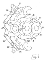
- the illustrative opening and closing mechanism is operable to move mould side portions 10 of two moulds arranged side by side of a glassware forming machine of the individual section type.
- the side portions 10 are moved between mould closed positions thereof (shown in full line in Figure 1) in which each portion 10 engages another such portion and cooperates therewith in defining a mould cavity 12 in which molten glass can be moulded, and mould open positions thereof (shown in broken line in Figure 1) in which the portions 10 are separated from one another to allow removal of moulded glass and introduction of further molten glass.
- the portions 10 are mounted in pairs on supports 14 which are pivotally mounted on pins 16 supported by opposed arms 18 which are mounted in conventional manner on a common pivot pin 20. To move the portions 10 between their mould open and mould closed positions, the arms 18 are pivotally moved about the pin 20 simultaneously one clockwise and the other anti-clockwise.
- the arms 18 have extensions 22 on the opposite side of the pin 20 from the portions 10. These extensions are each pivotally connected to one of two links 24.
- the links 24 are pivotally connected to arms 26 each projecting horizontally from one of two vertical shafts 28 which are mounted in conventional manner to turn about their longitudinal axes.
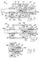
- the shafts 28 are turned about their longitudinal axes, one clockwise and the other anti-clockwise, by the operation of a piston and cylinder assembly 30 of the illustrative mechanism ( Figures 3 and 4)
- the links 24 are moved by the arms 26 and cause the arms 18 to pivot about the pin 20, one clockwise and the other anti-clockwise, thereby moving the portions 10 as aforesaid.
- the piston and cylinder assembly 30 comprises a cylinder 32, having a first end cap 34 and a second end cap 36, a piston 38 movable in the cylinder 32, and a piston rod 40 secured to the piston 38 and operatively connected to the mould side portions 10.
- the piston rod 40 extends throughout the cylinder 32 in both directions from the piston 38 and passes through seals in both end caps 34 and 36.
- the piston rod 40 is pivotally connected to a link (not shown) which is connected to a lever (not shown) mounted to turn about a vertical axis.
- This lever is pivotally connected to two further links (not shown) which are in turn pivotally connected to arms (not shown) which project horizontally from splined sockets (not shown) mounted to turn about horizontal axes and arranged to receive splined lower end portions of the shafts 28.
- These not shown items are of conventional construction and similar to those shown in Figure 8 of the aforementioned U.S. Patent Specification No. 1 911 119.
- the operative connection between the piston rod 40 and the portions 10 is completed by the aforementioned items 26, 24, 18, 16 and 14.
- the piston 38 forms a boundary between a first chamber 42 and a second chamber 44 within the cylinder 32.
- the first chamber 42 is bounded by a first surface 46 of the piston 38, the end cap 34 and the cylinder 32 while the second chamber 44 is bounded a second surface 48 of the piston 38 opposite to the surface 46, the end cap 36 and the cylinder 32.
- the chambers 42 and 44 vary in volume as the piston 38 moves in the cylinder 32.
- Fluid viz. air, under pressure can be introduced into the first chamber 42 through a port 50 in the end cap 34 which divides into two branches, a first branch 50a which passes through a check valve 52 and enters the chamber 42 from the end cap 34, and a second branch 50b which extends into the cylinder 32 before entering the chamber 42.
- the check valve 52 is arranged to prevent air from leaving the cylinder 32 through the branch 50a and comprises a spring-loaded closure member which is displaced against the spring pressure to allow air to enter the cylinder through the branch 50a.
- Introduction of such fluid into the chamber 42 causes the piston 38 to move in a first direction (indicated by the arrow A in Figure 3) to move the mould side portions 10 into their mould closed positions.
- Fluid under pressure can be introduced into the second chamber 44 through a port 55 in the end cap 36 and such introduction causes the piston 38 to move in a second, opposite, direction to move the mould side portions 10 into their mould open positions.
- the end cap 36 also defines a port 54 which divides into a branch 54a, which enters the chamber 44 in a direction parallel to the piston rod 40, and a branch 54b which enters a cylindrical recess 62 in the end cap 36 by passing radially through a bushing 63 which lines the recess 62.
- the port 54 is throttled (not shown) so that air pressure in the chamber 44 is limited.
- the portion 40a of the piston rod 40 which extends through the first chamber 42 has a smaller diameter than the portion 40b thereof which extends through said second chamber 44. Therefore, the first surface 46 of the piston 38 presents a greater effective area on which the fluid under pressure can act than does the second surface 48 of the piston 38.
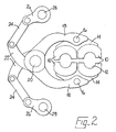
- Passage means 56 are provided which allow fluid to flow from the first chamber 42 to the second chamber 44 during movement of the mould side portions 10 from their mould open positions (shown in broken line in Figure 1) to positions (shown in Figure 2) adjacent to their mould closed positions but prevent such flow during further movement of the mould side portions 10 to their mould closed positions (shown in Figure 1 in full line).
- the passage means 56 comprises a transverse bore 56a through the portion 40a of the piston rod providing entrances at its ends and connecting with a longitudinal bore 56b of the passage means in the piston rod 40.
- the bore 56b contains a one-way valve 58 arranged to prevent flow through the bores from the second chamber 44 into the first chamber 42 and connects with a transverse bore 56c in the portion 40b of the piston rod.
- the bore 56c provides exits at its ends opening into the chamber 44.
- the passage means 56 also comprises sealing means arranged to seal said exits of the bore 56c when said mould side portions 10 reach said positions adjacent to their mould closed positions.
- the sealing means comprises a sealing ring 60 mounted on the portion 40b of the piston rod between said exits and the piston 38.
- the sealing ring 60 is arranged to sealingly engage the internal wall of the bushing 63 in the recess 62 in the end cap 36 of the cylinder 32.
- the recess 62 is cylindrical and coaxial with the piston rod 40.
- a further sealing ring 64 is mounted on the piston rod portion 40b further from the piston 38 than the exits of the bore 56c and is also arranged to sealingly engage the internal wall of the bushing 63.
- the mould side portions 10 are moved away from their mould open positions by introducing air under pressure into the port 50 with the port 54 open and the port 55 closed.
- the air passes through the check valve 52 and enters the first chamber 42.
- the air also enters the bore 56a and flows through the bores 56a, 56b and 56c and the one-way valve 58 into the second chamber 44.
- the surface 46 of the piston 38 has a greater effective area than the surface 48 thereof, the piston 38 moves away from the end cap 34 and the mould side portions 10 move away from their mould open positions.
- the branch 50b of the port 50 is uncovered as the piston 38 moves so that the air flow is increased. During this movement air can escape through the branches 54a and 54b of the port 54 which, as mentioned above, is throttled so that the air pressure in the chamber 44 cannot build up sufficiently to prevent movement of the piston 38.
- the piston 38 moves towards the end cap 36 under low pressure.
- the sealing ring 64 enters the bushing 63, the branch 54b is isolated from the chamber 44 and air can only leave the chamber 44 through the branch 54a so that the end of the motion is cushioned.
- the sealing ring 60 enters the bushing 63 and seals the exits of the bore 56c between the sealing rings 60 and 64. These positions can be arranged so that none of the mould side portions 10 is more than 10 mm from its mould closed position. Once the exits of the bore 56c are sealed the full force is developed on the piston 38 to close the moulds and hold them closed ( Figure 5).
- the port 55 is connected to air under pressure, the port 54 is closed and the port 50 is corrected to exhaust.
Landscapes
- Engineering & Computer Science (AREA)
- Chemical & Material Sciences (AREA)
- Manufacturing & Machinery (AREA)
- Materials Engineering (AREA)
- Organic Chemistry (AREA)
- Moulds For Moulding Plastics Or The Like (AREA)
- Actuator (AREA)
Applications Claiming Priority (2)
| Application Number | Priority Date | Filing Date | Title |
|---|---|---|---|
| GB8807735 | 1988-03-31 | ||
| GB888807735A GB8807735D0 (en) | 1988-03-31 | 1988-03-31 | Opening & closing mechanism for moulds of glassware forming machine |
Publications (1)
| Publication Number | Publication Date |
|---|---|
| EP0336566A2 true EP0336566A2 (de) | 1989-10-11 |
Family
ID=10634459
Family Applications (1)
| Application Number | Title | Priority Date | Filing Date |
|---|---|---|---|
| EP19890302320 Withdrawn EP0336566A2 (de) | 1988-03-31 | 1989-03-08 | Mechanismus zum Öffnen und Schliessen der Formen in einer Maschine zum Herstellen von Glasgegenständen |
Country Status (3)
| Country | Link |
|---|---|
| EP (1) | EP0336566A2 (de) |
| JP (1) | JPH01286929A (de) |
| GB (1) | GB8807735D0 (de) |
Cited By (2)
| Publication number | Priority date | Publication date | Assignee | Title |
|---|---|---|---|---|
| WO2010027856A1 (en) | 2008-08-26 | 2010-03-11 | Owens-Brockway Glass Container Inc. | Apparatus for opening and closing molds in a glassware forming machine |
| IT201700005042A1 (it) * | 2017-01-18 | 2018-07-18 | Bottero Spa | Gruppo attuatore per la movimentazione di un organo operativo, in particolare per una macchina di formatura di articoli di vetro cavi |
Families Citing this family (1)
| Publication number | Priority date | Publication date | Assignee | Title |
|---|---|---|---|---|
| JP6851802B2 (ja) * | 2016-12-12 | 2021-03-31 | 東洋ガラス株式会社 | 製びん機の金型制御システム |
-
1988
- 1988-03-31 GB GB888807735A patent/GB8807735D0/en active Pending
-
1989
- 1989-03-08 EP EP19890302320 patent/EP0336566A2/de not_active Withdrawn
- 1989-03-31 JP JP8137089A patent/JPH01286929A/ja active Pending
Cited By (5)
| Publication number | Priority date | Publication date | Assignee | Title |
|---|---|---|---|---|
| US8047022B2 (en) | 2007-05-16 | 2011-11-01 | Owens-Brockway Glass Container Inc. | Apparatus for opening and closing molds in a glassware forming machine |
| WO2010027856A1 (en) | 2008-08-26 | 2010-03-11 | Owens-Brockway Glass Container Inc. | Apparatus for opening and closing molds in a glassware forming machine |
| CN102131738A (zh) * | 2008-08-26 | 2011-07-20 | 欧文斯-布洛克威玻璃容器有限公司 | 用于打开和闭合玻璃器皿成形机中的模具的装置 |
| CN102131738B (zh) * | 2008-08-26 | 2013-07-24 | 欧文斯-布洛克威玻璃容器有限公司 | 用于打开和闭合玻璃器皿成形机中的模具的装置 |
| IT201700005042A1 (it) * | 2017-01-18 | 2018-07-18 | Bottero Spa | Gruppo attuatore per la movimentazione di un organo operativo, in particolare per una macchina di formatura di articoli di vetro cavi |
Also Published As
| Publication number | Publication date |
|---|---|
| GB8807735D0 (en) | 1988-05-05 |
| JPH01286929A (ja) | 1989-11-17 |
Similar Documents
| Publication | Publication Date | Title |
|---|---|---|
| CN1630620B (zh) | 用于制造中空玻璃制品的方法和设备 | |
| EP0373769B1 (de) | Formmechanismus für Glaswarenformmaschinen | |
| EP0336566A2 (de) | Mechanismus zum Öffnen und Schliessen der Formen in einer Maschine zum Herstellen von Glasgegenständen | |
| EP0330397B1 (de) | Oeffnungs- und Schliessmechanismus für eine J.-S.-Glasformmaschine | |
| US3798019A (en) | Mold holder arm and insert opening mechanism | |
| JP4755706B2 (ja) | I.s.機械 | |
| SU856374A3 (ru) | Устройство дл формовани изделий из пластичного материала | |
| CA1176848A (en) | Valve assembly for glassware forming machine | |
| US4261724A (en) | Triple gob blowhead or baffle construction | |
| US3967946A (en) | Mold holder arms for glassware forming machine and method of operating the same | |
| US4987946A (en) | Valve for mold cavity gas removal system | |
| US3189422A (en) | Production of multi-cavity containers | |
| GB2131414A (en) | Mould opening and closing mechanism | |
| US3067598A (en) | Clamping mechanism for glass mold | |
| US4588068A (en) | Parison transferring means | |
| US3206296A (en) | Glass molding apparatus | |
| US3785795A (en) | Apparatus for positively centering a glass forming thimble | |
| US4392802A (en) | Apparatus for blow molding and conditioning synthetic resin containers | |
| KR102191255B1 (ko) | 유리제품 성형 기계용 주형의 개폐를 위한 방법 및 기구 | |
| US12497317B2 (en) | Rotolinear mechanism for glassware forming machines | |
| US4222762A (en) | Glassware forming machines | |
| EP0335518B1 (de) | Mechanismus zum Öffnen und Schliessen von zumindest einer Form in einer Maschine zum Herstellen von Glasgegenständen | |
| CZ300342B6 (cs) | Mechanismus pro otevírání a uzavírání forem v IS stroji | |
| CN115304246A (zh) | 制瓶机扑气封底机构 | |
| CZ12196A3 (en) | Closing head of a glass forming machine |
Legal Events
| Date | Code | Title | Description |
|---|---|---|---|
| PUAI | Public reference made under article 153(3) epc to a published international application that has entered the european phase |
Free format text: ORIGINAL CODE: 0009012 |
|
| AK | Designated contracting states |
Kind code of ref document: A2 Designated state(s): DE FR GB IT |
|
| STAA | Information on the status of an ep patent application or granted ep patent |
Free format text: STATUS: THE APPLICATION HAS BEEN WITHDRAWN |
|
| 18W | Application withdrawn |
Withdrawal date: 19891017 |
|
| R18W | Application withdrawn (corrected) |
Effective date: 19891017 |
|
| RAP1 | Party data changed (applicant data changed or rights of an application transferred) |
Owner name: EMHART INDUSTRIES, INC. |