EP0336519A2 - Test system for caissons and piles - Google Patents
Test system for caissons and piles Download PDFInfo
- Publication number
- EP0336519A2 EP0336519A2 EP89200860A EP89200860A EP0336519A2 EP 0336519 A2 EP0336519 A2 EP 0336519A2 EP 89200860 A EP89200860 A EP 89200860A EP 89200860 A EP89200860 A EP 89200860A EP 0336519 A2 EP0336519 A2 EP 0336519A2
- Authority
- EP
- European Patent Office
- Prior art keywords
- foundation element
- inertial mass
- carrier
- base
- force
- Prior art date
- Legal status (The legal status is an assumption and is not a legal conclusion. Google has not performed a legal analysis and makes no representation as to the accuracy of the status listed.)
- Granted
Links
- 238000012360 testing method Methods 0.000 title claims abstract description 22
- 238000006243 chemical reaction Methods 0.000 claims abstract description 31
- 239000003380 propellant Substances 0.000 claims abstract description 19
- 239000012530 fluid Substances 0.000 claims abstract description 15
- 230000006378 damage Effects 0.000 claims abstract description 6
- 239000007789 gas Substances 0.000 claims description 16
- 238000002485 combustion reaction Methods 0.000 claims description 11
- 238000006073 displacement reaction Methods 0.000 claims description 11
- 238000000034 method Methods 0.000 claims description 10
- 230000005484 gravity Effects 0.000 claims description 6
- 239000000567 combustion gas Substances 0.000 claims description 5
- 150000001875 compounds Chemical class 0.000 claims description 3
- 238000013270 controlled release Methods 0.000 claims 1
- 238000010998 test method Methods 0.000 abstract description 9
- 230000003584 silencer Effects 0.000 description 7
- 238000013461 design Methods 0.000 description 6
- 229910000831 Steel Inorganic materials 0.000 description 5
- 239000000463 material Substances 0.000 description 5
- 239000010959 steel Substances 0.000 description 5
- 239000004576 sand Substances 0.000 description 4
- 239000002689 soil Substances 0.000 description 4
- 230000000977 initiatory effect Effects 0.000 description 3
- RYGMFSIKBFXOCR-UHFFFAOYSA-N Copper Chemical compound [Cu] RYGMFSIKBFXOCR-UHFFFAOYSA-N 0.000 description 2
- 230000015572 biosynthetic process Effects 0.000 description 2
- 229910052802 copper Inorganic materials 0.000 description 2
- 239000010949 copper Substances 0.000 description 2
- 230000000694 effects Effects 0.000 description 2
- 238000012956 testing procedure Methods 0.000 description 2
- 238000004364 calculation method Methods 0.000 description 1
- 238000004891 communication Methods 0.000 description 1
- 239000004020 conductor Substances 0.000 description 1
- 238000010276 construction Methods 0.000 description 1
- 238000007796 conventional method Methods 0.000 description 1
- 230000003467 diminishing effect Effects 0.000 description 1
- 238000009429 electrical wiring Methods 0.000 description 1
- 230000003628 erosive effect Effects 0.000 description 1
- 238000011065 in-situ storage Methods 0.000 description 1
- 238000009434 installation Methods 0.000 description 1
- 238000005007 materials handling Methods 0.000 description 1
- 230000003014 reinforcing effect Effects 0.000 description 1
- 231100000817 safety factor Toxicity 0.000 description 1
- 238000007789 sealing Methods 0.000 description 1
- XLYOFNOQVPJJNP-UHFFFAOYSA-N water Substances O XLYOFNOQVPJJNP-UHFFFAOYSA-N 0.000 description 1
Images


Classifications
-
- G—PHYSICS
- G01—MEASURING; TESTING
- G01M—TESTING STATIC OR DYNAMIC BALANCE OF MACHINES OR STRUCTURES; TESTING OF STRUCTURES OR APPARATUS, NOT OTHERWISE PROVIDED FOR
- G01M5/00—Investigating the elasticity of structures, e.g. deflection of bridges or air-craft wings
- G01M5/0041—Investigating the elasticity of structures, e.g. deflection of bridges or air-craft wings by determining deflection or stress
- G01M5/005—Investigating the elasticity of structures, e.g. deflection of bridges or air-craft wings by determining deflection or stress by means of external apparatus, e.g. test benches or portable test systems
-
- G—PHYSICS
- G01—MEASURING; TESTING
- G01M—TESTING STATIC OR DYNAMIC BALANCE OF MACHINES OR STRUCTURES; TESTING OF STRUCTURES OR APPARATUS, NOT OTHERWISE PROVIDED FOR
- G01M99/00—Subject matter not provided for in other groups of this subclass
Definitions
- This invention relates to a new or improved test system for caissons, piles and the like providing an improved process and apparatus for testing the load bearing capabilities of such inground foundation elements.
- the capacity of foundation elements such as caissons can be tested by either of two conventional techniques.
- a support structure is built spaced above the top end of the caisson and loaded with a large mass.
- steel beams and piles may be fabricated into a rough box-shaped structure which is then loaded with sand or concrete blocks.
- a hydraulic jack is then positioned between the top of the caisson and the underside of the support structure and is expanded to jack against the underside of the weighted structure and in this way apply a controllable downwardly directed reaction load to the caisson.
- large reaction forces may be produced, but the equipment is cumbersome, and accordingly the test procedure is time consuming and expensive.
- the second conventional test method involves the use of two auxiliary foundation elements spaced one on each side of the caisson to be tested.
- a large beam is then positioned to span across the three inline foundation elements and attached to the auxiliary foundation elements.
- a hydraulic jack is then placed between the top of the caisson to be tested and the underside of the beam in the center of the span.
- the ends of the beam being anchored to the auxiliary foundation elements apply the upwardly directed force of the jack to these in tension, the downwards reaction force of the jack being applied to the foundation element to be tested. In this way a high reaction force may be obtained.
- this test procedure is also time consuming and relatively expensive.
- the third method of testing involves testing the resistance of the pile to movement during application of a dynamic load.
- the pile to be tested is struck with a falling mass and instruments attached to the pile record the downward velocity and force produced in the pile. Analysis of the results will determine the portion of the resistance mobilized by the impact.
- the falling mass typically a large drop hammer, is bulky and cumbersome to use and requires large equipment to operate.
- the present invention provides a method for testing the load-bearing capacity of a columnar inground foundation element, comprising supporting an inertial mass of predetermined magnitude on the upper end of a columnar foundation element that is installed in the ground; generating in a chamber defined between the underside of the inertial mass and the upper end of said foundation element over a limited duration a fluid pressure sufficient to accelerate said inertial mass upwards away from the upper end of the foundation element and at the same time to produce a downwards reaction force of a predetermined desired magnitude on said element; controlling the rate of increase of said fluid pressure such that the reaction force does not damage the foundation element; and measuring both the magnitude of said downwards force and the response of said foundation element.
- the fluid pressure is preferably generated by the combustion of a propellant charge, with the inertial mass being guided to move upwards axially of the foundation element.
- the escape of the gases produced by the combustion is controlled in such a manner as to attenuate soundwaves produced by the combustion.
- the upper end of the foundation element will be protected from impact by the inertial mass when it descends under gravity after the fluid pressure has been dissipated.
- the invention also provides apparatus for testing the load-bearing capacity of a columnar inground foundation element, comprising: a base adapted to be affixed coaxially on the upper end of said foundation element; a carrier configured to be seated coaxially on said base and adapted to support an inertial mass of a desired magnitude; chamber means defined between said base and said carrier and comprising a cylinder having opposite ends associated with said base and said carrier respectively, said chamber having a volume which increases as said carrier moves upwardly away from its seated position on said base; pressure generating means for producing a controlled rapid increase in fluid pressure in said chamber of a magnitude sufficient to accelerate upwards said carrier and inertial mass and to produce a corresponding downwards reaction force on said base; pressure transducer means to measure continuously the magnitude of said downwards force as a function of said fluid pressure; and displacement transducer means adapted to measure the response of the foundation element to such downwards force.
- the base has a central axial piston element received in a cylindrical bore opening from the underside of the carrier, the end of the piston being formed with a recess to receive a charge of a combustible propellant compound.
- the ignition means for this charge is arranged to be actuated from outside the cylinder.
- the inertial mass may be in the form of one or more toroidal rings, suitably of concrete, positioned around the exterior of the cylinder and thus aligned to the vertical axis of the foundation element.
- interpose sand or gravel between the underside of the carrier and the top of the base may be interpose sand or gravel between the underside of the carrier and the top of the base.
- an annual cavity may be provided surrounding the toroidal rings, and this cavity filled with gravel which will slump to spread under the carrier when the later is raised.
- a cast in place inground foundation column or cassion 10 that is to be tested has a disc-shaped steel plate 11 grouted to its upper end.
- a launching base 12 is bolted on top of the steel plate so that it is axially aligned with the caisson 10, the base having an annular flange 13 at its lower end, and an upwardly projecting piston 14 that is axially aligned with the caisson 10.
- the piston has a central counterbore 15 opening from its upper face to receive a propellant charge 16.
- a launch cylinder assembly 17 has a radially extending plate 18 at its lower end adapted to rest upon the flange 13 of the launching base as seen in Figure 1, and a cylindrical portion 19 projecting axially upwards beyond the plate 18 and terminating in an end wall 20.
- a cylindrical expandable chamber 21 is thus defined between this end wall 20 of the cylinder assembly, and the upper end of the piston 14.
- the launching base 12 and the cylinder assembly 17 are preferably fabricated in steel, there being a copper gas seal 22 and piston rings 51 of steel positioned to provide sealing between the cooperating cylindrical walls.
- An insert 23 is provided coaxially in a recess in the end wall 20 of the cylinder and defines an axial gas vent 23a extending therethrough.
- the insert 23 is fabricated in a suitable eroding combustible material such as copper and leads to a cylindrical silencer 24 positioned on top of the cylinder and fastened thereto by bolts 25.
- a replaceable annular throat 52 is seated above the insert 23 and has a conically widening bore 53 that communicates with a gas passage 26 in the lower end of the silencer.
- the gas passage 26 increases in cross section upwardly, is in register with the gas vent 23a, and is in communication with the interior of the silencer 24 which incorporates suitable sound attenuating means such as a system of baffles 54.
- the silencer 24 is generally of cylindrical form and has an outer diameter that corresponds to the outer diameter of the cylindrical portion 19 of the cylinder assembly 17.
- the upper side of the plate portion 18 of the launch cylinder is flat and is designed to provide a seat to support a reaction mass which is in the form of a plurality of toroidal concrete rings 30, these rings being aligned to the axis of the caisson 10 by the cylinder 19 and silencer 24.
- the above- described structure is surrounded by a mass of loose sand or gravel 31 that is contained within a cylindrical wall 32 spaced concentrically with respect to the rings 30.
- This wall 32 is supported on its outer lower side by a ring of backfill material 33, such material also surrounding the upper end of the caisson 10.
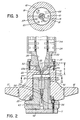
- the structure of the piston 14 is best illustrated in Figures 2 and 3 as comprising an axial bore 56 through which extends a vent rod 57 that is in threaded engagement with an insert 58 seated in the bore 56.
- the rod 57 passes through a seal structure 59, and then extends axially upwards through the propellant charge 16 received in the counterbore 15, through the gas vent 23a formed in the insert 23, and upwardly to a predetermined height X ( Figure 2) above the lower surface of the end wall 20 of the cylinder 19.
- three equiangularly spaced pressure transducers 61 are recessed in the top wall of the piston 14, these being connected to the exterior of the apparatus through suitable electrical wiring 62 passing through the flange 13 of the launching base 12 of the piston.
- the vent rod 57 is fabricated in a suitable electrically conductive material, and is utilized to transmit current to effect initiation of the propellant charge 16.
- an electrical connection 65 formed between the lower end of the vent rod 57 and the periphery of the flange 13, where it can be connected to external current supply means.
- a hot wire assembly 66 having three radial limbs of resistance wire is positioned between the vent rod 57 and surrounding portions of the end surface of the piston 14, the rod otherwise being insulated from the piston and from the cylinder assembly 17. It will be appreciated therefore that when current is applied to the connection 65 the hot wire assembly 66 will be heated and will effect initiation of the combustion of the propellant charge 16.
- the pressure transducers 61 monitor the pressure within the chamber 21 on a continuous basis.
- a velocity displacement transducer 34 is attached to the surface of the caisson to monitor displacements thereof.
- the cylinder bore 15 is loaded with a quantity of propellant charge 16 having combustion characteristics sufficient to generate the desired pressure in the chamber 21.
- the launch cylinder assembly 17 is then placed over the piston in the position shown in Figures 1 and 2 and loaded by the concrete rings 30 to provide a reaction mass of the desired magnitude.
- gas pressure in the chamber 21 increases very rapidly providing a force to launch the cylinder assembly 17 and its weight 30 vertically upwards, providing at the same time an equal and opposite downwardly acting reaction force upon the piston 14.
- This reaction force is of course coaxial with respect to the caisson 10 since the cylinder assembly is guided by the piston 14.
- the combustion gases are sealed within the chamber 21 since the vent 23a is closed by the vent rod 57 passing therethrough.
- the vent 23 is unblocked and permits escape of the combustion gases through the silencer 24.
- the flow of the hot combustion gases through the vent 23a rapidly erodes the material of the insert 23, widening the cross section of the vent 23a so that the gas pressure within the chamber 21 will dissipate relatively rapidly after combustion of the propellant 16 has been completed.
- Figure 4 shows schematically the arrangement after the cylinder assembly and the reaction mass have been launched. This will rise by no more than a few feet before beginning to descend again under the force of gravity. However before descent occurs, the surrounding mass of sand 31 will collapse under the plate 18 of the cylinder assembly and thus provide a cushion between this and the top of the caisson 10 when the cylinder assembly and reaction mass descend under the force of gravity. Thus impact damage to the caisson is avoided.
- the graph 40 in Figure 5 shows the change in pressure with time commencing with the initiation of combustion of the propellant charge as measured by the pressure transducer in the chamber 21, and the lower graph 41 shows the corresponding displacement of the top end of the caisson 10 as measured by the velocity transducer 34. It will be seen that as the pressure in the chamber 21 increases, the downwards displacement of the caisson 10 likewise increases, reaching a maximum at the same time as the chamber pressure, and thereafter diminishing, there being a residual displacement dx indicating that the frictional engagement between the caisson 10 and the surrounding ground formation has been stressed to failure point producing a permanent minor displacement of the caisson.
- the rate at which the pressure in the chamber 21 increases is a function of the characteristics of the propellant charge 16, and may be varied by appropriate selection of propellant materials.
- the desired reaction force should be developed over a duration of approximately 40 to 60 milliseconds which is almost 10 times longer than the duration of a force which could be achieved through impact of dropping a similar mass on top of the caisson 10.
- the duration over which the reaction force acts can be varied to some extent by variation in the length X by which the vent rod 57 projects. By increasing the dimension X, the duration of confinement of the combustion gases in the chamber 21 will be extended, and vice versa if the dimension X is reduced.
- the dimensions of the chamber 21 and the characteristics of the propellent charge 17 are preferably selected so that in operation a pressure of the order of 12,000 psi is developed in the chamber.
- a relief passage 70 is provided in the cylinder end wall 20.
- the relief passage is sealed by a rupture disc 71 which is designed to fracture at some predetermined pressure, e.g. 15,000 psi, and vent gases from the chamber 21 through a passage 72 into the silencer 24.
- the invention provides a method of introducing high energies into the caisson 10 without damaging the latter.
- Reaction forces in the range 400 to 600 tons can be achieved by using a reaction mass that is of no more than 32,000 pounds weight.
- the equipment consists essentially of the launching base 12, and the launch cylinder assembly 17, which is essentially of light weight and is easily transported.
- the concrete rings 30 forming the reaction mass weigh no more than 10,000 pounds each, and in fact may readily be cast in situ at the same time as the test caisson itself is cast, and thus need not be transported from one site to another. It will be appreciated that because of the relatively low weights of the components, no special heavy weight materials handling equipment is necessary for installation of the test apparatus.
- test procedure can also be used in conjunction with the CAPWAPC (trademark) program to determine the capacity and distribution of resistance forces between the caisson 10 and the ground formation.
- FIG. 6 use is made of a relatively small diameter piston and cylinder having a long stroke.
- the elongated cylinder 17a having reinforcing ribs 17b thereon is cast in place within the upper end of the caisson 10a.
- An elongated piston 14a is received within the cylinder 17a and is connected at its upper end to a launch plate 18a on which the concrete rings 30a forming the reaction mass are supported.
- the launch plate 18a is secured to the end of the piston by frangible bolts 42.
- a slow burning propellant is provided in the elongate chamber 16a.
- the test system of the present invention provides a means by which caissons and piles can be load tested in a much cheaper and more convenient manner than was hitherto possible.
- a relatively small mass e.g. 8 cubic meters of concrete
- a relatively large reaction force up to 1,000 tons or more
- onsite full scale load testing can be performed in a relatively simple and inexpensive manner.
- This produces the overall benefit of being able to check accurately the load bearing capacity of a foundation member with reference to its designed load. Since such testing reveals excess capacity, substantial cost saving can be effected by modifying the foundation design.
- the CAPWAPC program in conjunction with the above described test procedure it is possible to determine the distribution shaft resistance in an accurate manner so that the foundation design can be fine tuned to eliminate factors of ignorance, yielding a safe adequate design without the excess cost of overdesign.
- the reaction force is concentric to the longitudinal axis of the caisson.
- the test procedure can be applied to caissons or batter piles that are positioned in the ground at an angle to the vertical, since the reaction force developed is in the direction of the axis of the foundation element, and is not significantly influenced by gravity.
- test procedure can be applied to foundation elements that are installed in the ground or in underwater sites. In the latter, the fluid resistance of the water will act to augment the inertial forces of the reaction mass, and thus a smaller mass may be utilized.
Landscapes
- Physics & Mathematics (AREA)
- General Physics & Mathematics (AREA)
- Engineering & Computer Science (AREA)
- Aviation & Aerospace Engineering (AREA)
- Investigating Strength Of Materials By Application Of Mechanical Stress (AREA)
- Revetment (AREA)
- Silver Salt Photography Or Processing Solution Therefor (AREA)
- Testing Of Devices, Machine Parts, Or Other Structures Thereof (AREA)
- Investigation Of Foundation Soil And Reinforcement Of Foundation Soil By Compacting Or Drainage (AREA)
- Force Measurement Appropriate To Specific Purposes (AREA)
Abstract
Description
- This invention relates to a new or improved test system for caissons, piles and the like providing an improved process and apparatus for testing the load bearing capabilities of such inground foundation elements.
- The capacity of foundation elements such as caissons can be tested by either of two conventional techniques. In the first, a support structure is built spaced above the top end of the caisson and loaded with a large mass. For example steel beams and piles may be fabricated into a rough box-shaped structure which is then loaded with sand or concrete blocks. A hydraulic jack is then positioned between the top of the caisson and the underside of the support structure and is expanded to jack against the underside of the weighted structure and in this way apply a controllable downwardly directed reaction load to the caisson. Using this technique large reaction forces may be produced, but the equipment is cumbersome, and accordingly the test procedure is time consuming and expensive.
- The second conventional test method involves the use of two auxiliary foundation elements spaced one on each side of the caisson to be tested. A large beam is then positioned to span across the three inline foundation elements and attached to the auxiliary foundation elements. A hydraulic jack is then placed between the top of the caisson to be tested and the underside of the beam in the center of the span. The ends of the beam being anchored to the auxiliary foundation elements apply the upwardly directed force of the jack to these in tension, the downwards reaction force of the jack being applied to the foundation element to be tested. In this way a high reaction force may be obtained. However this test procedure is also time consuming and relatively expensive.
- The third method of testing involves testing the resistance of the pile to movement during application of a dynamic load. The pile to be tested is struck with a falling mass and instruments attached to the pile record the downward velocity and force produced in the pile. Analysis of the results will determine the portion of the resistance mobilized by the impact. In the case of piles or caissons which have a high resistance it is difficult to introduce enough energy into the pile to fully mobilize all of its resistance without damaging the pile top or causing a tension break in the pile. The falling mass, typically a large drop hammer, is bulky and cumbersome to use and requires large equipment to operate.
- Accordingly, because of the expense and inconvenience of known testing procedures for caissons and similar drilled pier foundation elements, very often full scale load testing of such foundations is not performed. Instead, the pier/soil friction values are estimated using laboratory testing and correlations with soil index properties. Depending upon the site soil conditions that are encountered, such theoretical and laboratory calculations may tend to significantly underestimate the overall shear strength and friction values of the soil. As a result, the design of foundations is often overly conservative, including excessively high safety factors. This then results in the cost of such foundations being unnecessarily expensive.
- Accordingly there is a clear need for a cheaper and more convenient system for testing foundation elements such as caissons and piers so that the foundation design criteria developed are not only more economical, but also more realistic and more reliable than those based upon laboratory testing procedures.
- Accordingly, the present invention provides a method for testing the load-bearing capacity of a columnar inground foundation element, comprising supporting an inertial mass of predetermined magnitude on the upper end of a columnar foundation element that is installed in the ground; generating in a chamber defined between the underside of the inertial mass and the upper end of said foundation element over a limited duration a fluid pressure sufficient to accelerate said inertial mass upwards away from the upper end of the foundation element and at the same time to produce a downwards reaction force of a predetermined desired magnitude on said element; controlling the rate of increase of said fluid pressure such that the reaction force does not damage the foundation element; and measuring both the magnitude of said downwards force and the response of said foundation element.
- The fluid pressure is preferably generated by the combustion of a propellant charge, with the inertial mass being guided to move upwards axially of the foundation element. The escape of the gases produced by the combustion is controlled in such a manner as to attenuate soundwaves produced by the combustion.
- Desirably, the upper end of the foundation element will be protected from impact by the inertial mass when it descends under gravity after the fluid pressure has been dissipated.
- The invention also provides apparatus for testing the load-bearing capacity of a columnar inground foundation element, comprising: a base adapted to be affixed coaxially on the upper end of said foundation element; a carrier configured to be seated coaxially on said base and adapted to support an inertial mass of a desired magnitude; chamber means defined between said base and said carrier and comprising a cylinder having opposite ends associated with said base and said carrier respectively, said chamber having a volume which increases as said carrier moves upwardly away from its seated position on said base; pressure generating means for producing a controlled rapid increase in fluid pressure in said chamber of a magnitude sufficient to accelerate upwards said carrier and inertial mass and to produce a corresponding downwards reaction force on said base; pressure transducer means to measure continuously the magnitude of said downwards force as a function of said fluid pressure; and displacement transducer means adapted to measure the response of the foundation element to such downwards force.
- Preferably the base has a central axial piston element received in a cylindrical bore opening from the underside of the carrier, the end of the piston being formed with a recess to receive a charge of a combustible propellant compound. The ignition means for this charge is arranged to be actuated from outside the cylinder. The inertial mass may be in the form of one or more toroidal rings, suitably of concrete, positioned around the exterior of the cylinder and thus aligned to the vertical axis of the foundation element.
- To prevent impact of the carrier upon the base when the carrier descends after having been accelerated upwards by the pressure of the propellant gases, provision may be made to interpose sand or gravel between the underside of the carrier and the top of the base. Thus, for example, an annual cavity may be provided surrounding the toroidal rings, and this cavity filled with gravel which will slump to spread under the carrier when the later is raised.
- The invention will further be described, by way of example only, with reference to the accompanying drawings wherein:
- Figure 1 is a somewhat schematic longitudinal sectional view of a presently preferred embodiment of test apparatus shown installed on the upper end of a drilled cast in place foundation element;
- Figure 2 shows a portion of Figure 1 to an enlarged scale;
- Figure 3 is a cross-section taken on the line III-III of Figure 2;
- Figure 4 is a somewhat schematic view illustrating the testing apparatus in operation;
- Figure 5 is a graph illustrating the force generated and the displacement of the foundation element over time during operation of the testing apparatus; and
- Figure 6 is a longitudinal sectional view of a modified construction of testing apparatus.
- Referring to Figure 1, a cast in place inground foundation column or
cassion 10 that is to be tested has a disc-shaped steel plate 11 grouted to its upper end. A launchingbase 12 is bolted on top of the steel plate so that it is axially aligned with thecaisson 10, the base having anannular flange 13 at its lower end, and an upwardly projectingpiston 14 that is axially aligned with thecaisson 10. The piston has acentral counterbore 15 opening from its upper face to receive apropellant charge 16. - As is more clearly shown in Figure 2, a
launch cylinder assembly 17 has a radially extendingplate 18 at its lower end adapted to rest upon theflange 13 of the launching base as seen in Figure 1, and acylindrical portion 19 projecting axially upwards beyond theplate 18 and terminating in an end wall 20. A cylindricalexpandable chamber 21 is thus defined between this end wall 20 of the cylinder assembly, and the upper end of thepiston 14. - The launching
base 12 and thecylinder assembly 17 are preferably fabricated in steel, there being acopper gas seal 22 andpiston rings 51 of steel positioned to provide sealing between the cooperating cylindrical walls. Aninsert 23 is provided coaxially in a recess in the end wall 20 of the cylinder and defines anaxial gas vent 23a extending therethrough. Theinsert 23 is fabricated in a suitable eroding combustible material such as copper and leads to acylindrical silencer 24 positioned on top of the cylinder and fastened thereto bybolts 25. A replaceableannular throat 52 is seated above theinsert 23 and has a conically wideningbore 53 that communicates with agas passage 26 in the lower end of the silencer. Thegas passage 26 increases in cross section upwardly, is in register with thegas vent 23a, and is in communication with the interior of thesilencer 24 which incorporates suitable sound attenuating means such as a system ofbaffles 54. Thesilencer 24 is generally of cylindrical form and has an outer diameter that corresponds to the outer diameter of thecylindrical portion 19 of thecylinder assembly 17. - The upper side of the
plate portion 18 of the launch cylinder is flat and is designed to provide a seat to support a reaction mass which is in the form of a plurality oftoroidal concrete rings 30, these rings being aligned to the axis of thecaisson 10 by thecylinder 19 andsilencer 24. The above- described structure is surrounded by a mass of loose sand or gravel 31 that is contained within acylindrical wall 32 spaced concentrically with respect to therings 30. Thiswall 32 is supported on its outer lower side by a ring ofbackfill material 33, such material also surrounding the upper end of thecaisson 10. - The structure of the
piston 14 is best illustrated in Figures 2 and 3 as comprising anaxial bore 56 through which extends avent rod 57 that is in threaded engagement with aninsert 58 seated in thebore 56. Therod 57 passes through aseal structure 59, and then extends axially upwards through thepropellant charge 16 received in thecounterbore 15, through thegas vent 23a formed in theinsert 23, and upwardly to a predetermined height X (Figure 2) above the lower surface of the end wall 20 of thecylinder 19. - To monitor the pressure within the cylinder, three equiangularly spaced
pressure transducers 61 are recessed in the top wall of thepiston 14, these being connected to the exterior of the apparatus through suitableelectrical wiring 62 passing through theflange 13 of the launchingbase 12 of the piston. - The
vent rod 57 is fabricated in a suitable electrically conductive material, and is utilized to transmit current to effect initiation of thepropellant charge 16. To this end there is anelectrical connection 65 formed between the lower end of thevent rod 57 and the periphery of theflange 13, where it can be connected to external current supply means. Ahot wire assembly 66 having three radial limbs of resistance wire is positioned between thevent rod 57 and surrounding portions of the end surface of thepiston 14, the rod otherwise being insulated from the piston and from thecylinder assembly 17. It will be appreciated therefore that when current is applied to theconnection 65 thehot wire assembly 66 will be heated and will effect initiation of the combustion of thepropellant charge 16. - The
pressure transducers 61 monitor the pressure within thechamber 21 on a continuous basis. Avelocity displacement transducer 34 is attached to the surface of the caisson to monitor displacements thereof. - In use, the
cylinder bore 15 is loaded with a quantity ofpropellant charge 16 having combustion characteristics sufficient to generate the desired pressure in thechamber 21. Thelaunch cylinder assembly 17 is then placed over the piston in the position shown in Figures 1 and 2 and loaded by the concrete rings 30 to provide a reaction mass of the desired magnitude. Upon ignition of the propellant charge, gas pressure in thechamber 21 increases very rapidly providing a force to launch thecylinder assembly 17 and itsweight 30 vertically upwards, providing at the same time an equal and opposite downwardly acting reaction force upon thepiston 14. This reaction force is of course coaxial with respect to thecaisson 10 since the cylinder assembly is guided by thepiston 14. - At commencement of combustion, the combustion gases are sealed within the
chamber 21 since thevent 23a is closed by thevent rod 57 passing therethrough. However once the gas pressure has raised thelaunch cylinder assembly 17 by the distance X, then thevent 23 is unblocked and permits escape of the combustion gases through thesilencer 24. The flow of the hot combustion gases through thevent 23a rapidly erodes the material of theinsert 23, widening the cross section of thevent 23a so that the gas pressure within thechamber 21 will dissipate relatively rapidly after combustion of thepropellant 16 has been completed. - Figure 4 shows schematically the arrangement after the cylinder assembly and the reaction mass have been launched. This will rise by no more than a few feet before beginning to descend again under the force of gravity. However before descent occurs, the surrounding mass of sand 31 will collapse under the
plate 18 of the cylinder assembly and thus provide a cushion between this and the top of thecaisson 10 when the cylinder assembly and reaction mass descend under the force of gravity. Thus impact damage to the caisson is avoided. - The
graph 40 in Figure 5 shows the change in pressure with time commencing with the initiation of combustion of the propellant charge as measured by the pressure transducer in thechamber 21, and thelower graph 41 shows the corresponding displacement of the top end of thecaisson 10 as measured by thevelocity transducer 34. It will be seen that as the pressure in thechamber 21 increases, the downwards displacement of thecaisson 10 likewise increases, reaching a maximum at the same time as the chamber pressure, and thereafter diminishing, there being a residual displacement dx indicating that the frictional engagement between thecaisson 10 and the surrounding ground formation has been stressed to failure point producing a permanent minor displacement of the caisson. - The rate at which the pressure in the
chamber 21 increases is a function of the characteristics of thepropellant charge 16, and may be varied by appropriate selection of propellant materials. Preferably the desired reaction force should be developed over a duration of approximately 40 to 60 milliseconds which is almost 10 times longer than the duration of a force which could be achieved through impact of dropping a similar mass on top of thecaisson 10. The duration over which the reaction force acts can be varied to some extent by variation in the length X by which thevent rod 57 projects. By increasing the dimension X, the duration of confinement of the combustion gases in thechamber 21 will be extended, and vice versa if the dimension X is reduced. - The dimensions of the
chamber 21 and the characteristics of thepropellent charge 17 are preferably selected so that in operation a pressure of the order of 12,000 psi is developed in the chamber. To prevent damage which might be caused by excessive over-pressure, arelief passage 70 is provided in the cylinder end wall 20. The relief passage is sealed by a rupture disc 71 which is designed to fracture at some predetermined pressure, e.g. 15,000 psi, and vent gases from thechamber 21 through apassage 72 into thesilencer 24. - Thus the invention provides a method of introducing high energies into the
caisson 10 without damaging the latter. Reaction forces in the range 400 to 600 tons can be achieved by using a reaction mass that is of no more than 32,000 pounds weight. The equipment consists essentially of the launchingbase 12, and thelaunch cylinder assembly 17, which is essentially of light weight and is easily transported. The concrete rings 30 forming the reaction mass weigh no more than 10,000 pounds each, and in fact may readily be cast in situ at the same time as the test caisson itself is cast, and thus need not be transported from one site to another. It will be appreciated that because of the relatively low weights of the components, no special heavy weight materials handling equipment is necessary for installation of the test apparatus. - In addition to utilizing the instrumentation described above to produce an onsite graph or displacement and force, the above described test procedure can also be used in conjunction with the CAPWAPC (trademark) program to determine the capacity and distribution of resistance forces between the
caisson 10 and the ground formation. - In an alternative arrangement illustrated in Figure 6, use is made of a relatively small diameter piston and cylinder having a long stroke. In this arrangement the
elongated cylinder 17a having reinforcingribs 17b thereon is cast in place within the upper end of thecaisson 10a. An elongated piston 14a is received within thecylinder 17a and is connected at its upper end to alaunch plate 18a on which the concrete rings 30a forming the reaction mass are supported. Thelaunch plate 18a is secured to the end of the piston byfrangible bolts 42. A slow burning propellant is provided in theelongate chamber 16a. When the propellant is ignited, the gas pressure increases until a desired level has been reached at which thebolts 42 fail, whereupon the reaction force of this gas pressure is applied to thecaisson 10a. With this arrangement therefore the reaction force would be applied to the caisson over a shorter durational though still at a much slower rate than were the energy transferred to the caisson through the impact of a falling body. - The test system of the present invention provides a means by which caissons and piles can be load tested in a much cheaper and more convenient manner than was hitherto possible. By launching a relatively small mass (e.g. 8 cubic meters of concrete) into the air from a rest position on top of the caisson, a relatively large reaction force (up to 1,000 tons or more) can be developed over a relatively long duration such that the energy input to the caisson is not at a rate that will result in destruction of the latter. Thus onsite full scale load testing can be performed in a relatively simple and inexpensive manner. This produces the overall benefit of being able to check accurately the load bearing capacity of a foundation member with reference to its designed load. Since such testing reveals excess capacity, substantial cost saving can be effected by modifying the foundation design. By utilizing the CAPWAPC program in conjunction with the above described test procedure it is possible to determine the distribution shaft resistance in an accurate manner so that the foundation design can be fine tuned to eliminate factors of ignorance, yielding a safe adequate design without the excess cost of overdesign.
- It will be appreciated that because of the configuration of the above described apparatus, the reaction force is concentric to the longitudinal axis of the caisson. Furthermore, the test procedure can be applied to caissons or batter piles that are positioned in the ground at an angle to the vertical, since the reaction force developed is in the direction of the axis of the foundation element, and is not significantly influenced by gravity.
- The test procedure can be applied to foundation elements that are installed in the ground or in underwater sites. In the latter, the fluid resistance of the water will act to augment the inertial forces of the reaction mass, and thus a smaller mass may be utilized.
- Furthermore it will be appreciated that the design could be modified to make use of atmospheric air pressure to develop the reaction force, although this would entail utilizing a reaction member of a very large surface area.
Claims (14)
supporting an inertial mass of predetermined magnitude on the upper end of a columnar foundation element that is installed in the ground;
generating in a chamber defined between the underside of the inertial mass and the upper end of said foundation element over a limited duration a fluid pressure sufficient to accelerate said inertial mass upwards away from the upper end of the foundation element and at the same time to produce a downwards reaction force of a predetermined desired magnitude on said element;
controlling the rate of increase of said fluid pressure such that the reaction force does not damage the foundation element; and
measuring both the magnitude of said downwards force and the response of said foundation element.
a base adapted to be affixed coaxially on the upper end of said foundation element;
a carrier configured to be seated coaxially on said base and adapted to support an inertial mass of a desired magnitude;
chamber means defined between said base and said carrier and comprising a cylinder having opposite ends associated with said base and said carrier respectively, said chamber having a volume which increases as said carrier moves upwardly away from its seated position on said base;
pressure generating means for producing a controlled rapid increase in fluid pressure in said chamber of a magnitude sufficient to accelerate upwards said carrier and inertial mass and to produce a corresponding downwards reaction force on said base;
pressure transducer means to measure continuously the magnitude of said downwards force as a function of said fluid pressure;
and displacement transducer means adapted to measure the response of the foundation element to such downwards force.
Priority Applications (1)
| Application Number | Priority Date | Filing Date | Title |
|---|---|---|---|
| AT89200860T ATE101268T1 (en) | 1988-04-07 | 1989-04-05 | TESTING SYSTEM FOR CAISSONS AND PILES. |
Applications Claiming Priority (2)
| Application Number | Priority Date | Filing Date | Title |
|---|---|---|---|
| CA563495 | 1988-04-07 | ||
| CA000563495A CA1296925C (en) | 1988-04-07 | 1988-04-07 | Test system for caissons and piles |
Publications (3)
| Publication Number | Publication Date |
|---|---|
| EP0336519A2 true EP0336519A2 (en) | 1989-10-11 |
| EP0336519A3 EP0336519A3 (en) | 1991-07-03 |
| EP0336519B1 EP0336519B1 (en) | 1994-02-02 |
Family
ID=4137786
Family Applications (1)
| Application Number | Title | Priority Date | Filing Date |
|---|---|---|---|
| EP89200860A Expired - Lifetime EP0336519B1 (en) | 1988-04-07 | 1989-04-05 | Test system for caissons and piles |
Country Status (7)
| Country | Link |
|---|---|
| US (1) | US4845996A (en) |
| EP (1) | EP0336519B1 (en) |
| JP (1) | JPH0670602B2 (en) |
| AT (1) | ATE101268T1 (en) |
| CA (1) | CA1296925C (en) |
| DE (1) | DE68912806T2 (en) |
| ES (1) | ES2050779T3 (en) |
Families Citing this family (49)
| Publication number | Priority date | Publication date | Assignee | Title |
|---|---|---|---|---|
| US5259240A (en) * | 1992-04-03 | 1993-11-09 | Exxon Production Research Company | Device for in situ testing of soils that includes a vent valve adapted to close at a predetermined depth during installation |
| US6349590B1 (en) * | 1997-09-15 | 2002-02-26 | Yee Kong Wai | Method and apparatus for estimating load bearing capacity of piles |
| US6129487A (en) * | 1998-07-30 | 2000-10-10 | Bermingham Construction Limited | Underwater pile driving tool |
| US7192681B2 (en) | 2001-07-05 | 2007-03-20 | Fuji Photo Film Co., Ltd. | Positive photosensitive composition |
| JP4448705B2 (en) | 2004-02-05 | 2010-04-14 | 富士フイルム株式会社 | Photosensitive composition and pattern forming method using the photosensitive composition |
| WO2006015278A2 (en) * | 2004-07-30 | 2006-02-09 | Loadtest, Inc. | Method and apparatus for automatic load testing using bi-directional testing |
| JP4602714B2 (en) | 2004-08-19 | 2010-12-22 | 株式会社ティラド | Heat exchanger |
| JP4469692B2 (en) | 2004-09-14 | 2010-05-26 | 富士フイルム株式会社 | Photosensitive composition, compound used for photosensitive composition, and pattern formation method using the photosensitive composition |
| JP4474256B2 (en) | 2004-09-30 | 2010-06-02 | 富士フイルム株式会社 | Resist composition and pattern forming method using the same |
| JP4452632B2 (en) | 2005-01-24 | 2010-04-21 | 富士フイルム株式会社 | Photosensitive composition, compound used for photosensitive composition, and pattern formation method using the photosensitive composition |
| US7947421B2 (en) | 2005-01-24 | 2011-05-24 | Fujifilm Corporation | Positive resist composition for immersion exposure and pattern-forming method using the same |
| JP4562537B2 (en) | 2005-01-28 | 2010-10-13 | 富士フイルム株式会社 | Photosensitive composition, compound used for photosensitive composition, and pattern formation method using the photosensitive composition |
| US8741537B2 (en) | 2005-03-04 | 2014-06-03 | Fujifilm Corporation | Positive resist composition and pattern-forming method using the same |
| US7960087B2 (en) | 2005-03-11 | 2011-06-14 | Fujifilm Corporation | Positive photosensitive composition and pattern-forming method using the same |
| JP4579019B2 (en) | 2005-03-17 | 2010-11-10 | 富士フイルム株式会社 | Positive resist composition and pattern forming method using the resist composition |
| EP1720072B1 (en) | 2005-05-01 | 2019-06-05 | Rohm and Haas Electronic Materials, L.L.C. | Compositons and processes for immersion lithography |
| JP4724465B2 (en) | 2005-05-23 | 2011-07-13 | 富士フイルム株式会社 | Photosensitive composition and pattern forming method using the photosensitive composition |
| JP4861767B2 (en) | 2005-07-26 | 2012-01-25 | 富士フイルム株式会社 | Positive resist composition and pattern forming method using the same |
| JP4695941B2 (en) | 2005-08-19 | 2011-06-08 | 富士フイルム株式会社 | Positive resist composition for immersion exposure and pattern forming method using the same |
| TWI403843B (en) | 2005-09-13 | 2013-08-01 | Fujifilm Corp | Positive resist composition and pattern-forming method using the same |
| EP1795960B1 (en) | 2005-12-09 | 2019-06-05 | Fujifilm Corporation | Positive resist composition, pattern forming method using the positive resist composition, use of the positive resit composition |
| JP4911456B2 (en) | 2006-11-21 | 2012-04-04 | 富士フイルム株式会社 | POSITIVE PHOTOSENSITIVE COMPOSITION, POLYMER COMPOUND USED FOR POSITIVE PHOTOSENSITIVE COMPOSITION, METHOD FOR PRODUCING THE POLYMER COMPOUND, AND PATTERN FORMATION METHOD USING POSITIVE SENSITIVE COMPOSITION |
| JP4554665B2 (en) | 2006-12-25 | 2010-09-29 | 富士フイルム株式会社 | PATTERN FORMATION METHOD, POSITIVE RESIST COMPOSITION FOR MULTIPLE DEVELOPMENT USED FOR THE PATTERN FORMATION METHOD, NEGATIVE DEVELOPMENT SOLUTION USED FOR THE PATTERN FORMATION METHOD, AND NEGATIVE DEVELOPMENT RINSE SOLUTION USED FOR THE PATTERN FORMATION METHOD |
| EP1962139A1 (en) | 2007-02-23 | 2008-08-27 | FUJIFILM Corporation | Negative resist composition and pattern forming method using the same |
| EP1975714A1 (en) | 2007-03-28 | 2008-10-01 | FUJIFILM Corporation | Positive resist composition and pattern forming method |
| EP1975716B1 (en) | 2007-03-28 | 2013-05-15 | Fujifilm Corporation | Positive resist composition and pattern forming method |
| JP4562784B2 (en) | 2007-04-13 | 2010-10-13 | 富士フイルム株式会社 | PATTERN FORMING METHOD, RESIST COMPOSITION, DEVELOPER AND RINSE SOLUTION USED FOR THE PATTERN FORMING METHOD |
| EP1980911A3 (en) | 2007-04-13 | 2009-06-24 | FUJIFILM Corporation | Pattern forming method, resist composition to be used in the pattern forming method, negative developing solution to be used in the pattern forming method and rinsing solution for negative development to be used in the pattern forming method |
| JP4617337B2 (en) | 2007-06-12 | 2011-01-26 | 富士フイルム株式会社 | Pattern formation method |
| JP2008311474A (en) | 2007-06-15 | 2008-12-25 | Fujifilm Corp | Pattern formation method |
| JP2009053688A (en) | 2007-07-30 | 2009-03-12 | Fujifilm Corp | Positive resist composition and pattern forming method |
| JP5066405B2 (en) | 2007-08-02 | 2012-11-07 | 富士フイルム株式会社 | Resist composition for electron beam, X-ray or EUV, and pattern forming method using the composition |
| US8110333B2 (en) | 2007-08-03 | 2012-02-07 | Fujifilm Corporation | Resist composition containing novel sulfonium compound, pattern-forming method using the resist composition, and novel sulfonium compound |
| JP5449675B2 (en) | 2007-09-21 | 2014-03-19 | 富士フイルム株式会社 | Photosensitive composition, pattern forming method using the photosensitive composition, and compound used in the photosensitive composition |
| JP5150296B2 (en) | 2008-02-13 | 2013-02-20 | 富士フイルム株式会社 | Positive resist composition for electron beam, X-ray or EUV and pattern forming method using the same |
| US9046773B2 (en) | 2008-03-26 | 2015-06-02 | Fujifilm Corporation | Actinic ray-sensitive or radiation-sensitive resin composition, pattern forming method using the same, polymerizable compound and polymer compound obtained by polymerizing the polymerizable compound |
| JP5997873B2 (en) | 2008-06-30 | 2016-09-28 | 富士フイルム株式会社 | Photosensitive composition and pattern forming method using the same |
| JP5244711B2 (en) | 2008-06-30 | 2013-07-24 | 富士フイルム株式会社 | Actinic ray-sensitive or radiation-sensitive resin composition and pattern forming method using the same |
| JP5746818B2 (en) | 2008-07-09 | 2015-07-08 | 富士フイルム株式会社 | Actinic ray-sensitive or radiation-sensitive resin composition and pattern forming method using the same |
| RU2512672C2 (en) | 2008-11-21 | 2014-04-10 | Хадар МАГАЛИ | Chipping mechanism |
| US8795944B2 (en) | 2008-12-12 | 2014-08-05 | Fujifilm Corporation | Actinic ray-sensitive or radiation-sensitive resin composition and pattern forming method using the composition |
| EP2196462B1 (en) | 2008-12-12 | 2011-09-28 | Fujifilm Corporation | Polymerizable compound, lactone-containing compound, method for manufacturing lactone-containing compound and polymer compound obtained by polymerizing the polymerizable compound |
| JP5377172B2 (en) | 2009-03-31 | 2013-12-25 | 富士フイルム株式会社 | Actinic ray-sensitive or radiation-sensitive resin composition and pattern forming method using the same |
| CA2732380C (en) * | 2010-02-22 | 2016-10-04 | Ben Kasprick | Method and apparatus for load testing a pile |
| JP5712099B2 (en) | 2010-09-28 | 2015-05-07 | 富士フイルム株式会社 | Resist composition, and resist film and pattern forming method using the same |
| CN105525635B (en) * | 2016-01-18 | 2017-09-15 | 交通运输部公路科学研究所 | The loading device detected for pile foundation axial bearing capacity |
| CN106049562B (en) * | 2016-07-18 | 2018-02-16 | 昆山市建设工程质量检测中心 | A kind of height of the fall adjusting means for pile foundation high strain monitoring |
| CN113166327A (en) | 2018-11-22 | 2021-07-23 | 富士胶片株式会社 | Actinic-ray-or radiation-sensitive resin composition, resist film, pattern forming method, and method for manufacturing electronic device |
| CN112525711B (en) * | 2020-11-26 | 2023-08-22 | 中国电建集团成都勘测设计研究院有限公司 | Bidirectional deep soil mechanical parameter in-situ testing device and testing structure |
Family Cites Families (17)
| Publication number | Priority date | Publication date | Assignee | Title |
|---|---|---|---|---|
| US2674876A (en) * | 1950-08-28 | 1954-04-13 | Western Foundation Corp | Pile testing means |
| US3248924A (en) * | 1961-11-22 | 1966-05-03 | William W Boynton | System for dynamic loading |
| FR92879E (en) * | 1966-09-23 | 1969-01-10 | Louis Francois | Method and apparatus for measuring the modulus of deformation of a material and the stresses in that material. |
| GB1206396A (en) * | 1966-10-28 | 1970-09-23 | Wykeham Farrance Engineering L | Improvements relating to geological sample testing apparatus |
| US3535919A (en) * | 1968-12-02 | 1970-10-27 | John P Budlong | Dynamic determination of pile load capacity |
| DE2139735C3 (en) * | 1971-08-07 | 1974-02-21 | Rheinmetall Gmbh, 4000 Duesseldorf | Device for simulating the shot stress of gun barrels |
| US3798962A (en) * | 1972-04-19 | 1974-03-26 | Atomic Energy Commission | Method for predicting movements of structural members emplaced in the earth |
| DE2439782B1 (en) * | 1974-08-20 | 1975-10-30 | Fa. Franz Gloetzl, 7501 Forchheim | Force measuring device for anchors in construction |
| US3960008A (en) * | 1974-12-12 | 1976-06-01 | Goble George G | Pile capacity testing means |
| FR2461066A1 (en) * | 1979-07-09 | 1981-01-30 | Coelus Gaspar | METHOD AND APPARATUS FOR DYNAMIC PIEUX TESTING |
| US4347743A (en) * | 1980-09-18 | 1982-09-07 | Pile Dynamics, Inc. | Accelerometer mounting assembly |
| US4379401A (en) * | 1981-08-28 | 1983-04-12 | The United States Of America As Represented By The Secretary Of The Army | System for measuring plate deformation produced by explosive shock waves, and motion-sensing accelerometer transducer used therein |
| US4479378A (en) * | 1982-09-23 | 1984-10-30 | The United States Of America As Represented By The Secretary Of The Navy | Method and system for determining effect of underwater explosion on submerged structures |
| US4474052A (en) * | 1982-12-13 | 1984-10-02 | E. I. Du Pont De Nemours And Company | Laboratory barricade |
| JPS6080619A (en) * | 1983-10-06 | 1985-05-08 | Inayoshi Kogyo:Kk | Method and apparatus for measuring bearing capacity of pile in piling work |
| US4619218A (en) * | 1984-01-30 | 1986-10-28 | Hen-Jac, Inc. | Embedment anchor |
| US4586366A (en) * | 1984-03-14 | 1986-05-06 | Milberger Lionel J | Method and apparatus for measuring driving resistance and velocity of piles during driving |
-
1988
- 1988-04-07 CA CA000563495A patent/CA1296925C/en not_active Expired - Lifetime
- 1988-05-04 US US07/190,163 patent/US4845996A/en not_active Expired - Lifetime
-
1989
- 1989-04-05 ES ES89200860T patent/ES2050779T3/en not_active Expired - Lifetime
- 1989-04-05 AT AT89200860T patent/ATE101268T1/en not_active IP Right Cessation
- 1989-04-05 DE DE68912806T patent/DE68912806T2/en not_active Expired - Fee Related
- 1989-04-05 EP EP89200860A patent/EP0336519B1/en not_active Expired - Lifetime
- 1989-04-07 JP JP1087126A patent/JPH0670602B2/en not_active Expired - Lifetime
Also Published As
| Publication number | Publication date |
|---|---|
| DE68912806T2 (en) | 1994-08-11 |
| ES2050779T3 (en) | 1994-06-01 |
| EP0336519B1 (en) | 1994-02-02 |
| JPH0228531A (en) | 1990-01-30 |
| JPH0670602B2 (en) | 1994-09-07 |
| ATE101268T1 (en) | 1994-02-15 |
| CA1296925C (en) | 1992-03-10 |
| EP0336519A3 (en) | 1991-07-03 |
| US4845996A (en) | 1989-07-11 |
| DE68912806D1 (en) | 1994-03-17 |
Similar Documents
| Publication | Publication Date | Title |
|---|---|---|
| EP0336519B1 (en) | Test system for caissons and piles | |
| Holeyman | Keynote lecture: Technology of pile dynamic testing | |
| US4614110A (en) | Device for testing the load-bearing capacity of concrete-filled earthen shafts | |
| Engineer | An innovative approach to load testing of high capacity piles | |
| Broms | Lateral resistance of piles in cohesive soils | |
| US3946601A (en) | Method of load testing foundations | |
| FI92235B (en) | System for pushing the anchor to the ground | |
| US4132082A (en) | Piling | |
| Abdul-Hussain et al. | Blast induced lateral earth pressures on retaining structures with sand backfill | |
| US20160216387A1 (en) | System and Method for Accelerating a Mass Using a Pressure Produced by a Detonation | |
| JP4513092B2 (en) | Rapid loading test equipment for ground anchors | |
| Miyasaka et al. | Rapid load test on high bearing capacity piles | |
| Beim et al. | Dynamic testing of enlarged base Franki piles | |
| CN220305009U (en) | Test device for anchoring arch bearing structure of broken rock mass | |
| Sloan | Dynamic Bearing Capacity of Soils: Dynamic Loading Machine and Preliminary Small-scale Footing Tests | |
| Janes et al. | Proposed ASTM Standard test for piles under rapid axial compressive load with its draft paper “Long period dynamic load testing ASTM standard draft” presented to the seminar for technical discussion | |
| Janes et al. | Proposed ASTM Standard test for piles under rapid axial compressive load with its draft paper" Long period dynamic load | |
| Matsumoto et al. | Trend of research and practice of pile foundations in Japan | |
| El-Deeb et al. | Response measurements on an echinodome subjected to explosive loading | |
| Kimura et al. | Experimental study of STATNAMIC load test by air-pressure based loading apparatus | |
| JPS5836063Y2 (en) | Jishintan Sayokashinouchi | |
| Team | Lateral STATNAMIC Testing | |
| Robertson et al. | Lateral STATNAMIC load testing: A new method for evaluating lateral load capacity | |
| WO1996020314A1 (en) | Transport means such as a vessel or vehicle, provided with a device for compacting ground | |
| Davies | Laboratory and centrifuge modelling of impact loading on buried structures |
Legal Events
| Date | Code | Title | Description |
|---|---|---|---|
| PUAI | Public reference made under article 153(3) epc to a published international application that has entered the european phase |
Free format text: ORIGINAL CODE: 0009012 |
|
| AK | Designated contracting states |
Kind code of ref document: A2 Designated state(s): AT BE CH DE ES FR GB GR IT LI LU NL SE |
|
| PUAL | Search report despatched |
Free format text: ORIGINAL CODE: 0009013 |
|
| AK | Designated contracting states |
Kind code of ref document: A3 Designated state(s): AT BE CH DE ES FR GB GR IT LI LU NL SE |
|
| 17P | Request for examination filed |
Effective date: 19911220 |
|
| 17Q | First examination report despatched |
Effective date: 19921001 |
|
| GRAA | (expected) grant |
Free format text: ORIGINAL CODE: 0009210 |
|
| AK | Designated contracting states |
Kind code of ref document: B1 Designated state(s): AT BE CH DE ES FR GB GR IT LI LU NL SE |
|
| PG25 | Lapsed in a contracting state [announced via postgrant information from national office to epo] |
Ref country code: IT Free format text: LAPSE BECAUSE OF FAILURE TO SUBMIT A TRANSLATION OF THE DESCRIPTION OR TO PAY THE FEE WITHIN THE PRE;WARNING: LAPSES OF ITALIAN PATENTS WITH EFFECTIVE DATE BEFORE 2007 MAY HAVE OCCURRED AT ANY TIME BEFORE 2007. THE CORRECT EFFECTIVE DATE MAY BE DIFFERENT FROM THE ONE RECORDED.SCRIBED TIME-LIMIT Effective date: 19940202 Ref country code: GR Free format text: LAPSE BECAUSE OF FAILURE TO SUBMIT A TRANSLATION OF THE DESCRIPTION OR TO PAY THE FEE WITHIN THE PRESCRIBED TIME-LIMIT Effective date: 19940202 |
|
| REF | Corresponds to: |
Ref document number: 101268 Country of ref document: AT Date of ref document: 19940215 Kind code of ref document: T |
|
| REF | Corresponds to: |
Ref document number: 68912806 Country of ref document: DE Date of ref document: 19940317 |
|
| PG25 | Lapsed in a contracting state [announced via postgrant information from national office to epo] |
Ref country code: LU Free format text: LAPSE BECAUSE OF NON-PAYMENT OF DUE FEES Effective date: 19940430 |
|
| REG | Reference to a national code |
Ref country code: ES Ref legal event code: FG2A Ref document number: 2050779 Country of ref document: ES Kind code of ref document: T3 |
|
| ET | Fr: translation filed | ||
| PLBE | No opposition filed within time limit |
Free format text: ORIGINAL CODE: 0009261 |
|
| STAA | Information on the status of an ep patent application or granted ep patent |
Free format text: STATUS: NO OPPOSITION FILED WITHIN TIME LIMIT |
|
| 26N | No opposition filed | ||
| EAL | Se: european patent in force in sweden |
Ref document number: 89200860.8 |
|
| REG | Reference to a national code |
Ref country code: GB Ref legal event code: IF02 |
|
| PGFP | Annual fee paid to national office [announced via postgrant information from national office to epo] |
Ref country code: AT Payment date: 20030313 Year of fee payment: 15 |
|
| PGFP | Annual fee paid to national office [announced via postgrant information from national office to epo] |
Ref country code: CH Payment date: 20030331 Year of fee payment: 15 |
|
| PGFP | Annual fee paid to national office [announced via postgrant information from national office to epo] |
Ref country code: FR Payment date: 20030408 Year of fee payment: 15 |
|
| PGFP | Annual fee paid to national office [announced via postgrant information from national office to epo] |
Ref country code: ES Payment date: 20030411 Year of fee payment: 15 |
|
| PGFP | Annual fee paid to national office [announced via postgrant information from national office to epo] |
Ref country code: SE Payment date: 20030416 Year of fee payment: 15 |
|
| PGFP | Annual fee paid to national office [announced via postgrant information from national office to epo] |
Ref country code: DE Payment date: 20030424 Year of fee payment: 15 |
|
| PGFP | Annual fee paid to national office [announced via postgrant information from national office to epo] |
Ref country code: BE Payment date: 20030428 Year of fee payment: 15 |
|
| PG25 | Lapsed in a contracting state [announced via postgrant information from national office to epo] |
Ref country code: AT Free format text: LAPSE BECAUSE OF NON-PAYMENT OF DUE FEES Effective date: 20040405 |
|
| PG25 | Lapsed in a contracting state [announced via postgrant information from national office to epo] |
Ref country code: ES Free format text: LAPSE BECAUSE OF NON-PAYMENT OF DUE FEES Effective date: 20040406 Ref country code: SE Free format text: LAPSE BECAUSE OF NON-PAYMENT OF DUE FEES Effective date: 20040406 |
|
| PG25 | Lapsed in a contracting state [announced via postgrant information from national office to epo] |
Ref country code: LI Free format text: LAPSE BECAUSE OF NON-PAYMENT OF DUE FEES Effective date: 20040430 Ref country code: CH Free format text: LAPSE BECAUSE OF NON-PAYMENT OF DUE FEES Effective date: 20040430 Ref country code: BE Free format text: LAPSE BECAUSE OF NON-PAYMENT OF DUE FEES Effective date: 20040430 |
|
| BERE | Be: lapsed |
Owner name: *BERMINGHAMMER CORP. LTD Effective date: 20040430 |
|
| PG25 | Lapsed in a contracting state [announced via postgrant information from national office to epo] |
Ref country code: DE Free format text: LAPSE BECAUSE OF NON-PAYMENT OF DUE FEES Effective date: 20041103 |
|
| EUG | Se: european patent has lapsed | ||
| REG | Reference to a national code |
Ref country code: CH Ref legal event code: PL |
|
| PG25 | Lapsed in a contracting state [announced via postgrant information from national office to epo] |
Ref country code: FR Free format text: LAPSE BECAUSE OF NON-PAYMENT OF DUE FEES Effective date: 20041231 |
|
| REG | Reference to a national code |
Ref country code: FR Ref legal event code: ST |
|
| REG | Reference to a national code |
Ref country code: ES Ref legal event code: FD2A Effective date: 20040406 |
|
| PGFP | Annual fee paid to national office [announced via postgrant information from national office to epo] |
Ref country code: GB Payment date: 20080326 Year of fee payment: 20 |
|
| PGFP | Annual fee paid to national office [announced via postgrant information from national office to epo] |
Ref country code: NL Payment date: 20080430 Year of fee payment: 20 |
|
| REG | Reference to a national code |
Ref country code: GB Ref legal event code: PE20 Expiry date: 20090404 |
|
| PG25 | Lapsed in a contracting state [announced via postgrant information from national office to epo] |
Ref country code: NL Free format text: LAPSE BECAUSE OF EXPIRATION OF PROTECTION Effective date: 20090405 |
|
| NLV7 | Nl: ceased due to reaching the maximum lifetime of a patent |
Effective date: 20090405 |
|
| PG25 | Lapsed in a contracting state [announced via postgrant information from national office to epo] |
Ref country code: GB Free format text: LAPSE BECAUSE OF EXPIRATION OF PROTECTION Effective date: 20090404 |