EP0336509B1 - Codeur hybride pour signaux vidéos - Google Patents
Codeur hybride pour signaux vidéos Download PDFInfo
- Publication number
- EP0336509B1 EP0336509B1 EP89200828A EP89200828A EP0336509B1 EP 0336509 B1 EP0336509 B1 EP 0336509B1 EP 89200828 A EP89200828 A EP 89200828A EP 89200828 A EP89200828 A EP 89200828A EP 0336509 B1 EP0336509 B1 EP 0336509B1
- Authority
- EP
- European Patent Office
- Prior art keywords
- block
- sub
- input
- calculation module
- value
- Prior art date
- Legal status (The legal status is an assumption and is not a legal conclusion. Google has not performed a legal analysis and makes no representation as to the accuracy of the status listed.)
- Expired - Lifetime
Links
Images


Classifications
-
- H—ELECTRICITY
- H04—ELECTRIC COMMUNICATION TECHNIQUE
- H04N—PICTORIAL COMMUNICATION, e.g. TELEVISION
- H04N19/00—Methods or arrangements for coding, decoding, compressing or decompressing digital video signals
- H04N19/10—Methods or arrangements for coding, decoding, compressing or decompressing digital video signals using adaptive coding
- H04N19/102—Methods or arrangements for coding, decoding, compressing or decompressing digital video signals using adaptive coding characterised by the element, parameter or selection affected or controlled by the adaptive coding
- H04N19/103—Selection of coding mode or of prediction mode
- H04N19/107—Selection of coding mode or of prediction mode between spatial and temporal predictive coding, e.g. picture refresh
-
- H—ELECTRICITY
- H04—ELECTRIC COMMUNICATION TECHNIQUE
- H04N—PICTORIAL COMMUNICATION, e.g. TELEVISION
- H04N19/00—Methods or arrangements for coding, decoding, compressing or decompressing digital video signals
- H04N19/50—Methods or arrangements for coding, decoding, compressing or decompressing digital video signals using predictive coding
- H04N19/503—Methods or arrangements for coding, decoding, compressing or decompressing digital video signals using predictive coding involving temporal prediction
- H04N19/51—Motion estimation or motion compensation
-
- H—ELECTRICITY
- H04—ELECTRIC COMMUNICATION TECHNIQUE
- H04N—PICTORIAL COMMUNICATION, e.g. TELEVISION
- H04N19/00—Methods or arrangements for coding, decoding, compressing or decompressing digital video signals
- H04N19/60—Methods or arrangements for coding, decoding, compressing or decompressing digital video signals using transform coding
- H04N19/61—Methods or arrangements for coding, decoding, compressing or decompressing digital video signals using transform coding in combination with predictive coding
Definitions
- the invention relates to a hybrid encoder for video images, in which adjacent pixels of a video image are combined into partial blocks with a motion estimator and with an inter-intra-image decider.
- Such a hybrid encoder is e.g. from UPDATED SPECIFICATION FOR THE FLEXIBLE PROTOTYPE n x 384 kbit / s VIDEO CODEC, CCITT SGXV, Working Party XV / 1, Specialists Group on Coding for Visual Telephony, Document # 249, July 1987.
- a hybrid encoder makes it possible to transcode the video data coming from a video data source with little loss of information into a signal with a lower bit rate.
- Two coding principles - hence the name hybrid encoder - are used in this process: the interframe principle and the intraframe principle.
- the correlation between temporally successive video images (this term is used here for full and partial images) is used.
- the video data to be encoded are compared with estimated values and only the signal differences between these two signals are encoded and transmitted.
- the better the estimates match the video data to be encoded the lower the bit rate of the signal to be transmitted.
- the intra-frame principle the original content of a video image is transmitted, with a bit rate reduction being achieved, for example, by an adaptive quantizer.
- the video image preceding the current video image is stored in each case in an image memory.
- a video image is constructed like a matrix from a series of pixels. Each pixel can be represented by three numerical values.
- the first numerical value is a measure of the brightness of the pixel (hereinafter referred to as the luminance value).
- the second and third numerical values of a pixel represent the color of the pixel (hereinafter referred to as the chrominance value).
- the current video image is divided into sub-blocks. For this purpose, neighboring picture elements of a video picture are combined into a partial block. This sub-block has, for example, the size of eight x eight pixels and represents an areal section of the video image.
- search area circuit By means of a search area circuit, it is converted into the image memory stored video image selected several sub-blocks, which are in the vicinity of the current sub-block. These sub-blocks are compared with the current sub-block. The sub-block which differs the least from the current sub-block or which is ideally identical to the current sub-block is selected as the estimated value.
- the present invention has for its object to design a hybrid encoder of the type mentioned in such a way that its structure is simplified.
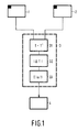
- Figure 1 shows a motion estimator
- Figure 2 shows an inter-intra-image decider.
- FIG. 3 shows a combination of a motion estimator and an inter-intra-image decider.
- Motion estimators and inter-intra-image deciders are part of a hybrid encoder (not shown) for the transmission of video images.
- the motion estimator determines a sub-block from sub-blocks of a previous video picture, which among the sub-blocks to be selected proves best as an estimate for the transmission of the current sub-block.
- the inter-intra-image decision maker decides whether the amount of data required to transmit the current sub-block using the selected sub-block serving as an estimate is less than the amount of data required to transmit the current sub-block as a whole.
- the motion estimator shown in FIG. 1 consists of a first and a second image memory 1, 2, a calculation module 3 and a minimum value register 4.
- the calculation module 3 is composed of a subtractor 31, an absolute value generator 32 and a summer 33.
- the current video image is stored in the first image memory 1 and the video image preceding the current video image is stored in the second image memory 2.
- the pixels of the video images are stored in a known manner in the form of the luminance and chrominance values representing them as binary values.
- a sub-block T of the current video image to be transmitted is fed to a first input of the calculation module 3 via a selection circuit (not shown).
- a sub-block T 'of the previous video image stored in the second image memory is selected in each case via a search area circuit, also not shown, and fed to a second input of the calculation module 3.
- the inputs of the calculation module are each connected to a first and second input of the subtractor 31.
- the subtractor 31 subtracts the values of the luminance or chrominance values corresponding to each other from the position of the respective sub-blocks.
- the difference values are fed to the absolute amount generator 32, in which all negative difference values are multiplied by the value -1. In this way, difference amounts are obtained from the difference values, which are fed to the input of the summer 33.
- the difference amounts of the individual pixels are added up in the summer 33. Before the start of the respective summation of the individual amounts, the content of the totalizer is deleted by a control pulse.
- the output values of the summer 33 are fed to the minimum value register 4.
- the content of the minimum value register is also set to the largest possible storable value.
- the respective value led to the minimum value register is compared with the value already stored in the minimum value register 4 by means of a logic circuit. If the new value is smaller than an already saved value, the new value is saved; if the new value is larger, the saved value is not changed.
- a control pulse is generated by the logic circuit which is fed to the search range circuit. With this control pulse, the addressing formed for the just selected sub-block of the previous video picture, which corresponds to the motion vector, is stored in a vector register, not shown.
- the sub-blocks removed from the second image memory 2 for selection are those which are most similar to the current sub-block in terms of the sum of the difference amounts.
- the optimal motion vector is thus in the vector register.
- the sum of the difference amounts, which is in the minimum value register is a measure of the length of the transmission code required for a transmission of the current sub-block with the aid of this selected sub-block serving as an estimate. The calculation of this value is also part of the inter-intra-image decision.
- Figure 2 shows an inter-intra-image decider, which is constructed with a second calculation module 3 '.
- the structure of the second calculation module 3 ' does not differ from the structure of the first calculation module 3, which is used in the motion estimator.
- the second calculation module therefore also consists of a subtractor 31 ', an absolute value generator 32' and a summer 33 '.
- the inter-intra-image decider consists of the image memory 1, the minimum value register 4, an average value register 5, a characteristic curve decider 6 and a register 7.
- a field T of the current video image is fed to the first input of the calculation module 3 'as in the motion estimator.
- the output of the calculation module 3 ' is connected to the mean value register 5.
- the minimum value register 4 is the minimum value register of the motion estimator already described.
- the outputs of the minimum value register 4 and the mean value register 5 are led to the inputs of a characteristic curve decision maker 6.
- the characteristic curve decider 6 is designed as a PROM in the exemplary embodiment.
- a single bit is output to a signal output S1. By means of this bit, the signal path switches of the hybrid encoder are appropriately switched over for intra-picture coding or inter-picture coding.
- Register 7 is connected to the second input of calculation module 3 in such a way that the value at the second input of subtractor 31 is divided by a sixty-fourth as compared to the value temporarily stored in register 7.
- Register 7 has a further input C1, via which the content of register 7 can be set to zero by a control signal S2. This control signal is generated by a control circuit, not shown.
- the average of the current sub-block is calculated and then the difference values between the current sub-block and a sub-block, the pixels of which all have the calculated average, are determined and added up.
- the calculation module 3 ' formed from the subtractor 31', the absolute value generator 32 'and the summer 33'.
- the mean value of the current sub-frame is determined in a first calculation step and the difference values between the current sub-frame and the mean value are formed in a second calculation step.
- This value is transferred to register 7, where it is divided by sixty-four.
- the number sixty-four corresponds to the number of pixels of a sub-block, so that the arithmetic mean of the pixels of a sub-block is formed in this way.
- the division by sixty-four is implemented in the exemplary embodiment by wiring the outputs of register 7, in which the eight lowest outputs of register 7 have been left open.
- the output of the ninth bit was at the input of the first bit of the subtractor 31 ', the output with the tenth bit at the input with the second bit of the subtractor 31 'and so on.
- the mean value of the current sub-block is present at the second input of the subtractor in the second calculation step.
- the subtractor 31 ' now calculates the differences between the current sub-block and the arithmetic mean of the current sub-block. From these values, the absolute values are again formed and summed up in the summer 33 '. The result of this calculation is stored in the mean value memory 5.
- the characteristic curve decision maker 6 decides in a known manner in which case the transmission of a motion vector or the transmission of the entire partial block is more advantageous.
- This calculation of the intra-image value in two passes makes it unnecessary to use an additional totalizer for calculating the mean value of a sub-block. This leads to not inconsiderable savings, since this summer should also be constructed as a parallel processing unit due to the high processing speed.
- FIG. 3 shows a particularly advantageous embodiment of the invention.
- FIG. 3 schematically shows the structure of a combination of a motion estimator and an inter-intra-image decider with only a single calculation module.
- the modules which have the same function as in FIGS. 1 and 2 are identified by the same reference numerals.
- the exemplary embodiment consists of a first and a second image memory 1, 2, a calculation module 3, a minimum value register 4, a mean value register 5, a characteristic curve decider 6, a register 7 and a multiplexer 8.
- the first input of the calculation module is connected via a control circuit (not shown) connected to the first image memory 1.
- the output of the calculation module 3 is led to the inputs of the minimum value memory 4 and the mean value register 5.
- the output values of the calculation module 3 are optionally stored in the minimum value register 4 or in the mean value register 5 by control commands from a control circuit (not shown).
- the output values of the minimum value register 4 and the mean value register 5 are fed to the inputs of the characteristic curve decision maker 6.
- the output of the calculation module 3 is also routed to the input of the register 7, the output of which is routed to a second input B of a multiplexer 8.
- a first input A of the multiplexer is connected to the second image memory 2 via a search area circuit, not shown.
- the output of the multiplexer is connected to the second input of the calculation module 3.
- a control pulse S3 of a control circuit, not shown, selectively connects input A or input B to the output of the multiplexer.
- the circuit arrangement shown works either as a motion estimator or as an inter-intra-image decider. If the input A of the multiplexer is connected to the output of the multiplexer 8 by the control pulse S2, this circuit corresponds completely to the motion estimator shown in FIG. If, on the other hand, the control signal S2 connects the input B of the multiplexer to the output of the multiplexer 8, the circuit shown in FIG. 3 corresponds completely to the inter-intra-image decider shown and explained in FIG.
- the illustrated exemplary embodiment work in quasi-time-division multiplex mode, optionally as a motion estimator or as an inter-intra-image decider, only a single calculation module 3 being required.
Landscapes
- Engineering & Computer Science (AREA)
- Multimedia (AREA)
- Signal Processing (AREA)
- Compression Or Coding Systems Of Tv Signals (AREA)
Claims (5)
- Codeur hybride pour images vidéo, dans lequel des pixels voisins d'une image vidéo sont regroupés en blocs partiels, comportant une première mémoire image (1) pour stocker les images actuelles et une seconde mémoire image (2) pour stocker les images précédant les images actuelles, un dispositif d'évaluation de mouvement et un dispositif de décision d'image inter/intra, caractérisé en ce que deux modules de calcul identiques (3, 3') sont prévus chacun avec une première et une seconde entrée et une sortie, le premier module de calcul (3) étant affecté au dispositif d'évaluation de mouvement et le second module de calcul (3') étant affecté au dispositif de décision d'image inter/intra, chaque module de calcul (3, 3') contenant un soustracteur (31), dont la sortie peut être acheminée à un totalisateur (32) via un formateur de valeurs absolues (32), étant entendu qu'il est prévu :- d'acheminer au premier module de calcul (3) à la première entrée, le bloc partiel actuel en question (T) et à la seconde entrée un bloc partiel (T) précédant le bloc partiel actuel (T'), et- d'acheminer au second module de calcul (3'), à la première entrée, le bloc partiel actuel en fonction (T) et, à la seconde entrée, la valeur moyenne du bloc partiel actuel.
- Codeur hybride pour images vidéo, dans lequel des pixels voisins d'une image vidéo sont regroupés en blocs partiels, comportant une première mémoire image (1) pour stocker les images actuelles et une seconde mémoire image (2) pour stocker les images précédant les images actuelles, un dispositif d'évaluation de mouvement et un dispositif de décision d'image inter/intra, caractérisé en ce qu'un module de calcul (3) est doté d'une première et d'une seconde entrée et d'une sortie, le module de calcul (3) contenant un soustracteur (31) dont la sortie peut être acheminée à un totalisateur (32) via un formateur de valeurs absolues (32), étant entendu qu'il est prévu d'acheminer au module de calcul (3), à la première entrée, le bloc partiel actuel en question (T) et, à la seconde entrée, au choix, un bloc partiel (T') précédant le bloc partiel actuel (T) ou la valeur moyenne du bloc partiel actuel.
- Codeur hybride selon la revendication 1 ou 2, caractérisé en ce que la valeur zéro peut être acheminée à la seconde entrée du module de calcul.
- Codeur hybride selon la revendication 1, 2 ou 3, caractérisé en ce qu'entre la seconde entrée et la sortie du module de calcul (3' ou 3) est installé un registre (7) dont la valeur de sortie peut être diminuée d'un facteur prédéfinissable par rapport à la valeur d'entrée du registre.
- Codeur hybride selon la revendication 4, caractérisé en ce que le facteur correspond au nombre de pixels d'un bloc partiel.
Applications Claiming Priority (2)
| Application Number | Priority Date | Filing Date | Title |
|---|---|---|---|
| DE3811535 | 1988-04-06 | ||
| DE3811535A DE3811535A1 (de) | 1988-04-06 | 1988-04-06 | Hybrid-codierer fuer videosignale |
Publications (3)
| Publication Number | Publication Date |
|---|---|
| EP0336509A2 EP0336509A2 (fr) | 1989-10-11 |
| EP0336509A3 EP0336509A3 (en) | 1990-03-07 |
| EP0336509B1 true EP0336509B1 (fr) | 1993-09-29 |
Family
ID=6351482
Family Applications (1)
| Application Number | Title | Priority Date | Filing Date |
|---|---|---|---|
| EP89200828A Expired - Lifetime EP0336509B1 (fr) | 1988-04-06 | 1989-03-31 | Codeur hybride pour signaux vidéos |
Country Status (4)
| Country | Link |
|---|---|
| US (1) | US4947248A (fr) |
| EP (1) | EP0336509B1 (fr) |
| JP (1) | JP2831372B2 (fr) |
| DE (2) | DE3811535A1 (fr) |
Families Citing this family (9)
| Publication number | Priority date | Publication date | Assignee | Title |
|---|---|---|---|---|
| US5047850A (en) * | 1989-03-03 | 1991-09-10 | Matsushita Electric Industrial Co., Ltd. | Detector for detecting vector indicating motion of image |
| FR2644914B1 (fr) * | 1989-03-24 | 1991-05-31 | Labo Electronique Physique | Dispositif d'estimation de mouvement dans des images de television |
| GB8909498D0 (en) * | 1989-04-26 | 1989-06-14 | British Telecomm | Motion estimator |
| JPH0385884A (ja) * | 1989-08-29 | 1991-04-11 | Sony Corp | 画像の動き検出回路 |
| US5644660A (en) * | 1992-04-09 | 1997-07-01 | Picturetel Corporation | Method and apparatus for efficiently transmitting forced updates in a moving picture codec |
| US5387938A (en) * | 1992-10-08 | 1995-02-07 | Matsushita Electric Industrial Co., Ltd. | Adaptive interframe/intraframe block coding method and apparatus |
| US5592226A (en) * | 1994-01-26 | 1997-01-07 | Btg Usa Inc. | Method and apparatus for video data compression using temporally adaptive motion interpolation |
| US5486863A (en) * | 1994-04-29 | 1996-01-23 | Motorola, Inc. | Method for determining whether to intra code a video block |
| US7949047B2 (en) * | 2003-03-17 | 2011-05-24 | Qualcomm Incorporated | System and method for partial intraframe encoding for wireless multimedia transmission |
Family Cites Families (6)
| Publication number | Priority date | Publication date | Assignee | Title |
|---|---|---|---|---|
| US4442454A (en) * | 1982-11-15 | 1984-04-10 | Eastman Kodak Company | Image processing method using a block overlap transformation procedure |
| JPS61114677A (ja) * | 1984-11-09 | 1986-06-02 | Nec Corp | 動画像信号の適応予測符号化復号化方式及びその装置 |
| EP0201679B1 (fr) * | 1985-04-17 | 1991-03-13 | Siemens Aktiengesellschaft | Procédé de réduction de données d'images pour des signaux de télévision numériques |
| DE3629472A1 (de) * | 1986-08-29 | 1988-03-03 | Licentia Gmbh | Verfahren zur bewegungskompensierten bild-zu-bild-praediktionscodierung |
| JPH082106B2 (ja) * | 1986-11-10 | 1996-01-10 | 国際電信電話株式会社 | 動画像信号のハイブリツド符号化方式 |
| SE457402B (sv) * | 1987-02-20 | 1988-12-19 | Harald Brusewitz | Foerfarande och anordning foer kodning och avkodning av bildinformation |
-
1988
- 1988-04-06 DE DE3811535A patent/DE3811535A1/de not_active Withdrawn
-
1989
- 1989-03-31 DE DE89200828T patent/DE58905725D1/de not_active Expired - Fee Related
- 1989-03-31 EP EP89200828A patent/EP0336509B1/fr not_active Expired - Lifetime
- 1989-04-04 JP JP1084157A patent/JP2831372B2/ja not_active Expired - Lifetime
- 1989-04-05 US US07/333,485 patent/US4947248A/en not_active Expired - Lifetime
Also Published As
| Publication number | Publication date |
|---|---|
| JP2831372B2 (ja) | 1998-12-02 |
| DE58905725D1 (de) | 1993-11-04 |
| US4947248A (en) | 1990-08-07 |
| JPH0229088A (ja) | 1990-01-31 |
| DE3811535A1 (de) | 1989-10-19 |
| EP0336509A2 (fr) | 1989-10-11 |
| EP0336509A3 (en) | 1990-03-07 |
Similar Documents
| Publication | Publication Date | Title |
|---|---|---|
| DE3874703T2 (de) | Kodier- und dekodierverfahren und vorrichtung fuer die bilduebertragung ueber ein netz mit einem variablen datenfluss. | |
| DE3751529T2 (de) | System zum Kodieren eines Bewegtbildsignals. | |
| DE69525009T2 (de) | Verfahren zur differentiellen Kodierung von Bewegungsvektoren mit Mittelwertprädiktion | |
| DE3882469T2 (de) | Videokoder. | |
| DE69330620T2 (de) | Verfahren und Einrichtung zur Bildkodierung | |
| DE69124536T2 (de) | Bildkodiervorrichtung | |
| DE69021500T2 (de) | Bedingungsgemässe bewegungskompensierte Interpolation von digitalen Bewegtbildsignalen. | |
| DE2740945C3 (de) | Verfahren zum Übertragen von Bildsignalen mit Hilfe der Differenz-Puls-Code-Modulation (DPCM) und geste uertem Quantisierer | |
| DE69637335T2 (de) | Bildsignalkodierungsmethode und -vorrichtung | |
| DE19531049C2 (de) | Verfahren zum Komprimieren von Daten und Codierungsvorrichtung | |
| DE69111264T2 (de) | Verbesserungen von Systemen zur Hybrid-Kodierung eines Videosignals. | |
| DE4339753A1 (de) | Vorrichtung zum Komprimieren und Dekomprimieren von Bilddaten | |
| DE19739266B4 (de) | Verfahren und Vorrichtung zum Kodieren binärer Formen | |
| DE19802860B4 (de) | Verfahren und Vorrichtung zum kontext-basierten arithmetischen Codieren/Decodieren | |
| DE3613343A1 (de) | Hybrid-codierer | |
| EP0336509B1 (fr) | Codeur hybride pour signaux vidéos | |
| DE69521873T2 (de) | Verfahren zum Auswählen von Bewegungsvektoren und Bildverarbeitungsvorrichtung zur Durchführung des Verfahrens | |
| DE69610595T2 (de) | Kontrollverfahren der Codemenge für kodierte Bilder | |
| DE69324661T2 (de) | Verfahren und Vorrichtung zur Bildcodierung und -decodierung | |
| DE69328346T2 (de) | Vorrichtung zur Kodierung von digitalen Fernbildsignalen | |
| DE3714589A1 (de) | Videosignal-codierer mit dpcm und adaptiver praediktion | |
| DE69512824T2 (de) | Kompressions- und Dekompressionsverfahren für mehrdimensionale mehrwertige Farbbilder | |
| EP0525900B1 (fr) | Circuit de filtrage pour le pré-traitement d'un signal vidéo | |
| DE4405803C2 (de) | Verfahren zur Quellcodierung | |
| EP1110407B1 (fr) | Procede et dispositif pour le codage et le decodage d'une image numerisee faisant appel a un vecteur de deplacement total |
Legal Events
| Date | Code | Title | Description |
|---|---|---|---|
| PUAI | Public reference made under article 153(3) epc to a published international application that has entered the european phase |
Free format text: ORIGINAL CODE: 0009012 |
|
| AK | Designated contracting states |
Kind code of ref document: A2 Designated state(s): DE FR GB SE |
|
| PUAL | Search report despatched |
Free format text: ORIGINAL CODE: 0009013 |
|
| AK | Designated contracting states |
Kind code of ref document: A3 Designated state(s): DE FR GB SE |
|
| 17P | Request for examination filed |
Effective date: 19900904 |
|
| 17Q | First examination report despatched |
Effective date: 19920610 |
|
| GRAA | (expected) grant |
Free format text: ORIGINAL CODE: 0009210 |
|
| AK | Designated contracting states |
Kind code of ref document: B1 Designated state(s): DE FR GB SE |
|
| PG25 | Lapsed in a contracting state [announced via postgrant information from national office to epo] |
Ref country code: SE Effective date: 19930929 |
|
| REF | Corresponds to: |
Ref document number: 58905725 Country of ref document: DE Date of ref document: 19931104 |
|
| GBT | Gb: translation of ep patent filed (gb section 77(6)(a)/1977) |
Effective date: 19931223 |
|
| ET | Fr: translation filed | ||
| PLBE | No opposition filed within time limit |
Free format text: ORIGINAL CODE: 0009261 |
|
| STAA | Information on the status of an ep patent application or granted ep patent |
Free format text: STATUS: NO OPPOSITION FILED WITHIN TIME LIMIT |
|
| 26N | No opposition filed | ||
| REG | Reference to a national code |
Ref country code: GB Ref legal event code: 732E |
|
| REG | Reference to a national code |
Ref country code: FR Ref legal event code: TP |
|
| PGFP | Annual fee paid to national office [announced via postgrant information from national office to epo] |
Ref country code: FR Payment date: 19981215 Year of fee payment: 11 |
|
| PGFP | Annual fee paid to national office [announced via postgrant information from national office to epo] |
Ref country code: GB Payment date: 19981231 Year of fee payment: 11 |
|
| PGFP | Annual fee paid to national office [announced via postgrant information from national office to epo] |
Ref country code: DE Payment date: 19990331 Year of fee payment: 11 |
|
| PG25 | Lapsed in a contracting state [announced via postgrant information from national office to epo] |
Ref country code: GB Free format text: LAPSE BECAUSE OF NON-PAYMENT OF DUE FEES Effective date: 20000331 |
|
| GBPC | Gb: european patent ceased through non-payment of renewal fee |
Effective date: 20000331 |
|
| PG25 | Lapsed in a contracting state [announced via postgrant information from national office to epo] |
Ref country code: FR Free format text: LAPSE BECAUSE OF NON-PAYMENT OF DUE FEES Effective date: 20001130 |
|
| REG | Reference to a national code |
Ref country code: FR Ref legal event code: ST |
|
| PG25 | Lapsed in a contracting state [announced via postgrant information from national office to epo] |
Ref country code: DE Free format text: LAPSE BECAUSE OF NON-PAYMENT OF DUE FEES Effective date: 20010103 |